(2) When a space of less than 300 mm is available below the unit between the unit and the ceiling. Create access door 1 diagonally under the electrical box and access door 3 under the unit as shown in Fig.4.
CENTER OF GRAVITY
Center of gravity Y
ELECTRICAL WIRING DIAGRAMS
Switch (for mode selection)SW3(I.B.) Switch (for model selection) Plug (emergency operation) Switch (for mode selection) Switch (10th digit address set) Switch (connection no. set) Switch (for static pressure selection) Switch (for model selection) Switch (for static pressure selection) Switch (for capacity code) Thermistor (pipe temp. detection/water out) Thermistor (pipe temp. detection/water in)SWB(A.B.) AC reactor (power factor improvement)L1. CN32 CN52CN51CN41 Transmission terminal TB15 TH21 Thermistor (intake air temp. detection) TH23TH22.
SOUND LEVELS
5-1. Sound levels
PEFY5-2. NC curves
FAN CHARACTERISTICS CURVES
OPTIONAL PARTS
7-1. Optional parts line up for the Indoor unit
PEFY-WP-VMS1-E
7-2. Control box replace kit
Ceiling concealed (Middle static pressure type)
PEFY-WP-VMA-E
SPECIFICATIONS
Drive mechanism Directly driven by motor Directly driven by motor Directly driven by motor Directly driven by motor Refer to "Fan Characteristics Curves", according to the external static pressure, in DATABOOK for the usable range of air flow rate.
EXTERNAL DIMENSIONS
PEFY-WP20, 25, 32, 40, 50VMA-E
Switch (10th digit address set) Switch (for selecting static pressure) Switch (for selecting static pressure) Switch (BRANCH No.) Switch (for selecting mode). ZNR01,02 TH21 LED1 Thermistor (intake air temp. detection) LED(Power supply) LED(Remote control supply)TH23TH22 LED2 NAME SYMBOL SYMBOL I.B.
5-2. NC curves
PEFY-WP40,50VMA-E External Static Pressure: 35Pa
PEFY-WP40,50VMA-E External Static Pressure: 50Pa
PEFY-WP40,50VMA-E External Static Pressure: 70Pa
PEFY-WP40,50VMA-E External Static Pressure: 100Pa
PEFY-WP40,50VMA-E External Static Pressure: 150Pa
PEFY-WP40, 50VMA-E External Static Pressure: 35Pa
PEFY-WP40, 50VMA-E External Static Pressure: 50Pa
PEFY-WP40, 50VMA-E External Static Pressure: 70Pa
PEFY-WP40, 50VMA-E External Static Pressure: 100Pa
PEFY-WP40, 50VMA-E External Static Pressure: 150Pa
7-2. Filter box
1 - 36INDOOR UNITS
Floor standing (Concealed type)
PFFY-WP-VLRMM-E
Remarks Details on foundation work, duct work, insulation work, wiring, power source switch and other items will be referred to the installation manual. 6. Install a strainer (40 mesh or larger) in the pipe near the valve to remove foreign matter.
PFFY-WP20, 25, 32, 40, 50VLRMM-E
SW5SWA Fan Motor NOTE: The symbols used in the above wiring diagram are (HEA VY DOTTED LINE): FIELD WIRING (THIN POINTED LINE): OPTIONAL PARTS: CONNECTOR OR: CONNECTOR Thermistor (pipe temperature sense/water inlet) Thermistor (pipes) temp. detection/water out) Switch (for mode selection) At the receiving power source of transmission MA → Illumination switch (for performance code) Switch (10th place address set) Switch (for static pressure selection) Switch (for static pressure selection) Switch ( connection no. setting) Switch (for mode selection) Switch (for model selection) Connection (emergency operation) Switch (10th place address set) Switch (for static pressure selection) Switch (for static pressure selection) Switch (set no. connections) Switch (for mode selection) Switch (for model selection) Connector (emergency operation) Switch (for mode selection) Switch (for model selection) T portable terminal block.
1 - 48INDOOR UNITS
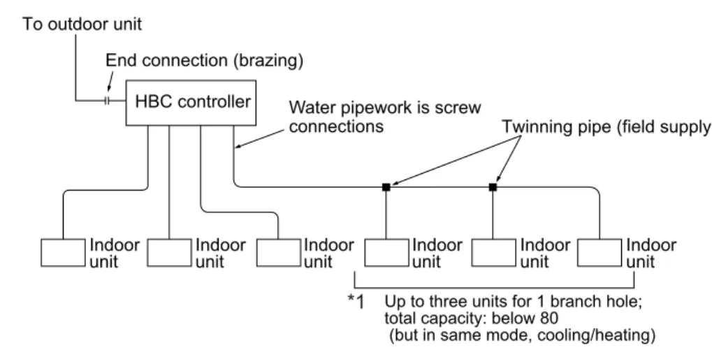
HBC controller
CMB-WP-V-G
For use in quiet environments with little background noise, place the HBC CONTROLLER at least 5 m away from indoor units. If leakage from below the HBC would not cause a problem in the installed location, installation of the sub drain pan is not necessary.
CMB-WP108V-G
Water pipe (EXP.Tank) Connecting pipe of outdoor unit (High pressure) Connecting pipe of outdoor unit (Low pressure) Sub drain pan. ø31 Detail of X section Detail of Y section. 2. Take note of service space as follows. Please note not to occupy service space by passing channels and pipes.)
Measured point)
OPTIONAL PARTS
6-1. Optional parts line up for the HBC controller
6-2. Sub drainpan
1 - 58INDOOR UNITS
CAPACITY TABLES
Capacity Table
Cooling [Ceiling concealed (Slim type)]
Cooling [Ceiling concealed (Middle static pressure type)]
Cooling [Floor standing (Concealed type)]
Heating [All indoor units]
HYBRID CITY MULTI 2. OUTDOOR UNITS
2 - 2OUTDOOR UNITS
HYBRID CITY MULTI
OUTDOOR UNITS
For details on foundation work, duct work, insulation work, electrical wiring, power source switch and other items, please refer to the installation manual. 3. When brazing pipes, wrap the refrigerant service valve with a wet cloth and keep the temperature of the refrigerant service valve below 120°C.
PURY-WP200,250YJM-A
With a space of at least 100 mm from the wall at the back of the appliance. With a minimum clearance of 300mm to the wall at the rear of the unit
PURY-WP200, 250YJM-A
CAPACITY TABLES
6-1. Correction by temperature
Correction by temperature (COP Priority Mode)
6-2. Correction by total indoor
6-3. Correction by piping length
Equivalent length = (Actual pipeline length at the farthest internal unit number of bends in the pipeline) [m]. Equivalent length = (Actual pipeline length at the farthest internal unit number of bends in the pipeline) [m].
Water pipe
PURY-WP200, 250YJM-A
Water piping design
6-4. Correction at frost and defrost
6-5. Correction by brine concentration
6-6. Operation temperature range
Combination of cooling/heating operation (Cooling main or Heating main)
2 - 18OUTDOOR UNITS
HYBRID CITY MULTI 3. CONTROLLER
MITSUBISHI ELECTRIC's Air-conditioner Network System. (MELANS)
System Controller
MELANS
OUTDOOR UNIT
HYBRID
INDOOR UNIT PEFY
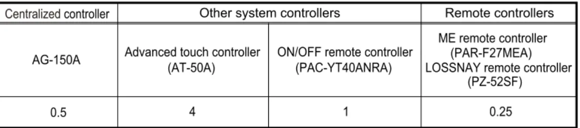
1-1. Function table of controllers
- Local remote controller
- Operation/DisplayFunctions
- Schedule and timer setting
- Restriction settings
- Miscellaneous items
- System remote controller
ON/OFF/Temperature setting can be performed up to 8 times one day of the week. The ON/OFF remote control can be connected to the indoor/outdoor transmission line without the power supply unit.
ON/OFF remote
LOSSNAYLOSSNAY
LOSSNAY MA remote
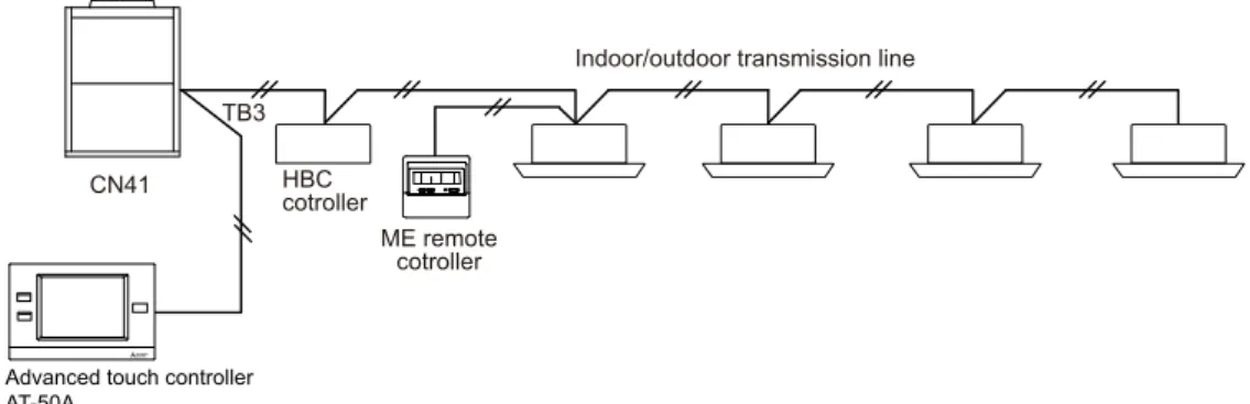
Power supply to AT-50A
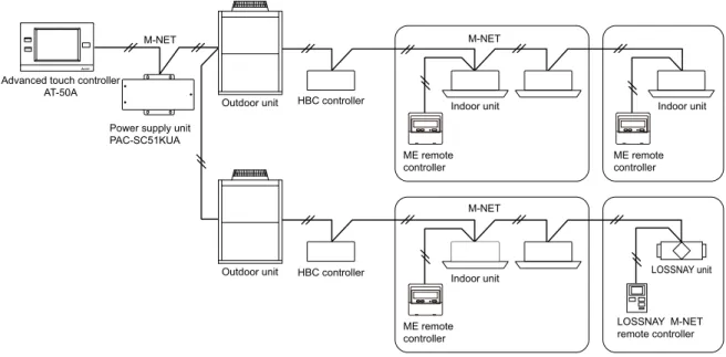
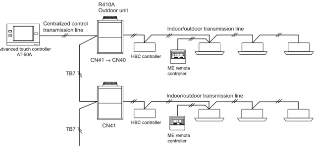
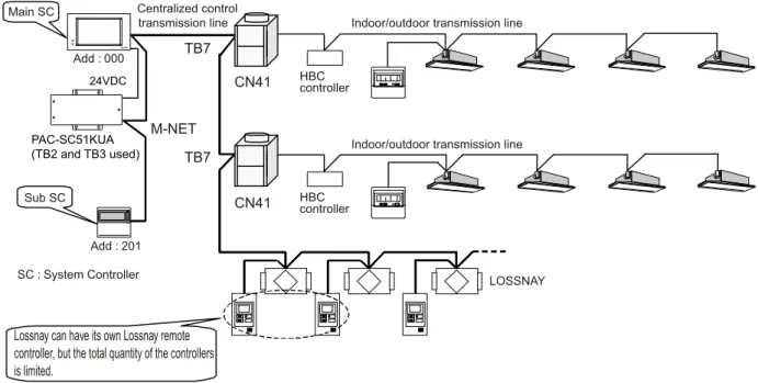
Power supply unit PAC-SC51KUA is recommended for AT-50A. See the schedule below; For more information, refer to the installation manual of the power supply unit PAC-SC51KUA. Power supply from M-NET via connector TB7 of the outdoor unit. 2, AT-50A receives power supply from M-NET from R410A outdoor unit connector TB7.
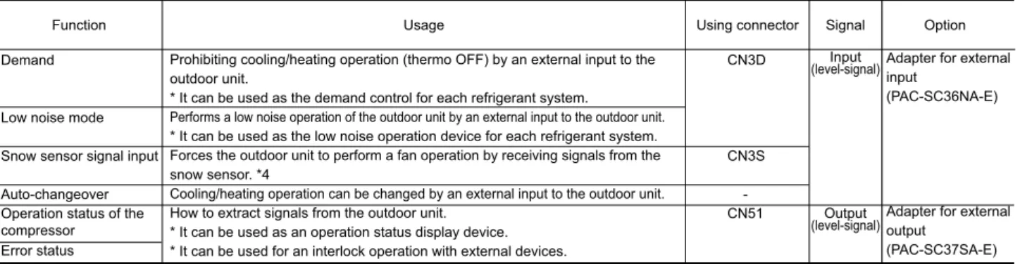
1). External signal input function
- to 1 sec Signal 2 (stop)
- External input/output usage
Lead wire Details of each terminal
- Screens of AT-50A
- Together with integrated centralized control software TG-2000A, and/or PI, DIDO controller, many optional
- One AG-150A can control maximum 50 units (including LOSSNAY). Up to 150 units (including LOSSNAY) can
- Power supply to AG-150A
Up to 150 units (including LOSSNAY) can be controlled by one AG-150A connected to three expansion controllers. AG-150A connected to PAC-YG50ECA cannot be connected to PLC (PAC-YG21CDA).
NOTE: For information about AG-150A connected with the expansion controller, refer to the following section(s)
ON/OFF (Level signal)
ON/OFF prohibit/permit
NOTE : When using the AG-150A connected with the expansion controller, use external input/output function of the expansion controller
Contact relay, DC power supply, extension cord, etc. must be prepared separately on site. Relays, lamps, diodes and extension cords etc. must be prepared separately on site.
NOTE
LAN connection function
Make the LAN connection before installation and connect the cable to the body in the same method as the M-NET transmission line installation. Use a security device such as a VPN router when connecting the AG-150A to the Internet to prevent unauthorized access.
Use a security device such as a VPN router when connecting the AG-150A to the Internet to prevent unauthorized access
When a LAN is already connected, decide the IP address through consultation with the system administrator and connect to the LAN body after changing the IP address.
If no security devices are installed, the operation settings may be changed by an unauthorized person without the knowledge of the user.)
- Browser screens of AG-150A
- Liquid crystal displays of AG-150A
- One GB-50ADA can control maximum 50 Indoor units(including LOSSNAY). The integrated
- Taking advantage of GB-50ADA's Web functions, alarming E-mail containing address and error code
- Together with integrated centralized control software TG-2000A, and/or other controller (DIDO, AI,
- The interlock-control option enables interlocked operations of air conditioning unit groups and the general equipment groups,
- connectable
- NETHUB
- NET remote controller ON/OFF remote
- Run)
- Stop)
- External input/output usage
During an emergency stop, the Run/Stop mode cannot be changed from the local remote control, and the Run/Stop and Prohibit/Permit settings cannot be changed from the GB-50ADA. The Run/Stop mode cannot be changed from the local remote control, and the Run/Stop modes and Prohibit/Allow settings cannot be changed with the GB-50ADA.
2). External signal output function
If pulse signals to operate the units are received while the units are running, the units will continue their operation (same as Stop, Stop and Enable signals). Use a security device such as a VPN router when connecting the GB-50ADA to the Internet to prevent unauthorized access.
Use a security device such as a VPN router when connecting the GB-50ADA to the Internet to prevent unauthorized access
If no security devices are installed, the operation settings may be changed by an unauthorized person without the knowledge of the user.)
LAN connection function
Browser screens of GB-50ADA
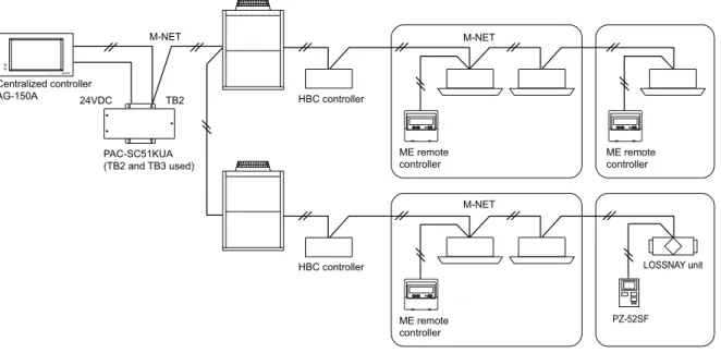
PAC-SC51KUA supplies M-NET DC power (22-30V) and 24V to TB2 and TB3 respectively; the first is for centralized broadcast use and the second is for AG-150A operation and LAN function. When using the PAC-SC51KUA as the power supply for the system controller, the capacity for the system controller is considered as follows.
TB7M-NET
PAR-F27MEA) LOSSNAY remote controller
PZ-52SF)Centralized controller*1
It is possible for the AG-150A to receive power from one of the Outdoor Units, but there is a risk that a power failure from the Outdoor Unit will cause the AG-150A to malfunction on the entire system. -YG50ECA has a built-in function to supply power to the M-NET transmission line. power supply coefficient: 6).
24VDC
It is recommended that the number of devices you want to connect between the AG-150A and the PAC-YG50ECA does not exceed four.
24VDCLAN
NET NET
NETNET
LAN M-NET
Example of Basic System Configuration
The TG-2000A can realize the following functions by using the AG-150A or GB-50ADA option (license). Depending on the versions of TG-2000A and AG-150A/GB-50ADA, some of the functions may not be available for use.
GB-50ADA can be
When the AG-150A is connected to the PAC-YG50ECA, units are counted based on the number of PAC-YG50ECA connected. The data for each AG-150A/GB-50ADA can be grouped and used to control the operation of up to 2000 units in floor or block units etc. from the PC screen.
List of integral software functions
List of TG-2000A functions
Using a PI controller/PLC or a watt-hour meter, the power rate can be allocated, energy saving control can be performed, and other common equipment can be controlled.
Requirements (system recommendations)
PC CPU
NET LAN
NET *1
Up to 150 units/groups (including LOSSNAY) can be controlled from one BAC-HD150 with three expansion controllers PAC-YG50ECA. When using the dual setpoint function, no expansion controllers can be connected and only a maximum of 50 units/groups can be controlled from each BAC-HD150.
22-30 VDC Interface to M-NET transmission lines
HYBRID CITY MULTI can be easily combined into a Building Management System (BMS) via BACnet® and the M-NET adapter BAC-HD150.
NETCentral
LAN1
NETME remote
AG-150A LAN1
LANLAN2
MITSUBISHI ELECTRIC's HYBRID CITY MULTI has its intelligent way of performing peak cutting control while maximizing the air conditioning effect.
AG-150A/GB-50ADA
The TG-2000A or Initial Setting Web sets the following energy saving items and energy saving. AG-150A/GB-50ADA performs energy-saving operation to the indoor units with the set detail.
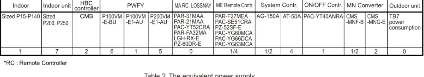
Taking as 1 the power consumption of the P15-P140 size indoor unit, the equivalent power consumption or supply of others are listed in Table 1 and Table 2. 25 PAC-SF46EPA transmission amplifier. With the equivalent power consumption values in Table 1 and Table 2, the PAC-SF46EPA can be designed in the air conditioner system to ensure proper system communication according to A, B, C. A) First, count from TB3 to TB3 side the total quantity of Indoor units, ME remote controls and system controllers.
External Dimensions
By combining the use of the AG-150A/GB-50ADA and TG-2000A, the charges for each unit can be calculated and the peak cutting (eg demand control) can be carried out.
CAUTION
TB3 M-NET
TB7 Centralized control line
GB-50ADA)
AG-150A(GB-50ADA) web or TG-2000A
UPS)
UPS)24 VDC
HYBRID CITY MULTIHBC controller
Specifications
However, when electric power is supplied to the M-NET centralized control line from the R410A series outdoor unit*1 without using a power supply unit for the transmission line, use single-point grounding at the TB7 of that outdoor unit. It is recommended to connect an uninterruptible power supply (UPS) to the 24 VDC power source to prevent the loss of pulse data in the event of a power failure.
NET transmission line
VDC power source
Tightening torque for terminal screws: 1 N·m Connect this unit's M-NET transmission line to a transmission line power supply unit (PAC-SC51KUA) or an outdoor unit (either a centralized control line or indoor control line can be connected). Only the M-NET circuit of this device receives power from the M-NET transmission line. corresponding to one ME remote control).
FGNoise
Place the power line and M-NET transmission line on the outside to ensure that the terminal block is not affected by any external force. Cover the shielded line of the M-NET transmission line with materials such as vinyl tape and prevent shorting with the plates.
24 VDC Power
Pulse input (non-voltage a-contact)
The pulse unit (weight) can be added to each of the channel 1 through 4 inputs. The pulse unit of the watt-hour meter used must be 1 kWh/pulse or less.
System Operation Test
The polarity of the input terminals is important, so be sure to match the polarity when using contacts that have polarity. It is recommended to provide an external switch for general purpose equipment in case of failure of the DIDO controller or a peripheral part.
Specifications (1). Device Specifications
ON/OFF, (ON)
OFF) (*4)
ON/OFF, (ON)
One contact connected to this device is calculated as the equivalent of one indoor unit connected to AG-150A/GB-50ADA. If the M-NET transmission line of this unit is connected to the M-NET indoor control line and the outdoor unit has failed due to, for example, power cut for maintenance or malfunction, the DIDO controller cannot be controlled from the system controller.
24 VDC Power supply
However, the number of units that can be connected to an AG-150A/GB-50ADA is up to 50, including the number of contacts used on this device, an indoor unit, LOSSNAY unit, etc. For the shield ground of the M-NET centralized control line, use single-point grounding at the power unit for the transmission line.
HYBRID CITY MULTI HBC controller
Furthermore, when connecting this device to the M-NET indoor control line, use grounding at the TB3 for each outdoor unit system. Control of the ON/OFF remote control is only possible with channel 1 of a standard terminal block.
AG-150A (GB-50ADA)
Power supply unit PAC-SC51KUA Power supply for M-NET transmission line This is not necessary if the power supply is to be supplied from an external unit. Connect a circuit containing the following components to the supply primary side of the 24 VDC power supply.
Field Connections
Standard Terminals (Channels 1 and 2) (1- Input
Make sure that the copper wires do not short circuit the plates (cap, small cap) or neighboring wires. If strained, use a wire guide or junction terminal to relieve stress on the terminal block.
MAX: 24 VDC, 5 W MIN: 5 VDC, 2 mW
Interlock control
The DIDO controller (PAC-YG66DCA) has an interlock control function which enables the operation or setting of temperature changes on the M-NET devices such as indoor units and also enables signal output to the contacts of the DIDO controller. 5. The system must be configured in a way that integrates the operation of the interlocked fire and emergency control systems.
GB-50ADA
Before using the lock command, you must agree to the following. 1. This feature should not be used for disaster prevention or security purposes. It is not designed for use in life-threatening situations). 2.Features must not be added that allow the unit to malfunction by defeating safety features, such as an external ON/OFF switch or a short circuit.
HBC controller
3. Those settings for the function that are not supported by the connected units should not be made.
ON/OFF
In addition, when connecting the M-NET transmission line of this equipment to the M-NET indoor control line, use grounding at TB3 for each outdoor unit system. The sensor connected to the AI controller can only be monitored by the AG-150A/GB-50ADA.
HYBRID CITY MULTIHBC
If the M-NET transmission line of this device is connected to an M-NET indoor control line and the outdoor unit is off because, for example, the power supply is interrupted for service or there is a fault, the AI controller cannot be set not and monitored from the system controller. If the M-NET transmission line of this device is connected to an M-NET indoor control line and the outdoor unit is off because, for example, the power supply is interrupted for service or there is a fault, the AI controller cannot be set not and monitored from the system controller.
FGM-NET
It is important to note the polarity when connecting to the 24 VDC power terminal block. Failure to properly connect and secure the wires may cause heat generation and fire.
A/B/S Tightening torque for terminal screws: 1 N·m
Channel 1 Pt100 Input
If it is stressed, use a wire guide or jumper terminal to relieve the stress on the terminal block. type for which power is supplied to the signal line) is connected. AI controller (PAC-YG63MCA) has a latch control function, which enables operation or set temperature change on the M-NET devices such as indoor units.
System component
4-1. HYBRID CITY MULTI
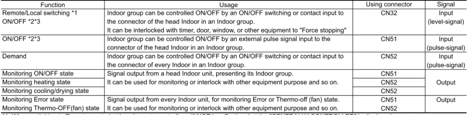
The indoor group can be controlled ON/OFF by an ON/OFF switch or contact input on the Indoor header connector on an Indoor group. The indoor group can be controlled ON/OFF by an external pulse signal input to the Indoor header connector on an Indoor group.
Caution
Contact rated voltage >= 15VDC Contact rated current >= 0.1A Minimum applicable load =< 1mA at DC. Contact rated voltage >= 15VDC Contact rated current >= 0.1A Minimum applicable load =< 1mA at DC.
HYBRID CITY MULTI 4. SYSTEM DESIGN
4 - 2SYSTEM DESIGN
HYBRID CITY MULTI SYSTEM DESIGN
Electrical work
1-1. General cautions
1-2. Power supply for Indoor unit and Outdoor unit
PURY-WP-YJM
RLA(A)
1-3. Power cable specifications
1-4. Power supply examples
1-4-1.PURY-WP200-250YJM-A
M-NET control
2-1. Transmission cable length limitation
2-2. Transmission cable specifications
2-3. System configuration restrictions
- Maximum 2 remote controllers for 1 Group;
- Maximum 3 System controllers are connectable when connecting to TB3 of the outdoor unit
- Maximum 6 System controllers are connectable when connecting to TB7 of the outdoor unit, if the transmission power is supplied by the outdoor unit
- Connecting to TB3 of the outdoor unit and receiving power from the outdoor unit
- Connecting to TB7 of the outdoor unit and receiving power from the outdoor unit
Connects to TB7 of the outdoor unit but is powered by power supply unit PAC-SC51KUA. The power supply unit PAC-SC51KUA is not necessary if you only connect the LM-AP.
2-4. Address setting
ONSW contents Main
PAR-21MAA
ME, LOSSNAY Remote controller
- Outdoor units OC and OS in one refrigerant circuit system are automatically detected
- No address setting is needed
- Indoor units should be set with a branch number
- When a PAR-31MAA is connected to a group, no other MA remote controllers can be connected to the same group
/CN41: Change jumper from CN41 to CN 40 on outdoor control board will enable central transmission power supply to TB7;. Changing the jumper from CN41 to CN 40 at the LM-AP will enable the transmission power supply to the LM-AP itself.
PURY
Change the jumper on only one outdoor unit when the transmitting power is activated without using a power supply.). A power supply unit is recommended for use in a system with more than 1 outdoor unit, as the central transmitting power comes from TB7 of one of the outdoor units, so there is a risk that a failure of the outdoor unit will fail the entire system controller system.
Factory setting
Original contact setting of Outdoor, Indoor, Controllers, LM-AP and BM ADAPTER at shipment is as follows. When a PAR-31MAA is connected to a group, no other MA remotes can be connected to the same group.
Setting at the site
- Address should be set to Indoor units and centralized controller
- Address should be set to indoor units, LOSSNAY and system controller
- Address should be set to indoor units, system controller and ME remote controllers
- Address should be set to indoor units, LOSSNAY centralized controller, ME remote controllers
Channel 1, 2 and 3 are selectable for the wireless remote control and signal receiving unit (SRU) and must be set to the same channel. lt;Two outdoor units>
ME R/C ME R/CIndoor unit
M-NET power is supplied by the outdoor unit at TB3, while indoor unit and ME RC consume the M-NET power for transmission
Indoor units should be set with a branch number
Consider the power requirements for the number of connected devices for long M-NET cables. Only a single outdoor unit can be connected to a HYBRID CITY MULTI system.). It is necessary to change the connector of CN40 on the outdoor unit control board (only one outdoor unit) when the group is set between other refrigerant systems.
Group 4
It is necessary to set the remote control manually when setting groups on the different refrigerant systems.
ME R/CME R/C
ME R/CHBC controller
LAN GB-50ADAAG-150A
3 When a PAR-31MAA is connected to a group, no other MA remotes can be connected to the same group. 2 When a PAR-31MAA is connected to a group, no other MA remotes can be connected to the same group.
BM ADAPTER(01) HUB
BM ADAPTER(02)
Group 32
It is not necessary to connect the M-NET transmission line to the TB3 on BM ADAPTER. 5 Consult your dealer for restrictions on connecting both the AG-150A and the BM ADAPTER to the PAC-YG50ECA.
BACnet ®
When the dual setpoint function is used, no expansion controllers can be connected and only up to 50 units can be controlled from each BAC-HD150. 6 When the PAR-31MAA is connected to a group, other MA remotes cannot be connected to the same group.
LAN LAN2
BM ADAPTER CN41
Piping Design
3-1. R410A Piping material
Type-O : Soft copper pipe (annealed copper pipe), can be easily bent with human's hand
Type-1/2H pipe : Hard copper pipe (Straight pipe), is stronger than Type-O pipe of the same radial thickness
3-2. Piping Design
Piping length limitation
Drain piping work
Make sure the drain pipe is inclined downwards (slope more than 1/100) towards the discharge side. Do not use any glue for this as the drain pipe will need to be removed for servicing later.).
Discharge test
Ensure that any horizontal section of drainage pipe that is longer than 20m is supported with metal brackets to prevent it from bending, warping or vibrating.
Insulating drain pipes
VP-25Drain discharge port
3-2-3-1 Important notes on water pipework installation
Wrap the joint with sealing tape following the direction of the threads (clockwise), do not wrap the tape over the edge
Do not wrap the 1.5th through 2nd farthest threads away from the pipe end
The HBC system must be serviced at least once a year