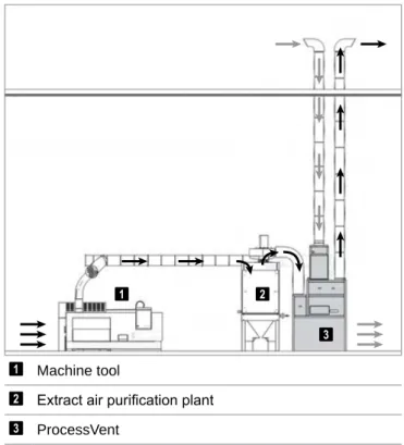
The fresh air volume is constant; it depends on the exhaust air volume. The exhaust air from the exhaust air cleaning system flows through the plate heat exchanger into the open air.
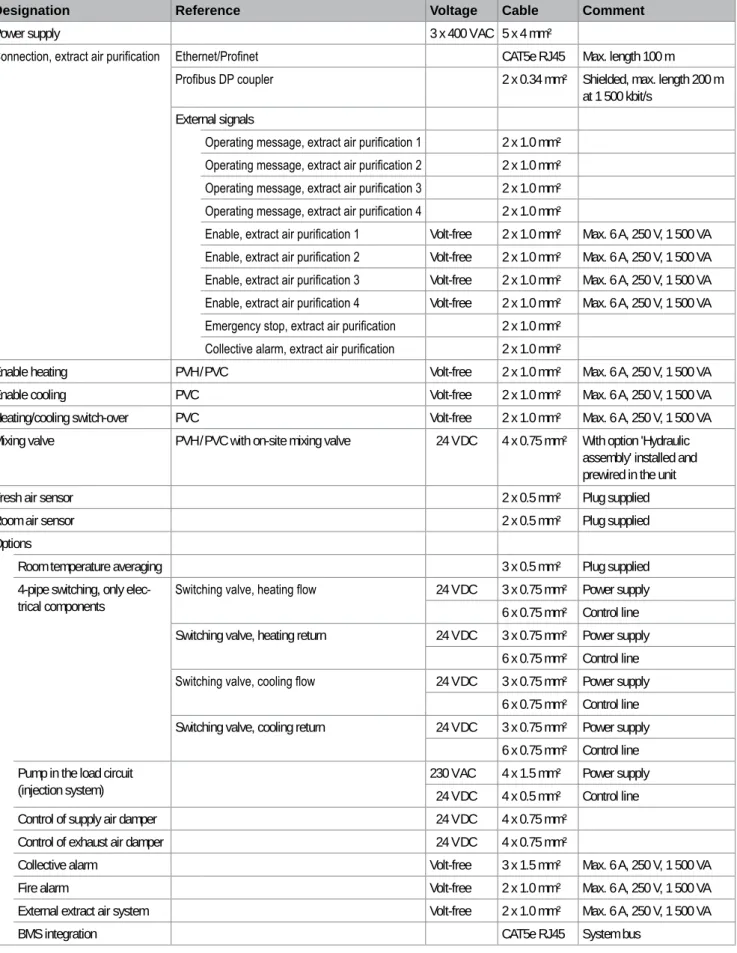
F4.2 Air flow rate, electrical connections
Sound level
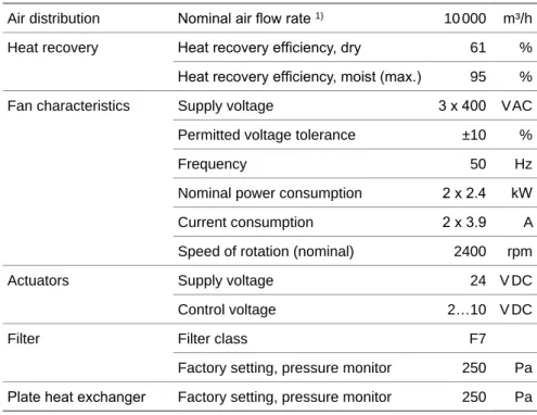
Technical data
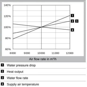
Heat output
Q = Battery heating output tS = Supply air temperature ΔpW = Water pressure drop mW = Water flow rate Table A5: Heat output from ProcessVent heat at -15 °C. Q = Battery heating output tS = Supply air temperature ΔpW = Water pressure drop mW = Water flow rate Table A6: Heat output from ProcessVent heat at -5 °C.
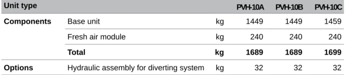
F4.5 Dimensions and weights
The fresh air module is intended for horizontal mounting on the base cabinet and equipped with plug connections for easy electrical installation; including connecting channel and cross support made of sheet steel, welded, with high-quality anti-corrosion primer and paint finish. The side walls made of sheet steel with a high-quality anti-corrosion primer and lacquer finish are screwed flush with these corners and sealed water- and oil-tight.
Specification texts
The casing of the fresh air module is painted in the RAL color of the customer's choice. Control of an on-site exhaust air damper depending on the operating condition of the exhaust air treatment plant; consisting of:■ Digital output routed to terminals in the control box.
ProcessVent cool PVC
Contents
Intended use
The exhaust air from the exhaust air cleaning system flows through an oil-tight plate heat exchanger and is led outwards via a channel; the heat it contains is transferred to the supply air.
User group
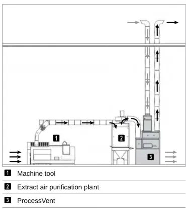
F2.1 Construction
Construction and operation
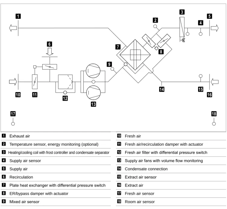
Operational diagram
Fresh air/recirculation damper with actuator Fresh air filter with differential pressure switch Supply fans with volume flow monitoring Condensate connection.
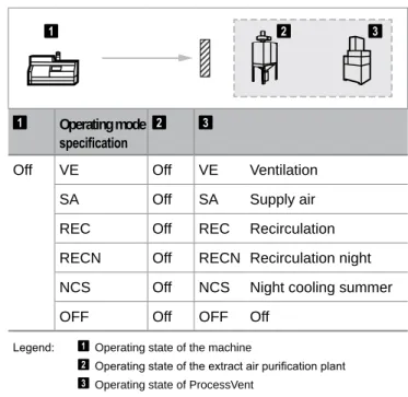
F2.3 Operating modes
Application limits
The unit is corrosion protected, but only suitable for use in applications where the exhaust air contains to a limited extent very aggressive substances (sulfur, methanol, acetone, toluene, etc.).
Unit type reference
Minimum airflow rate operation is recommended only in part-load or intermittent operation. This requires air to be blown into the room via a supply air duct and induction plugs. The total output of the unit is calculated from the heat output of the coil plus the output from energy recovery (Q + QER).
Q = Heat output from the coil tS = Supply air temperature ΔpW = Water pressure drop mW = Water flow rate Table B6: Heat output from the ProcessVent cools at -5 °C.
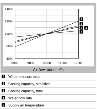
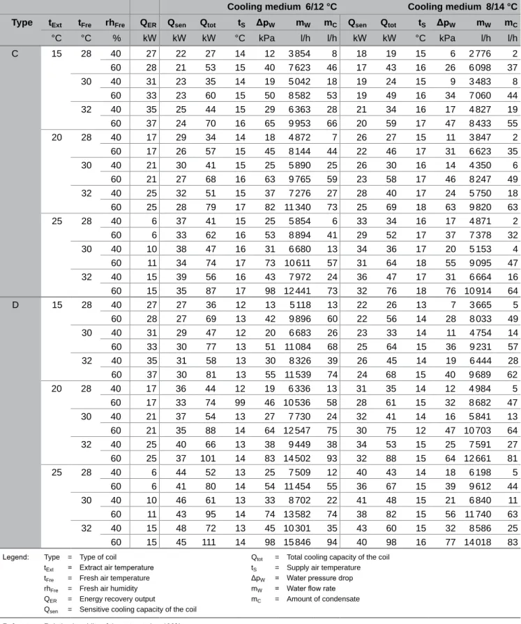
F4.5 Cooling capacity
Cooling medium 6/12 °C Cooling medium 8/14 °C Type tExt tFre rhFre QER Qsen Qtot tS ΔpW mW mC Qsen Qtot tS ΔpW mW mC. Qtot = Total coil cooling capacity tS = Supply air temperature ΔpW = Water pressure drop mW = Water flow rate mC = Condensate volume.
F4.6 Dimensions and weights
Opposite dampers for switching between fresh air operation and recirculation, including continuous operation with safety function in case of power failure. The circuit is installed in the supply air flow and sealed so that it is air and oil tight towards the exhaust air side; leak test as per company standard. The line balancing valve in flow matches the total resistance of the load to the distribution circuit.
Calculation of saved energy with a cross-flow plate heat exchanger and display on the user terminal; additional temperature sensor and analog input installed in the unit; fully prewired. Control and protection components of the heating/cooling pump integrated in the control box; digital output routed to the terminals in the control box.

ProcessVent PV
Energy recovery
Explanation: tExt = Extract air temperature rhExt = Extract air humidity QER = Energy recovery effect tS = Supply air temperature. Water- and oil-tight welded construction of steel for the transport of air-containing oil, insulated with closed-cell polycell (building material class B2 according to DIN 4102-1), equipped with media-resistant compensators (2 pcs.) with DIN flange connection pieces for connection to the site's exhaust air and return air duct. Defrosting if the plate heat exchanger is iced using the exhaust air flow during plant operation.
Electrical components and software interface to connect one or more (maximum 4) non-Hoval exhaust air cleaners to the Hoval ProcessNet control system; visualization via building management system or touch panel on the unit. Power supply for Hoval ProcessVent if it is installed in conjunction with non-Hoval exhaust air cleaning systems.
Options D
Supply air duct connection, left (K2)
The compensator for the supply air duct is mounted on the left side of the unit.
High-pressure fans (HV)
F3.2 Displacement flow diffuser (QL)
Fresh air module, horizontal (AH)
Paint finish as desired (AL)
The electrical components for the automatic changeover are installed in the terminal box and pre-wired. The electrical components for the automatic changeover are installed in the terminal box (4-pipe switching group and wiring on site; see electrical diagram for connections).
4-pipe switching
Return pump station water (RW)
Water from the return pumping station is used to remove condensate in applications where connection to the waste water system via a simple condensate line is not possible. Water-emulsion mixtures from a plate heat exchanger (with a preliminary emulsion separator, wet separator or dry filter).
Return pump station oil (RO)
Return pump station
Transport and installation E
Installation site
If the unit is equipped with a displacement diffuser, ensure smooth dispersion of the supply air flow (approx. 1 m free space all around, up to 1.8 m height). The unit must be accessible and the connecting lines must be able to be disassembled for maintenance and service work.
Assembly
F1.2 Connecting the air ducts
Heating/cooling coil
Depending on local conditions, check whether supply and return lines require linear expansion compensators and/or units require articulated connections. Refrigerant must not circulate in the heating/cooling coil when the unit is switched off.
Condensate connection
Hydraulic installation
The room air sensor and the fresh air sensor are supplied separately in the control box. Install the temperature sensors in a suitable location and wire them to the plug-in connectors on the unit. Connect the unit's frame to the foundation earth electrode and label it with an earth tag.
Electrical installation
Operating message return air cleaning 1 2 x 1.0 mm² Operating message return air cleaning 2 2 x 1.0 mm² Operating message return air cleaning 3 2 x 1.0 mm² Operating message return air cleaning 4 2 x 1.0 mm². Mixing valve PVH/PVC with on-site mixing valve 24 V DC 4 x 0.75 mm² With 'Hydraulic mounting' option installed and pre-wired in the unit.
Control systems F
ProcessNet system set-up
F1.1 Basic principles
- Operation
- Control mode
- Room temperature control in extract air operation
- Room temperature control in recirculation operation
- Control of the supply air volume flow
- Soft starting
- Defrost switch
- Frost protection switch
- Fan overrun
Depending on the actual value of the room temperature and the current deviation of the PI regulation, the regulator determines the set value of the supply air temperature. The supply air temperature is regulated to this set value; room temperature is not taken into account here. The volume flow of supply air is regulated depending on the actual value of the room temperature and the current regulation deviation.
Only after the supply air temperature has reached the set value, the fresh air damper opens fully. If the supply air temperature drops below a set value (6 K above the set frost protection temperature), the heating mixing valve opens continuously.
Control functions
- Connection, extract air purification
- Room temperature averaging (MR)
- Energy monitoring (EM)
- Design for injection system (ES)
- Control of supply air damper (ZK)
- Control of exhaust air damper (FK)
The room temperature can be controlled in 2 different ways in exhaust air operation – that is, in the operating modes VE (ventilation) and SA (supply air). One or more (max. 4) non-Hoval extraction systems are connected to the system via external signals. The amount of fresh air in the ProcessVent unit depends on the exhaust air volume flow of the individual systems.
This control is performed depending on an adjustable threshold value for the supply air volume flow. This check is performed depending on the operating condition of the extracted air cleaning plants.
Control options
4 room air sensors for averaging in the occupied area are supplied (wiring supplied on site). Energy monitoring determines the amount of recovered energy in the plate heat exchanger (separate counters for heating and cooling energy) and displays it on the operating terminal. For this reason, an additional temperature sensor is installed and pre-wired in the unit.
Instead of a diversion system, an injection system can also be installed in the load circuit. In the design for the injection system, additional components for controlling the pumps in the load circuit are installed in the control box.
F4.7 Touchpanel on the unit (TP)
Power supply (LV)
Alarms and monitoring
6 BMS parameter list AddressOffsetSymbolnameTypeDefaultLower limitUpper limitUnitComment GL T_Rcv (DB 320) Communication 0,0GLT_Rcv.LifeBitBOOLFALSECommunication monitoring: life bit from BMS Operating modes 2,0GLT_Rcv.OpMode = INT VE 1C Mode = 1CV 1C Mode = 1CV 1C; RECN; 4 = SA; 5 = NCS) Control strategy 4,0GLT_Rcv.TempCtrlStrategyBOOLFALSETtemperature control strategy (0 = supply air temp. control; 1 = room air/supply air cascade control). Set values 6,0GLT_Rcv.SP.RoomTempDayREAL CSet value, room temperature day: ventilation (VE), recirculation (REC), supply air (SA) 10,0GLT_Rcv.SP.RoomTempNightREAL CSet value, room temperature night: recirculation night (RECN), night cooling summer (NCS) 14,0GLT_Rcv.SP.SupplyAirTempREAL CSet value, supply air temperature: ventilation (VE), supply air (SA). External value specifications 18,0GLT_Rcv.External.TempFreshAirREAL CExternal value, fresh air temperature 22,0GLT_Rcv.External.TempRoomREAL CExternal value, room temperature 26,0GLT_Rcv.External.MediumIndication BOOLFALSE-external =heating/0heating =heating/heatingcooling) GL T_Send (DB 321 ) Communication 0,00,0GLT_Send.LifeBitBOOLFALSE Communication monitoring: switch life bit to BMS (BMS writes bit back 1:1).
Operating Mode Selector 2,00,0GLT_Send.OpMode.SelectorINT002 Operating Mode Selector, Control Mode (0 = Local; 1 = Automatic Time Program; 2 = Automatic BMS) Operating Modes 4,00,0GLT_Send.OpMode.CurrentModeINT009 Current Operating Mode (0 = OFF) ; 1 = VE; 2 = REC; 3 = RECN; 4 = SA; 5 = NCS) Operating status, exhaust air cleaning 6,00,0GLT_Send.SeparatorRunBOOLFALSECCurrent operating status, exhaust air cleaning (0 = not active; 1 = active) Collective alarm 8,00,0GLT_Send.CollectiveAlarm.PrioABOOLFALSECCollective alarm, priority A (0 = no alarm; 1 = alarm active) → device stops working 8,10,1GLT_Send.CollectiveAlarm.PrioBBOOLFALSECollective alarm, priority B (0 = no alarm; 1 = alarm active) → device continues operation. Control Strategy 10,00,0GLT_Send.TempCtrlStrategyBOOLFALSETemperature control strategy (0 = supply air temperature control; 1 = room/supply air cascade control).
BMS parameter list
Room air sensor
Fresh air sensor
Location of the temperature sensors
As an energy-neutral supplier with a complete product package, Hoval helps its customers select innovative system solutions for a wide range of energy sources, such as heat pumps, biomass, solar energy, gas, oil and district heating.
Responsibility for energy and environment