EN 13857 Safety of machinery – Safety distances to prevent danger zones from being reached by upper or lower limbs. EN 62233 Measurement methods for electromagnetic fields in household and similar appliances with regard to human exposure. The manual consists of basic information and recommendations regarding design, installation, start-up and operation, in order to ensure correct, error-free operation of the unit.
The key to proper and safe use of the device is to read this manual thoroughly, to use the device according to the guidelines given and to comply with all safety requirements. Make sure that the mains supply to the device is disconnected before carrying out any maintenance or electrical work. All electrical connections and maintenance work must be carried out by an authorized installer and in accordance with local rules and regulations.
The installation of the unit and the complete ventilation system must be carried out by an authorized installer and in accordance with local rules and regulations. Even if the mains supply to the device has been interrupted, there is still a risk of personal injury due to rotating parts that have not stopped completely.
General
This product must only be operated by a person who has appropriate knowledge or training in this area or under the supervision of a suitably qualified person.
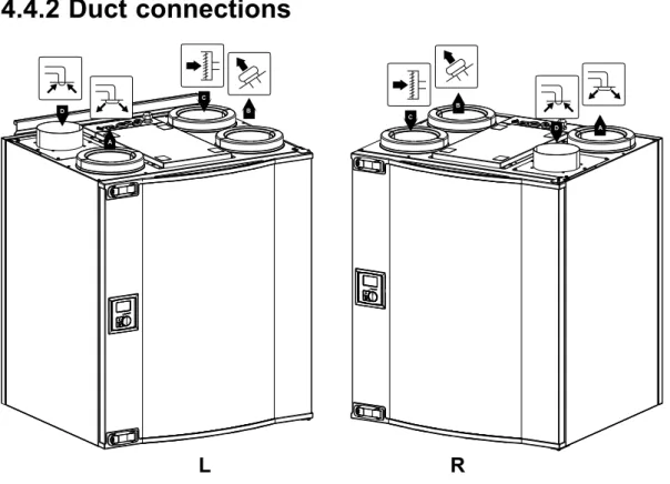
Left and Right models
Transport and storage
Technical data
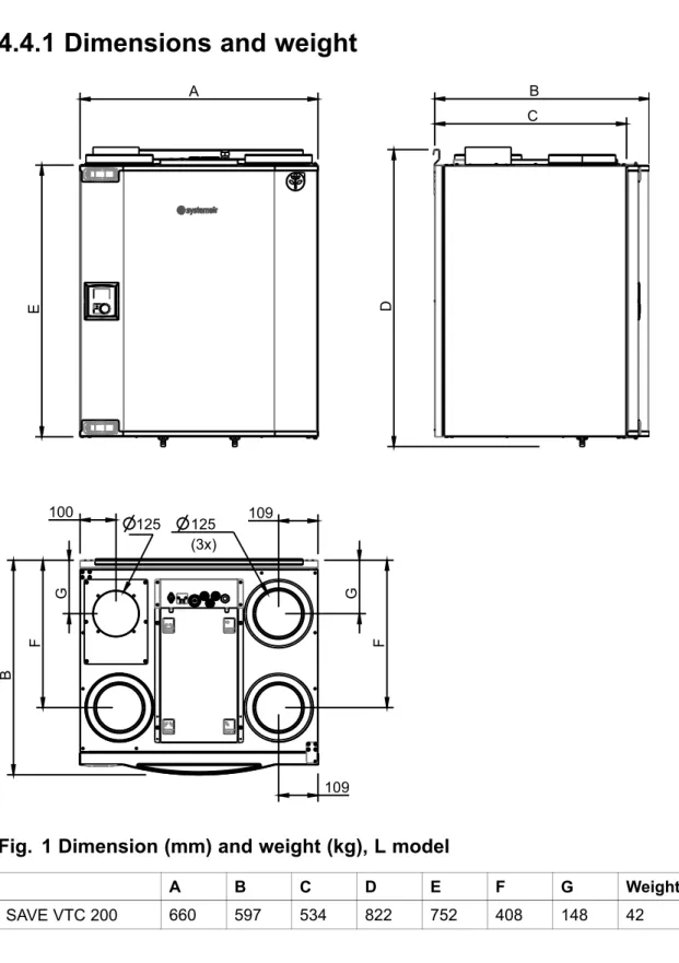
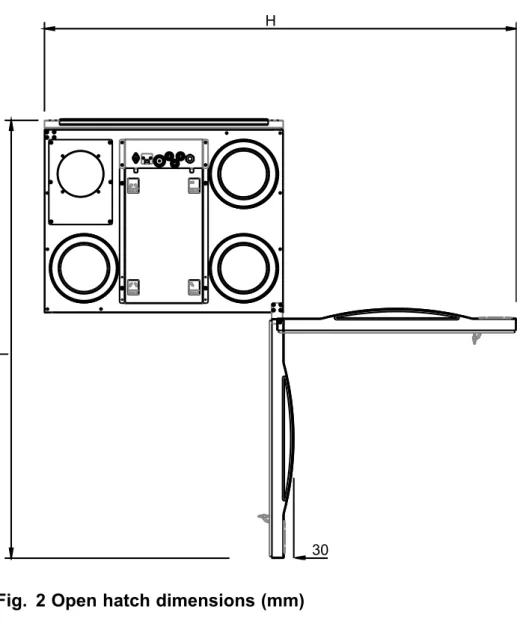
Dimensions and weight
Duct connections
Power consumption and fuse size
Unpacking
Where/how to install
Installation procedure
Add the anti-vibration list (pos. 1) to the bottom half of the back of the unit that comes with the unit. The unit must not be tilted forward so that the condensate drain can work.
Condensation drainage
Control panel
Display symbols
Temp Illustrates the current supply temperature set point (from completely empty to full symbol). It is not recommended to activate manual fan stop (set fan to OFF) in standard households. If manual fan stop is activated, the unit should be fitted with dampers in the exhaust and fresh air ducts to avoid cold drafts and the risk of condensation when the unit is stopped.
Start up wizard
Procedure
Turn the SELECT knob to select the type of fan control you prefer, Airflow(l/s or m3/h) or Speed(%) and press ENTER. The factory installed filters are of filter quality G4 for the supply air and G4 for the exhaust air filter. Here it is possible to change the nominal/high/low airflow on the exhaust and supply air fans.
Here it is possible to change the nominal / high / low fan speed on the Extract and Supply air fans.
Perform factory reset
System curves
Supply air, G4 type filter
Supply air, F7 type filter
Extract air, G4 type filter
Fan speed settings
Setting the fan speed
Use the SELECTION key for each digit and confirm with the ENTER key after each assigned digit and select "NO" so that the system is not locked.
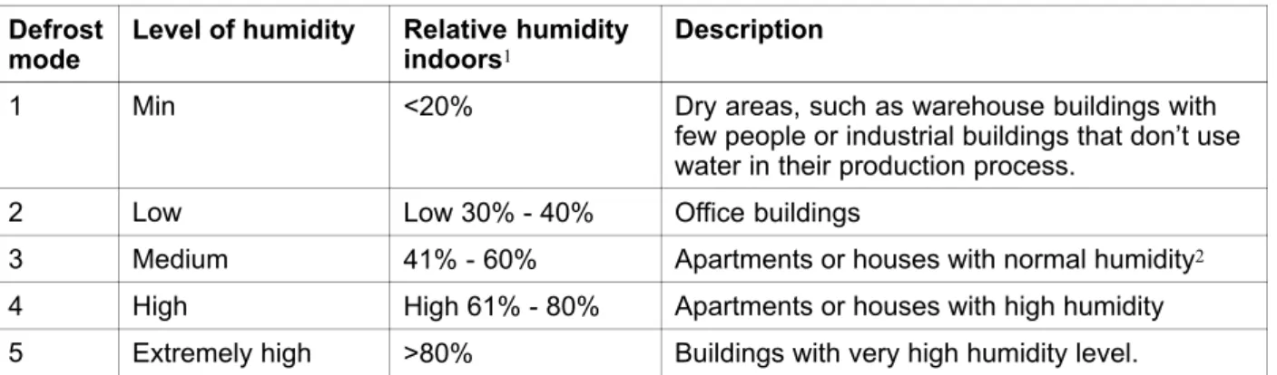
Defrost level settings
Setting the defrost level
Programming the week schedule
Ext/Force run
Extra functions
Electrical connection
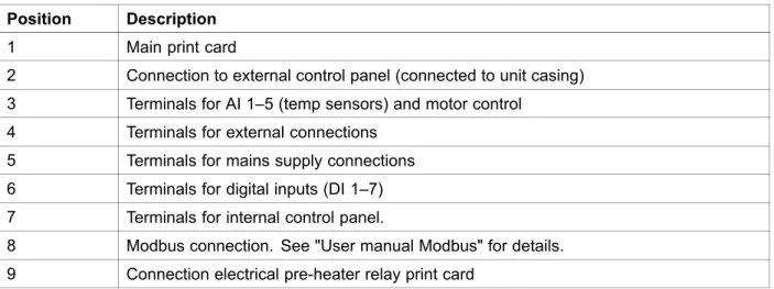
Print card layout
2 Connection to external control panel (connected unit housing) 3 Terminals for AI 1–5 (temp sensors) and motor control. 4 Terminals for external connections 5 Terminals for mains connections 6 Terminals for digital inputs (DI 1–7) 7 Terminals for internal control panel.
External connection on the print card
External connections on the unit
Connect the heat board to the main circuit board using the prepared connection on the side of each circuit board. Fixing the pre-heater relay board on the prepared spacers next to the main PCB with the supplied screws. Connect the blue power supply and the brown cables (pos 1) to the free L/N terminals on the main PCB.
Cables for power supply and bridging of the ET are included in the heatmap set. Once the preheater is installed, the unit will self-adjust to avoid going into defrost mode. Outside and exhaust dampers and silencers are installed and that the duct system is correctly connected to the unit.
Setting the temperature
Manual setting of fan speed
Manual and automatic summer mode
Cool recovery
Service menu overview
Set the day of the week and the time interval for when you want the unit to be in ON mode. Use this dialog box to define the ON and OFF function of the fans in a weekly schedule. Use this dialog box to see how the fans performed during the time (h) they were active.
Choose between levels to see the time in hours that fans were active at different levels. Reset To reset the SF and EF time in the left column for all levels. These should not be required for configuration when connected to a wireless gateway, they should only tell the unit (PCU-EC) that a sensor is available.
Setif it should be possible to turn off the fans in the unit manually from the control panel. If selected, the fans can be turned off by rotating the SELECT knob to fan idle. Indicates current analog outputs at 0–10 V to hot/cold water actuator or electric reheater and bypass damper.
When used on a bypass hatch, the unit can be forced to switch to summer operation mode (10 V). Use this dialog box to set how you want the fans to respond to 3 different digital inputs when turned on (the settings in the left column are examples). The function overrides the current fan speed settings and operates according to the settings in Service->.
Heat exchanger operating through the adjusted set point value and an active reheater has support control for the lowest set point. Active wireless DI19 and DI20 Active wireless DI1-20 are available to assign to DI1-5 and DI7 for the system in the air handling unit. DI6 is not available as an option, which is used by the system in the air handling unit.
Use this dialog box to set how aggressively you want the defrost function to work (see chapter 6.5). Information on Modbus communication and variables can be found in the Modbus user manual for residential units in the online catalog at
Warnings
Internal components
Components description
- Fans
- Filters
- Heat exchanger
- Print card
The supply air sensor (SS) at AI 1 must be replaced with a duct sensor that can be purchased as an accessory. A water reheater battery (optional), which can be purchased as an accessory, can be controlled by the analog output WH (0-10 V DC). The frost protection sensor should then be a tape on surface sensor located on the return water pipe.
If a water reheater coil is installed, we strongly recommend that you also install an outdoor air damper with a spring return actuator. A water cooler (optional) can be purchased as an accessory and controlled by the unit. If a water cooler is installed, the supply air sensor (SS) at AI 1 must be replaced with a duct sensor that can be obtained as an accessory.
Check the mains fuse in the facility distribution box and that all quick connectors (quick connectors for supply and exhaust fans) are connected in the unit. Check the analog inputs in the service menu to verify that the temperature sensors are OK (Chapter 9.5). Check that the anti-vibration pads are installed on the bottom rear of the unit.
Frost Indicates activated frost protection (in case of installed water heating coil) or activated overheating protection (in case of installed electrical reheater coil). The appliance will restart as soon as the water temperature rises +5°C above the set frost protection temperature. An activated overheating protection for an electric reheater gives an alarm in the control panel.
PbFail Fault in connection with the relay card for the electric preheater (if installed and activated).