The statement applies only to the product in the condition in which it was delivered and installed at the facility in accordance with the included installation instructions. EN 61000-6-3 Electromagnetic compatibility (EMC) – Part 6-3: Generic standards – Emission standards for residential, commercial and light industrial environments. Ensure that the power supply to the unit is disconnected before performing any maintenance or electrical work.
All electrical connections and maintenance work must be carried out by an authorized installer and in accordance with local rules and regulations. The installation of the unit and the complete ventilation system must be carried out by an authorized installer and in accordance with local rules and regulations. Although the mains supply to the device has been disconnected, there is still a risk of injury from rotating parts that have not come to a complete stop.
This product may only be operated by a person with appropriate knowledge or training in this field or under the supervision of a suitably qualified person. The manual contains basic information and recommendations regarding the design, installation, start-up and operation to ensure trouble-free operation of the unit.
General
Transport and storage
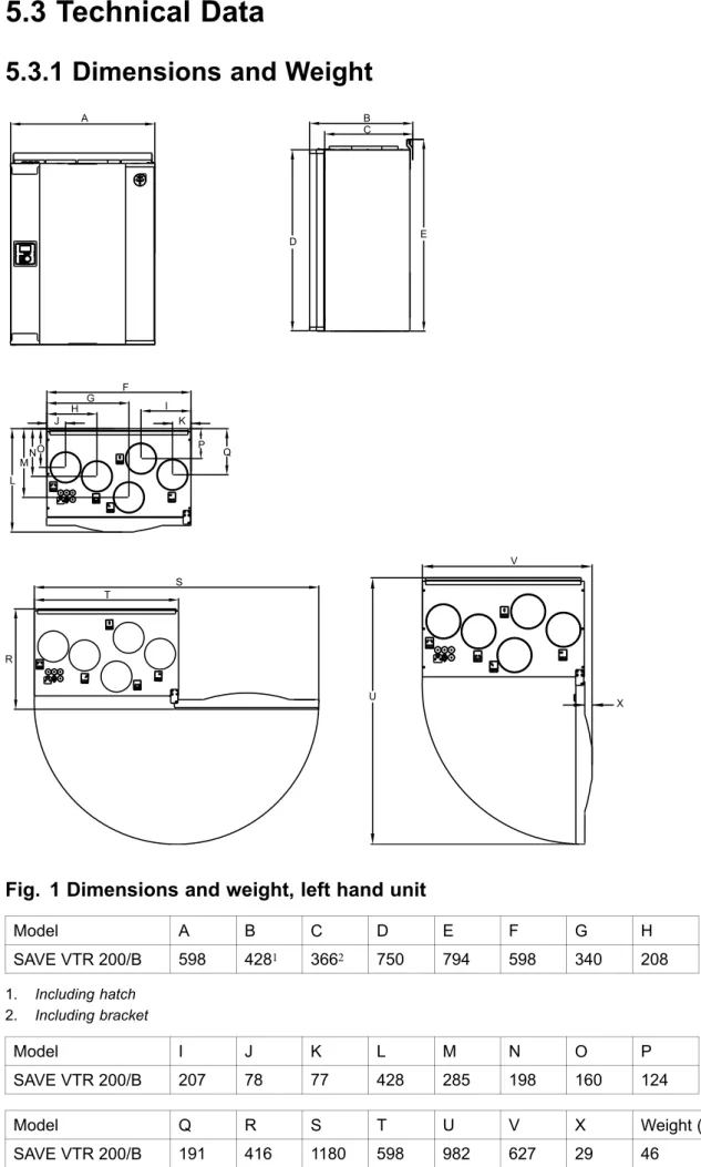
Technical Data
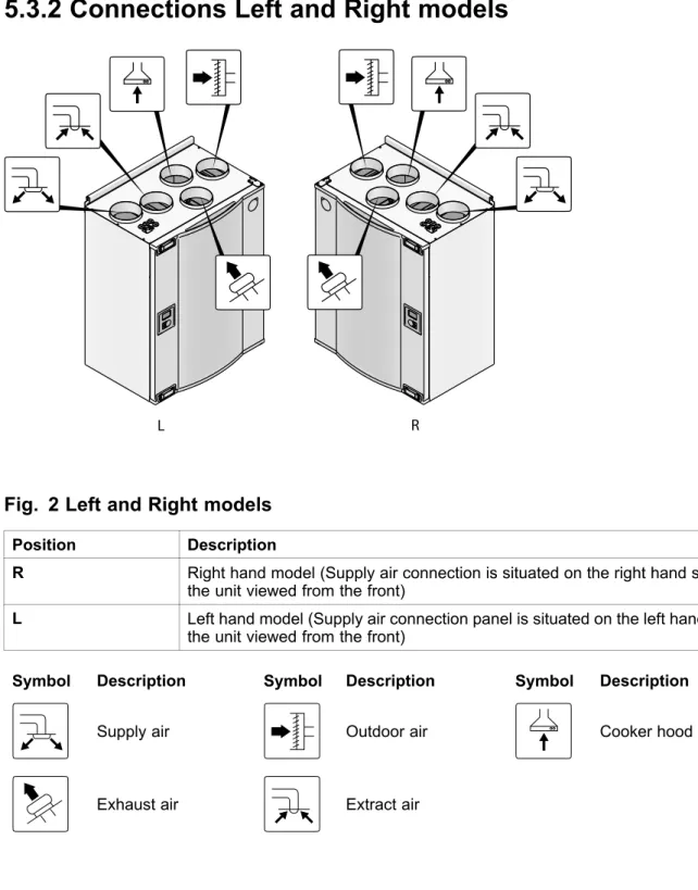
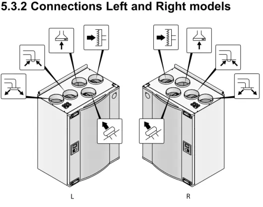
R Right-hand model (the air intake port is located on the right side of the unit when viewed from the front). L Left-hand model (the air intake connection panel is located on the left side of the unit when viewed from the front). To ensure correct and trouble-free operation, it is important that the unit is installed in accordance with these instructions.
Unpacking
Where/how to install
Installation procedure
Electrically connect the unit to the mains using the included plug and ensure that it switches on correctly.
Condensation drainage
Open the front hatch
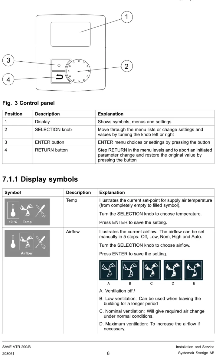
Control panel
2 SELECTION knob Scroll through the menu lists or change settings and values by turning the knob to the left or right. 3 ENTER button ENTER menu choices or settings by pressing the button. 4 RETURN button Step RETURN in the menu levels and to abort a started. Temp Illustrates the current set point for the supply air temperature (from completely empty to filled symbol).
It is not recommended to enable manual fan stop (set fan to OFF) in standard households. If manual fan stop is activated, the unit must be provided with dampers in exhaust and fresh air ducts to avoid cold drafts and risk of condensation when the unit is stopped.
Start up wizard
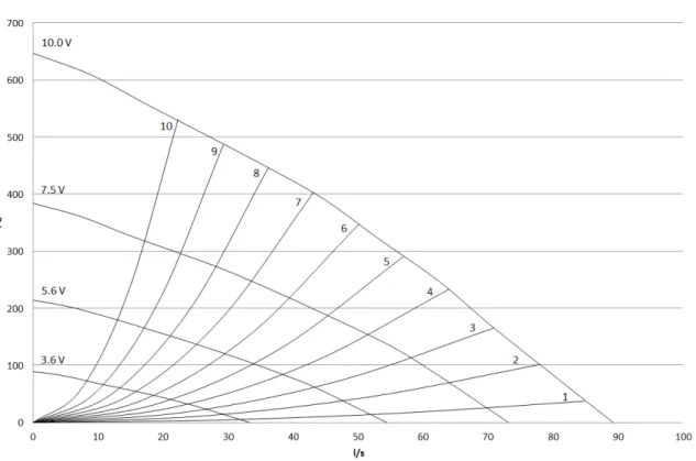
Turn the SELECT knob to select the type of fan control you prefer, System Curve(l/s) or Percentage(%) and press ENTER. This function is implemented in the unit to compensate the flow values for different system pressures. The factory installed filters are of filter quality F7 for the supply air and G3 for the exhaust air filter.
Here it is possible to change the Nominal/High/Low airflow on the Extract air fan (EF) and Supply air fan (SF). Enter the service menu by selecting the service symbol on the display and press ENTER. Use the SELECT button for each digit and confirm with the ENTER button after each set digit and choose NO to not lock the system.
System curves
Airflow settings
Use the SELECTION button for each digit and confirm with the ENTER button after each set digit and select "NO" to not lock the system.
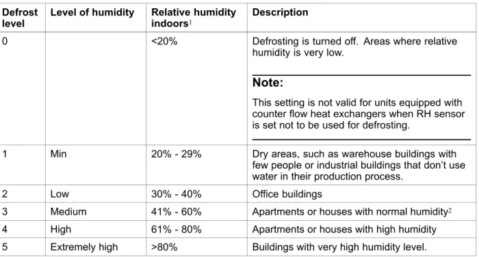
Defrost level settings
This setting is not valid for units equipped with counter flow heat exchangers when the RH sensor is set not to be used for defrosting. In new build houses it may be necessary with a higher defrost level during the first winter period.
Programming the Week schedule
Ext/Force run
Extra functions
Electrical connections
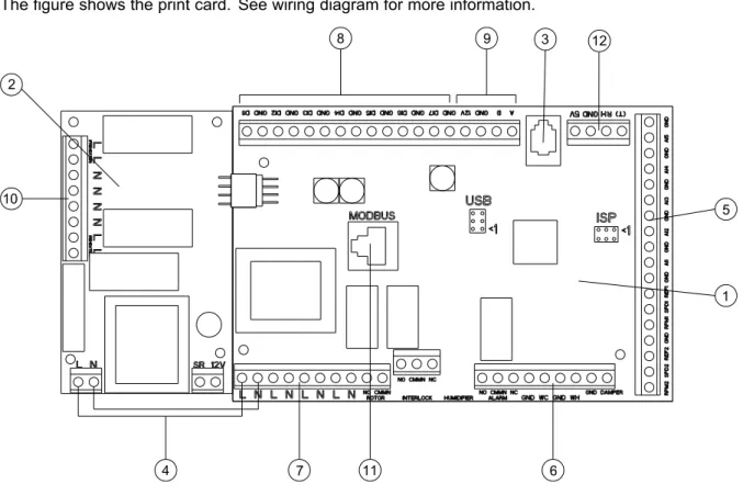
4 Mains connection between main pressure card and electric heater pressure card 5 Terminals for AI 1–5 (temp sensors) and motor control. 6 Terminals for external connections 7 Terminals for mains supply connections 8 Terminals for digital inputs (DI 1–7) 9 Terminals for internal control panel. Connection terminals for external equipment can be found on the main pressure card inside the electrical junction box.
External connections on top of the unit
Setting the temperature
Manual setting of airflow
Manual and automatic summer mode
Cool recovery
Service menu overview
Use this dialog box to program the extended time you want the unit to operate under operating conditions other than the weekly schedule. Set the day of the week and the time interval for when you want the unit to be in ON mode. Use this dialog box to define the ON and OFF function of the fans in a weekly schedule.
Use this dialog box to see how the fans have performed during the time (h) they have been active. Choose between the levels to see the time in hours the fans have been active at the different levels. If the preheater is activated and the heat exchanger control is set to "On/Off", it is strongly recommended to select defrost level 0 to avoid conflicts with defrost functions.
Set whether it should be possible to manually switch off the fans in the unit from the control panel. If Y is selected, the fans can be turned off by turning the SELECTION KNOB to empty fan. It is also possible to set how you want the fans to respond to 3 different digital inputs when they are switched on.
Set the supply fan (SF) and exhaust fan (EF) individually to off, low, nom or high for digital inputs 1–3 Set a predefined switch-off delay for the input signal. Heat exchangers operating with the adjusted set point value and an active reheater have support control for the lowest set point. Active wireless DI19 and DI20 Active wireless DI1-20 can be assigned to DI1-5 and DI7 for the system in the unit.
DI6 is not available as a selection used by the system in the air handling unit. Use this dialog to configure the intensity of the extract air humidity control, which helps to prevent moisture transfer to the supply air. Use this dialog to set how aggressively you want the defrost function to work (see section 7.5).
These settings are only present when the heat exchanger controller type is set to On/Off.
Warnings
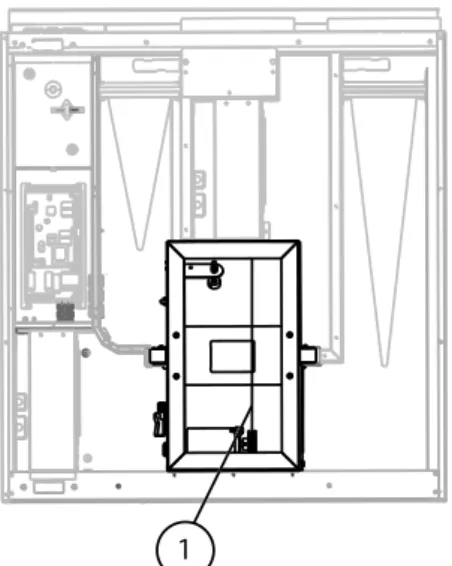
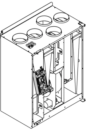
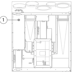
Internal components
Component descriptions
If the supply air temperature is low, this may indicate that the overheating protection has tripped. A water re-heater (optional), which can be taken as an accessory, can be controlled by the analog output WH (0-10 V DC). The water heater uses AI 4 for frost protection (OT, "Protection over heat", changes to FPS , Frost protection in the menu).
The anti-freeze sensor should be a surface mounted sensor on the return water pipe. The supply air sensor (SS) on AI 1 needs to be replaced with a duct sensor, which can be purchased as an accessory. If a battery for additional water heating is installed, we strongly recommend that you also install an outside air damper with a spring return drive.
A water cooler (optional) can be purchased as an accessory and controlled by the unit.
Trouble shooting
Alarm list
If the water reheater is configured and the frost protection has failed, an additional safety function is triggered when the supply temperature is lower than 5 °C and the outside air temperature is below 0 °C.
Replacing rotor drive belt
Use tape to secure the drive belt to the rotary heat exchanger and turn the exchanger by hand to grip the drive belt. Pull the drive belt onto the pulley and rotate the changer by hand. If the drive belt slips, the drive belt may be too long and needs to be shortened.