To repair refrigeration systems, (1-3) through (1-7) must be completed before working on the systems. All maintenance personnel and others working in the local area must be instructed in the nature of the work being carried out. If electrical components are changed, they must be fit for purpose and to the correct specifications.
This will be reported to the owner of the equipment so that all parties are aware. Before recharging the system, it should be pressure tested with the correct purge gas. Equipment must be labeled to indicate that it has been taken out of service and that the refrigerant has been removed.
In addition, a set of calibrated scales must be available and in good working order. The reclaimed refrigerant must be returned to the refrigerant supplier in the appropriate recovery cylinder and the relevant waste transfer note maintained. The evacuation process must be performed before the compressor is returned to the suppliers.
To accelerate this process, only electric heating of the compressor body is used.
SPECIFICATIONS4
5 NOISE CRITERION CURVES
6 OUTLINES AND DIMENSIONS
WIRING DIAGRAM7
8 REFRIGERANT SYSTEM DIAGRAM
The actions to take for maintenance, depending on whether the problem reoccurs in the field, are summarized in the table below.
9-1. TROUBLESHOOTING
TROUBLESHOOTING9
Current and past control codes are recorded and can be displayed on the wired remote control or the control panel of the outdoor unit. About 2 minutes after power on, the remote control cannot be operated due to system startup. 1-4 Check the pipe temperature
Remote controller transmission error (E0)/Signal reception error (E4) 1 Abnormal if main or sub remote controller con-. troller cannot receive normal transmission from the indoor unit with refrigerant address "0" for 3 minutes. 1 Abnormal if the controller board of the indoor unit cannot receive data normally from the remote controller board or other controller board of the indoor unit for 3 minutes. 3 Wrong remote control wiring 4 Faulty transceiver. remote control circuit 5 Faulty transceiver. indoor control refrigerant board circuit addresses "0".
Indoor/outdoor unit communication error (Signal reception error) 1 Abnormal if indoor controller board. cannot receive any signal normally for 6 minutes after turning on the power. Abnormal if data cannot be read normally from the non-volatile memory of the indoor controller board. board 1 Replace indoor controller board.
9-4. TROUBLESHOOTING OF PROBLEMS
3 Normal operation (Each connector on the blade motor side is disconnected or fixed blades setting by wired remote control.). 2) LED2 on the internal controller board. 2 Refrigerant address for outdoor unit is incorrect or not There are several units set in the grouping control system. 1 Check the connection of the remote control wires in the case of a double triple indoor unit system.
If the same problem occurs even if the indoor unit controller board is replaced, replace the wireless remote controller board.
9-5. EMERGENCY OPERATION
3 If the water does not drain, confirm that the check code P5 will not be displayed 10 minutes after the start of operation. Note: The drain pump for this model is driven by the internal DC motor of the control board, so it is not possible to measure the resistance between the terminals. Purple-Black: Abnormal (check P5 code) if it outputs a 0-13V square wave (5 pulses/rotation) and the rotation number is not normal.
Turn on the power while the i-see sensor connector is connected to CN4Z on the indoor controller board. A communication is made between the internal controller board and the i-see sensor board to detect the connection. Normal: When operation starts, the i-see sensor motor is driven to rotate the i-see sensor.
Note: The voltage between the terminals cannot be accurately measured as it is pulse output.
9-6. HOW TO CHECK THE PARTS
Do not pull out the connector (CNMF) of the motor with the power supply on. It causes problems with the indoor controller circuit and the fan motor.) Self-check. Remove the blower motor (Remove blower motor connector CNMF) and measure the voltage in the indoor controller circuit board. Check the method of the DC fan motor (fan motor / indoor controller circuit). loose connector, insertion error) No.
Note: If the indoor fan does not work after replacing the indoor controller board, you must also replace the fan motor. Note: If the indoor fan does not work after replacing the fan motor, you must also replace the indoor controller board.
9-7. TEST POINT DIAGRAM
Indoor controller board
The pair number settings of the wireless remote controller and indoor control PCB (J41/J42) are given in the table on the left. in the table indicates that the connecting wire is disconnected.).
9-8. FUNCTIONS OF DIP SWITCH AND JUMPER WIRE
10 FUNCTION SETTING
10-1. UNIT FUNCTION SETTING BY THE REMOTE CONTROLLER
11 SPECIAL FUNCTION
11-2. ELECTRICAL CIRCUIT (Controller board and wiring diagram (Panel))
11-2-1 DIP SW
Problem Possible cause Remedy The intake grill does not work. with operation of the remote control. The intake grille repeats raising and lowering several times while it is placed in the correct position. Lower the intake grille again and check if the filter is fitted in the correct position.
11-3. TROUBLESHOOTING
When you restart the unit to work after power off or OFF operation, the unit that was working will start working. How to set the rotation function (backup function, 2nd level power-on function)" and set the request code No. which is not the same as the current one, then set the previous request code No. 2 again) 2nd level cut -in function Overview of functions When 1. unit cannot provide sufficient capacity for extremely high demands and the actual room temperature reaches the set point (*), the 2nd unit starts working in conjunction with the 1st unit.
Once the current room temperature drops to 4°C below the set point (*), the second unit stops operation automatically. ROTATION FUNCTION (AND RESERVE FUNCTION, 2ND STAGE CUTTING FUNCTION). 1) Rotation function (and backup function). This function is only available from group control system (INDOOR UNIT : OUTDOOR UNIT=1:1) with 2 cooling groups.
The main indoor unit must be connected for the wired remote control and the transmission line (TB5) for the main unit and the sub unit must also be connected. This function cannot be set by the wireless remote control.). How to set the rotation function (Backup function, second stage lock function) You can set these functions by wired remote control.
NOTICE
9 Press the F3 or F4 button to set the desired request code number. The data is collected and displayed.
OPERATING PROCEDURE PHOTOS/FIGURES
Removing the filter
Removing the air intake grille
Removing the electrical box cover
DISASSEMBLY PROCEDURE12
Removing the indoor controller board (I.B)
Removing the electrical box
Removing the turbo fan
When assembling the turbo fan, attach it so that its tabs fit the holes of washer
- Removing the fan motor (MF)
Cross section diagram
- Removing the panel
- Removing the drain pan
- Removing the pipe temperature/liquid thermistor (TH2) and condenser/evaporator temperature thermistor (TH5)
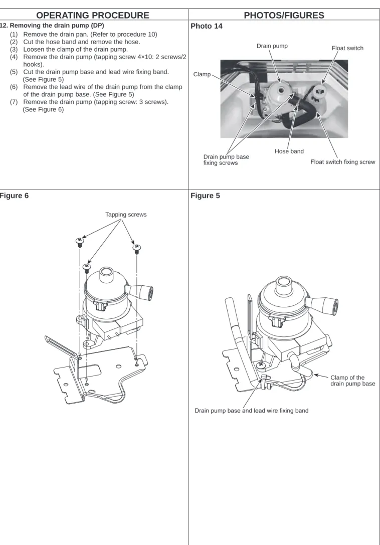
- Removing the drain pump (DP)
- Removing the float switch (FS)
- Removing the heat exchanger
Removal of Tube Temperature/Liquid Thermistor (TH2) and Condenser/Evaporator Temperature Thermistor (TH5) and Condenser/Evaporator Temperature Thermistor (TH5) (1) Remove the drain pan (Refer to Procedure 10) and. loosen the 2 clamps of the coil plate.