Standard Modular Chiller HP 1/8 compressors with CAREL driver
Application program for pCO 1 , pCO 2 , pCO 3 , pCO C and pCO XS .
User manual
Manual version: 2.6dated 11/07/08 Program code: FLSTDmMCDE
LEGGI E CONSERVA QUESTE ISTRUZIONI READ AND SAVE THESE INSTRUCTIONS
We wish to save you time and money!
We can assure you that the thorough reading of this manual will guarantee correct installation and safe use of the product described.
IMPORTANT WARNINGS
BEFORE INSTALLING OR HANDLING THE DEVICE, PLEASE CAREFULLY READ AND FOLLOW THE INSTRUCTIONS CONTAINED IN THIS MANUAL.
The instrument this software is intended for has been expressly designed to operate without risks for the established purposes, provided that:
the software is installed, programmed, used and maintained by qualified personnel in full accordance with the instructions contained in this manual;
all conditions specified and contained in the appliance installation and operating manual are met.
CONTENTS
1. Introduction ...7
1.1 Main new features in version 2.0... 7
1.2 Introduction and functions performed by the program ... 7
1.3 Compatible hardware ... 7
2. The user terminal ...8
2.1 Type and operation... 8
2.2 LEDs... 8
2.3 Functions of the buttons ... 9
3. pLAN management between boards...11
3.1 How to assign the pLAN addresses ... 11
4. Selecting the language...12
5. Starting for the first time ...12
5.1 Switching the unit on/off ... 12
6. List of inputs/outputs ...13
6.1 Chiller-only units, configuration “0”... 13
6.2 Chiller unit with freecooling, configuration “1” ... 14
6.3 Chiller units with heat pump, configuration “2” ... 15
6.4 Chiller units with heat pump and total heat recovery, configuration “3” 16 6.5 Cooling-only condensing units, configuration “4” ... 17
6.6 Condensing units with heat pump, configuration “5”... 18
6.7 Chiller-only units, configuration “6”... 19
6.8 Chiller / heat pump units with reversal on water circuit, configuration “7”... 20
6.9 Chiller-only units, configuration “8”... 21
6.10 Chiller units with freecooling, configuration “9” ... 22
6.11 Chiller units with heat pump, configuration “10”... 23
6.12 Chiller units with heat pump and total recovery, configuration “11” ... 24
6.13 Air/air condensing units, configuration “12”... 25
6.14 Chiller units with heat pump and condenser, configuration “13”... 26
6.15 Chiller-only units, configuration “14”... 27
6.16 Cooling/heating units with reversal on the water circuit, configuration “15”... 28
6.17 Chiller-only units, configuration “16”... 29
6.18 Chiller units with freecooling, configuration “17” ... 30
6.19 Chiller units with heat pump, configuration “18”... 31
6.20 Chiller units with heat Pump and total heat recovery, configuration “19”... 32
6.21 Condensing units, configuration “20”... 33
6.22 Condensing units with heat pump, configuration “21”... 34
6.23 Chiller-only units, configuration “22”... 35
6.24 Cooling/heating units with reversal on the water circuit, configuration “23”... 36
6.25 Air/water units with maximum 4 hermetic compressors for PCO
XS... 37
7. List of parameters and default values ...38
8. Screens ...45
8.1 List of the screens ... 45
9. EVD200 electronic expansion valve...48
9.1 Driver parameters... 48
9.2 Special “Ignore” function... 49
10. Control ...50
10.1 Control set point ... 50
10.2 Temperature control ... 50
10.3 Inlet temperature control... 50
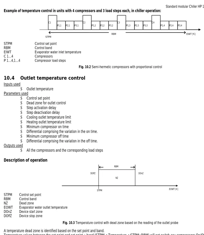
10.4 Outlet temperature control... 51
11. Compressor control...53
11.1 Enable compressors from the screen... 53
11.2 Compressor rotation... 53
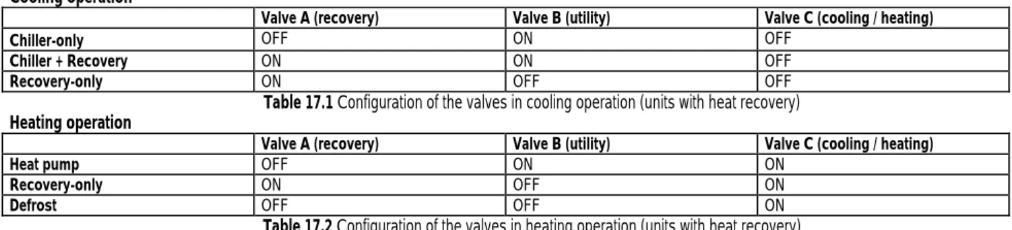
17. Control of heat recovery units...63
17.1 Recovery priority... 63
17.2 Utility priority ... 63
18. Freecooling control ...64
18.1 Activation of the freecooling function... 64
18.2 Freecooling thermostat... 64
18.3 Deactivation of the freecooling function ... 65
18.4 ON/OFF freecooling valve... 65
18.5 ON/OFF freecooling valve with stepped condenser control... 66
18.6 ON/OFF freecooling valve with condenser control by inverter... 67
18.7 0 to 10 V freecooling valve ... 67
18.8 0 to 10 V freecooling valve with condenser control by steps ... 67
18.9 0 to 10 V freecooling valve with condenser control by inverter... 68
18.10 Proportional + integral control ... 68
19. Antifreeze control ...69
20. Pump control...70
20.1 Burst operation ... 70
20.2 Pump rotation ... 70
21. Installation start-up mode ...70
22. Accessory functions...71
22.1 Temperature set point compensation... 71
22.2 Time bands... 71
22.3 Time bands with different set points... 71
23. Alarms...72
23.1 General description ... 72
23.2 Table of alarms... 73
24. Alarm log ...75
24.1 Basic log ... 75
24.2 Advanced log... 75
25. Supervisor ...76
26. Other protocols ...4
26.1 RS232 protocol (connection via analogue modem) ... 4
26.2 GSM protocol... 4
1. Introduction
1.1 Main new features in version 2.0
New functions:
1. Implemented compatibility with pCO
3; 2. improved management of customised rotation;
3. burst pumps function;
4. automatic cooling/heating changeover.
1.2 Introduction and functions performed by the program
Type of units controlled
Cooling only condensing unit Condensing unit with heat pump Air / water chiller only Air / water chiller + freecooling Air / water total recovery Air / water chiller + heat pump
Air / water chiller only Air / water chiller + heat pump (reversal on water circ.).
Type of control
- Proportional or proportional + integral control on evaporator water inlet temperature probe.
- Dead zone control by time on evaporator water outlet probe Type of compressors
From 1 to 8 Tandem hermetic compressors 4 compressors for each pCO* board, excluding
pCOXS
From 1 to 8 Semi-hermetic compressors with max. 1 load step 2 compressors for each pCO* board, excluding pCOXS
From 1 to 4 Semi-hermetic compressors with max. 3 load steps 1 compressor for each pCO* board, excluding pCOXS Rotation of compressor calls
- Rotation with FIFO logic, LIFO logic, based on the operating hours of each compressor, custom (logic set by the user) Condenser control
- Condenser control according to temperature or pressure
- Fans can be managed in ON/OFF mode or by a 0 to 10 V modulating signal.
Type of defrost
- Global defrosting of all the pCO* units connected to the network: Independent / Simultaneous / Separate.
- Local defrosting of the individual pCO* unit: Separate / Simultaneous Safety devices on each refrigerant circuit
- High pressure (pressure switch/transducer) - Low pressure (pressure switch)
- Differential oil pressure switch - Compressor thermal overload - Condenser fan thermal overload.
System safety devices
- Serious alarm input (stops the whole unit), available on both MASTER and SLAVE units - Flow switch (stops the whole unit), available on both MASTER and SLAVE units - Pump thermal overload (stops the whole unit)
- Remote on/off input without alarm signal Other functions
- Multi-language management (Italian, English, German, French) - Alarm logging
- Management of pGD0*, external and built-in LCD terminals (on pCO²/pCO
3and pCO
XS) - Management of ratiometric probe for pressure control (on pCO¹/pCO
3and pCO
XS) - Management of a phase control inverter (on pCO¹ and pCO
XS)
- EVD driver for electronic valve control
- Time band management with change of set point or ON/OFF, and Management of set point compensation based on the outside temperature - Management of GSM and analogue modems, and Management of pump rotation
- Management of fan coil enabling signal.
2. The user terminal
2.1 Type and operation
Three types of terminal are envisaged:
1. PGD0/semi-graphic/6 buttons/4 rows - 20 columns/connection with telephone cable 2. LCD/15 buttons/4 rows - 20 columns/connection with telephone cable
3. Built-in/6 buttons/4 rows - 20 columns (pCO²- pCO
3only)/display on board
The user terminal can be used to perform all the operations allowed by the program, display the operating conditions of the unit at all times, and set the parameters.
It can be disconnected from the main board, and in fact is not required for operation.
2.2 LEDs
2.2.1 PGD0 terminal with 6 buttons
LED Colour Description
[ ] button (Alarm) Red On – One or more active alarm conditions Prg button Yellow On – Unit on
Flashing – Unit off from supervisor or digital input All the LEDs not described and located underneath the remaining 4 buttons indicate the correct power supply to the instrument.
Together with the backlighting on the display, these will be switched off if no button is pressed on the keypad for 5 minutes.
2.2.2 LCD terminal with15 buttons
Each button has a green LED indicating the specific group of parameters selected during the operations to display/modify the operating parameters.
The silicone rubber buttons have three different coloured LEDs, whose meaning is specified in the following table
LED Colour Description
[ On/Off ] button Green On – Unit on
Flashing – Unit off from supervisor or digital input [ ] button ( Alarm ) Red On – One or more active alarm conditions [ ] button ( Enter ) Yellow On – Instrument correctly powered 2.2.3 Built-In terminal with 6 buttons
Given the number of buttons and LEDs available, these have general meanings, as described below:
LED Colour Description
[ ] button (Alarm)
Red On – One or more active alarm conditions [ ] button
(Enter) Yellow On – Unit on
Flashing – Unit off from supervisor or digital input
[ Prg ] button Green On – Displaying/modifying the operating parameters
[ Esc] button Green On – Main menu parameters displayed
2.3 Functions of the buttons
2.3.1 PGD0 terminal with 6 buttons
Button Description
ALARM displays the alarms, mutes the buzzer and deletes the active alarms
UP if the cursor is in the home position (top left corner), scrolls up the screens in the same group; if the cursor is in a setting field, increases the value
DOWN if the cursor is in the home position (top left corner), scrolls down the screens in the same group; if the cursor is in a setting field, decreases the value
ENTER used to move the cursor from the home position (top left corner) to the setting fields, in the setting fields confirms the set value and moves to the next parameter
PRG accesses the menu for selecting the group of parameters to be displayed/modified (access to the parameters is confirmed by pressing the [Enter] button)
PRG + ENTER temporarily display the pLAN serial address of the board
ESC + ENTER pressed at the same time for 20 seconds access the screen for switching the unit On/Off 2.3.2 pGD0 terminal with 15 buttons
Button Description
MENU From any point of the user interface (with the exception of the manufacturer group of parameters) returns to the Main menu screen (M0) displaying the unit status, readings of the control probes and operating mode.
In the group of manufacturer parameters, organised into nested sub-groups, returns to screen for selecting the parameters.
MAINTENANCE
Goes to the first screen of Maintenance parameters (A0)
The Maintenance parameters are used to check the operating status of devices and the probes, calibrate the readings and run manual operations
PRINTER Temporarily display the pLAN serial address of the board
ALARM UP
PRG ENTER
ESC DOWN
Button Description
RED with the unit off enables heating management in the unit configurations where chiller / heat pump operation is envisaged.
BLUE with the unit off enables cooling management in the unit configurations where chiller / heat pump operation is envisaged
Silicone rubber buttons
Button Description
1 ON/OFF switches the unit on/off
2 ALARM displays the alarms, mutes the buzzer and deletes the active alarms
3 UP ARROW if the cursor is in the home position (top left corner), scrolls up the screens in the same group; if the cursor is in a setting field, increases the value
4 DOWN
ARROW if the cursor is in the home position (top left corner), scrolls down the screens in the same group; if the cursor is in a setting field, decreases the value
5 ENTER used to move the cursor from the home position (top left corner) to the setting fields, in the setting fields confirms the set value and moves to the next parameter
2.3.3 Built-In terminal with 6 buttons
Button Description
ALARM displays the alarms, mutes the buzzer and deletes the active alarms
UP if the cursor is in the home position (top left corner), scrolls up the screens in the same group; if the cursor is in a setting field, increases the value
DOWN if the cursor is in the home position (top left corner), scrolls down the screens in the same group; if the cursor is in a setting field, decreases the value
ENTER used to move the cursor from the home position (top left corner) to the setting fields, in the setting fields confirms the set value and moves to the next parameter
PRG accesses the menu for selecting the group of parameters to be displayed/modified (access to the parameters is confirmed by pressing the [Enter] button)
PRG + ENTER temporary display of the board pLAN serial address
ESC + ENTER pressed at the same time for 20 seconds access the screen for switching the unit On/Off
ALARM PRG ESC
DOWN UP ENTER
3. pLAN management between boards
The pLAN network identifies a physical connection between the boards (pCO
1, pCO
2,pCO
3) and the external terminals.
pLAN=.CO L.ocal A.rea N.etwork. The purpose of the pLAN network connection between the boards is to exchange variables, according to the logic decided by the program, so as the units can operate together.
The variables exchanged between the boards are established by the program, as is the direction of exchange, and therefore there are no user settings; the only operation required by the user involves the electrical connections.
Below is a diagram with all the components connected in the pLAN:
pCO
xpCO
xpCO
xpCO
x EVD200 EVD200EVD200 EVD200 EVD200 EVD200 EVD200 EVD200
1 3 5 7 9 11
12 8 10
4 6 2
32
EVD200 EVD200
EVD200 EVD200
14 16
13 15
pLAN
EVD200 EVD200
EVD200 EVD200
21
23 19 17
24 22 20 18
The main screen M0 shows the address of the board connected in the bottom left corner. The terminal with address 32 can display all the boards without needing the other terminals.
pCO TERMINAL EVD200 cool heat EVD200 heat
UNIT 1 1 21 5-7 6-8
UNIT 2 2 22 9-11 10-12
UNIT 3 3 23 13-15 14-16
UNIT 4 4 24 17-19 18-20
3.1 How to assign the pLAN addresses
The pLAN addresses must be unique and set according to the figure shown above. There are various methods for assigning the pLAN address.
3.1.1 PGD0 terminal
To set the address of a PGD terminal (the default value is 32), proceed as follows:
1. Power up the terminal
2. Press the Up + Down + Enter buttons until the “display address setting” screen is displayed 3. Enter the numeric pLAN address with the Up and Down buttons and then confirm by pressing Enter 4. The “No link” screen will be displayed
5. If the “No Link” screen is not displayed, press Up + Down + Enter again 6. Once the “display address setting” screen is displayed, press Enter 3 times When the “adr Priv/shard” screen is displayed, set the correct values and confirm with “YES”
3.1.2 Setting the address on the pCO
1- pCO
3Description of the operations to be completed for setting the pLAN address on the pCO¹ and pCO
3boards:
1. Power down the pCO* board and connect a 4x20 LCD terminal / PGD0 terminal with pLAN address "0".
2. Power up the pCO* board, by holding the Alarm + Up buttons until a screen appears.
3. When the “pLAN Address” screen is shown, follow the operations shown, i.e. enter the number (1,2,3…) of the pLAN address with the Up and Down buttons and then confirm by pressing Enter.
4. Power down the pCO* board.
5. If necessary, assign the correct pLAN address to the external terminal.
6. Power up the pCO* board.
4. Selecting the language
When the unit is started, as default a screen is displayed where the language to be used can be selected.
This screen remains active for 30 seconds, after which the application automatically skips to the main menu (screen M0).
This function can be deactivated. To do this simply : 1. Go to the Program branch (screen P0) 2. Set the correct password.
3. Go to the Various parameters sub-branch
4. Press the down arrow button until reaching screen “R9”
5. Choose “N” for the item “Display language screen” on power-up.
In any case, the language can be changed at any time. To do this, simply go to screen “A2” in the “MAINT” branch.
5. Starting for the first time
After having checked the connections between the various boards and terminals, power up the pCO* board/boards. On power-up, the software automatically installs the default values chosen by CAREL for the chiller and driver configuration parameters. This section explains how to restore the default values and to return to the starting conditions. When starting for the first time, this operation is not required.
The following procedure is used to restore all the configuration parameters to the default values selected by CAREL.
CAUTION! this procedure irreversibly deletes any programming performed by the user.
As resetting the default values is an operation that involves each pCO* board, when more than one board is present, the procedure must be repeated for the all the boards. The procedure is identical for all the boards. Proceed as follows:
• press the “menu” and “prog” buttons on the LCD terminal at the same time (go to the manufacturer branch on the PGD0 terminal). When pressed, the LEDs corresponding to the “menu” and “prog” buttons will come on;
• enter the password using the “arrow” buttons and press enter : scroll the menu and enter the initialisation submenu.
+---+
¦Insert Z0¦
¦manufactory ¦
¦password ¦
¦ 0000 ¦ +---+
• enter the “Initialisation” branch from the default installation screen:
+---+
¦Reset all V0¦
¦parameters ¦
¦to default values N¦
¦Please wait... ¦ +---+
• press the “enter” button so as to position the cursor over the letter “N”, and using the arrow buttons change this to “Y”; the message “please wait...”
will appear; after a few seconds this disappears: at this stage, the default values have been installed completely.
5.1 Switching the unit on/off
There are two ways of switching the unit on/off:
1. System On/Off 2. Circuit On/Off
The unit status can be controlled from the keypad, digital input (this function can be enabled) and supervisor (this function can be enabled)
Switching the unit on/off from the keypad using the ON/OFF button has priority over the other modes; when pressing the button the corresponding green LED will be switched on/off, depending on the status. With the PGD0 or Built-in terminal, press “PRG”, scroll the menu to “Unit ON-OFF”, press “ENTER” to enter screen M2 and then switch the unit on/off.
The unit can be switched on/off from the supervisor and/or digital input only if switched on from the keypad; switching the unit off from the supervisor and/or digital
input is signalled by the flashing of the green LED corresponding to the ON/OFF button and by a special message on the main menu screen.
6. List of inputs/outputs
Following is a list of the inputs and outputs for each the type of unit; each unit type has been given a number.
This number is the main parameter of the program, and can be selected in the manufacturer menu.
6.1 Chiller-only units, configuration “0”
AIR/WATER units with maximum 8 tandem hermetic compressors.
DIGITAL INPUTS
No. pCO
2/ pCO
3MEDIUM pCO
1MEDIUM pCO
CMEDIUM
Master (address 1) Slaves (address 2) Master (address 1) Slaves (address 2) Master (address 1) Slaves (address 2) ID 1
Serious alarm Serious alarm (can be enabled) Serious alarm Serious alarm (can be enabled) Serious alarm Serious alarm (can be enabled)ID 2
Evaporator flow switch Evap. flow switch (can beenabled) Evaporator flow switch Evap. flow switch (can be
enabled) Evaporator flow switch Evap. flow switch (can be enabled)
ID 3
Remote ON/OFF Remote ON/OFF Remote ON/OFFID 4
Pump thermal overload Pump 2 thermal overload Pump thermal overload Pump 2 thermal overload Pump thermal overloadID 5
Low press. switch 1 Low press. switch 3 Low press. switch 1 Low press. switch 3 Low press. switch 1 Low press. switch 3ID 6
Comp. 1 thermal overload Comp. 5 thermal overload Comp. 1 thermal overload Comp. 5 thermal overload Comp. 1 thermal overload Comp. 5 thermal overloadID 7
Comp. 2 thermal overload Comp. 6 thermal overload Comp. 2 thermal overload Comp. 6 thermal overload Comp. 2 thermal overload Comp. 6 thermal overloadID 8
Low press. switch 2 Low press. switch 4 Low press. switch 2 Low press. switch 4 Low press. switch 2 Low press. switch 4ID 9
Comp. 3 thermal overload Comp. 7 thermal overload Comp. 3 thermal overload Comp. 7 thermal overload Comp. 3 thermal overload Comp. 7 thermal overloadID10
Comp. 4 thermal overload Comp. 8 thermal overload Comp. 4 thermal overload Comp. 8 thermal overload Comp. 4 thermal overload Comp. 8 thermal overloadID11
High press. switch 1 High press. switch 3ID12
High press. switch 2 High press. switch 4ID13
High press. switch 1 High press. switch 3 High press. switch 1 High press. switch 3ID14
High press. switch 2 High press. switch 4 High press. switch 2 High press. switch 4ANALOGUE INPUTS
No. pCO
2/ pCO
3MEDIUM pCO
1MEDIUM pCO
CMEDIUM
Master (address 1) Slaves (address 2) Master (address 1) Slaves (address 2) Master (address 1) Slaves (address 2)
B1
Cond. temp. circuit 1 Cond. temp. circuit 3 Outside set point Water inlet temp.B2
Cond. temp. circuit 2 Cond. temp. circuit 4 Water outlet temp. 1 Water outlet temp. 2B3
Outside set point High pressure circuit 1 High pressure circuit 3 Cond. temp. circuit 1 Cond. temp. circuit 3B4
Water inlet temp. High pressure circuit 2 High pressure circuit 4 Cond. temp. circuit 2 Cond. temp. circuit 4B5
Water outlet temp. 1 Water outlet temp. 2 Water inlet temp. Outside set pointB6
Water outlet temp. 1 Water outlet temp. 2B7
High pressure circuit 1 High pressure circuit 3 Cond. temp. circuit 1 Cond. temp. circuit 3 High pressure circuit 1 High pressure circuit 3B8
High pressure circuit 2 High pressure circuit 4 Cond. temp. circuit 2 Cond. temp. circuit 4 High pressure circuit 2 High pressure circuit 4DIGITAL OUTPUTS
No. pCO
2/ pCO
3MEDIUM pCO
1MEDIUM pCO
CMEDIUM
Master (address 1) Slaves (address 2) Master (address 1) Slaves (address 2) Master (address 1) Slaves (address 2)
NO1
Compressor 1 Compressor 5 Compressor 1 Compressor 5 Evap. pump 1NO2
Compressor 2 Compressor 6 Compressor 2 Compressor 6 Compressor 1 Compressor 5NO3
Liq. solenoid circuit 1 Liq. solenoid circuit 3 Liq. solenoid circuit 1 Liq. solenoid circuit 3 Compressor 2 Compressor 6NO 4
Compressor 3 Compressor 7 Compressor 3 Compressor 7 Liq. solenoid circuit 1 Liq. solenoid circuit 3NO 5
Compressor 4 Compressor 8 Compressor 4 Compressor 8NO 6
Liq. solenoid circuit 2 Liq. solenoid circuit 4 Liq. solenoid circuit 2 Liq. solenoid circuit 4 Compressor 3 Compressor 7NO 7
Evap. pump 1 Evap. pump 2. / Disable fan coil Evap. pump 1 Evap. pump 2. / Disable fan coil Compressor 4 Compressor 8NO 8
General alarm General alarm General alarm General alarm Liq. solenoid circuit 2 Liq. solenoid circuit 4NO 9
Cond. fan 1 circuit 1 Cond. fan 1 circuit 3 Cond. fan 1 circuit 1 Cond. fan 1 circuit 3NO10
Cond. fan 1 circuit 2 or Cond.fan 2 circuit 1 Cond. fan 1 circuit 4 or Cond. fan
2 circuit 3 Cond. fan 1 circuit 2 or Cond. fan
2 circuit 1 Cond. fan 1 circuit 4 or Cond. fan
2 circuit 3 Antifreeze heater 1 Antifreeze heater 2
NO11
Antifreeze heater 1 Antifreeze heater 2 Antifreeze heater 1 Antifreeze heater 2 General alarm General alarmNO12
Cond. fan 1 circuit 1 Cond. fan 1 circuit 3NO13
Cond. fan 1 circuit 2 or Cond.fan 2 circuit 1 Cond. fan 1 circuit 4 or Cond. fan 2 circuit 3
ANALOGUE OUTPUTS
No. pCO
2/ pCO
3MEDIUM pCO
1MEDIUM pCO
CMEDIUM
Master (address 1) Slaves (address 2) Master (address 1) Slaves (address 2) Master (address 1) Slaves (address 2)
6.2 Chiller unit with freecooling, configuration “1”
AIR/WATER units with maximum 8 tandem hermetic compressors.
DIGITAL INPUTS
No. pCO
2/ pCO
3MEDIUM pCO
1MEDIUM pCO
CMEDIUM
Master (address 1) Slave (address 2) Master (address 1) Slave (address 2) Master (address 1) Slave (address 2) ID 1
Serious alarm Serious alarm (can be enabled) Serious alarm Serious alarm (can be enabled) Serious alarm Serious alarm (can be enabled)ID 2
Evaporator flow switch Evap. flow switch (can beenabled) Evaporator flow switch Evap. flow switch (can be
enabled) Evaporator flow switch Evap. flow switch (can be enabled)
ID 3
Remote ON/OFF Remote ON/OFF Remote ON/OFFID 4
Pump 1 thermal overload Pump 2 thermal overload Pump thermal overload Pump 2 thermal overload Pump thermal overloadID 5
Low press. switch 1 Low press. switch 3 Low press. switch 1 Low press. switch 3 Low press. switch 1 Low press. switch 3ID 6
Comp. 1 thermal overload Comp. 5 thermal overload Comp. 1 thermal overload Comp. 5 thermal overload Comp. 1 thermal overload Comp. 5 thermal overloadID 7
Comp. 2 thermal overload Comp. 6 thermal overload Comp. 2 thermal overload Comp. 6 thermal overload Comp. 2 thermal overload Comp. 6 thermal overloadID 8
Low press. switch 2 Low press. switch 4 Low press. switch 2 Low press. switch 4 Low press. switch 2 Low press. switch 4ID 9
Comp. 3 thermal overload Comp. 7 thermal overload Comp. 3 thermal overload Comp. 7 thermal overload Comp. 3 thermal overload Comp. 7 thermal overloadID10
Comp. 4 thermal overload Comp. 8 thermal overload Comp. 4 thermal overload Comp. 8 thermal overload Comp. 4 thermal overload Comp. 8 thermal overloadID11
High press. switch 1 High press. switch 3ID12
High press. switch 2 High press. switch 4ID13
High press. switch 1 High press. switch 3 High press. switch 1 High press. switch 3ID14
High press. switch 2 High press. switch 4 High press. switch 2 High press. switch 4ANALOGUE INPUTS
No. pCO
2/ pCO
3MEDIUM pCO
1MEDIUM pCO
CMEDIUM
Master (address 1) Slave (address 2) Master (address 1) Slave (address 2) Master (address 1) Slave (address 2)
B1
Cond. temp. circuit 1 Cond. temp. circuit 3 Outside temperature Water inlet temp.B2
Cond. temp. circuit 2 Cond. temp. circuit 4 Freecooling temperature Water outlet temp. 1 Water outlet temp. 2B3
Outside temperature High pressure circuit 1 High pressure circuit 3 Cond. temp. circuit 1 Cond. temp. circuit 3B4
Water inlet temp. High pressure circuit 2 High pressure circuit 4 Cond. temp. circuit 2 Cond. temp. circuit 4B5
Water outlet temp. 1 Water outlet temp. 2 Water inlet temp. Outside temperatureB6
Freecooling temperature Water outlet temp. 1 Water outlet temp. 2 Freecooling temperatureB7
High pressure circuit 1 High pressure circuit 3 Cond. temp. circuit 1 Cond. temp. circuit 3 High pressure circuit 1 High pressure circuit 3B8
High pressure circuit 2 High pressure circuit 4 Cond. temp. circuit 2 Cond. temp. circuit 4 High pressure circuit 2 High pressure circuit 4DIGITAL OUTPUTS
No. pCO
2MEDIUM pCO
1MEDIUM pCO
CMEDIUM
Master (address 1) Slave (address 2) Master (address 1) Slave (address 2) Master (address 1) Slave (address 2)
NO1
Compressor 1 Compressor 5 Compressor 1 Compressor 5 Evap. pump 1NO2
Compressor 2 Compressor 6 Compressor 2 Compressor 6 Compressor 1 Compressor 5NO3
Liq. solenoid circuit 1 Liq. solenoid circuit 3 Liq. solenoid circuit 1 Liq. solenoid circuit 3 Compressor 2 Compressor 6NO 4
Compressor 3 Compressor 7 Compressor 3 Compressor 7 Liq. solenoid circuit 1 Liq. solenoid circuit 3NO 5
Compressor 4 Compressor 8 Compressor 4 Compressor 8NO 6
Liq. solenoid circuit 2 Liq. solenoid circuit 4 Liq. solenoid circuit 2 Liq. solenoid circuit 4 Compressor 3 Compressor 7NO 7
Evap. pump 1 Evap. pump 2. / Disable fancoil Evap. pump 1 Evap. pump 2. / Disable fan coil Compressor 4 Compressor 8
NO 8
General alarm General alarm General alarm General alarm Liq. solenoid circuit 2 Liq. solenoid circuit 4NO 9
Cond. fan 1 circuit 1 Cond. fan 1 circuit 3 Cond. fan 1 circuit 1 Cond. fan 1 circuit 3 Cond. fan 1 circuit 2 or Cond.fan 2 circuit 1 Cond. fan 1 circuit 4 or Cond. fan 2 circuit 3
NO10
ON/OFF freecooling valve Cond. fan 1 circuit 4 or Cond.fan 2 circuit 3 ON/OFF freecooling valve Cond. fan 1 circuit 4 or Cond. fan
2 circuit 3 Antifreeze heater 1 Antifreeze heater 2
NO11
Antifreeze heater 1 Antifreeze heater 2 Antifreeze heater 1 Antifreeze heater 2 General alarm General alarmNO12
Cond. fan 1 circuit 1 Cond. fan 1 circuit 3NO13
Cond. fan 1 circuit 2 or Cond. fan2 circuit 1 Cond. fan 1 circuit 4 or Cond.
fan 2 circuit 3 Cond. fan 1 circuit 2 or Cond. fan
2 circuit 1 Cond. fan 1 circuit 4 or Cond. fan
2 circuit 3 ON/OFF freecooling valve Cond. fan 1 circuit 4 or Cond. fan 2 circuit 3
ANALOGUE OUTPUTS
No. pCO
2/pCO
3MEDIUM pCO
1MEDIUM pCO
CMEDIUM
Master (address 1) Slave (address 2) Master (address 1) Slave (address 2) Master (address 1) Slave (address 2)
Y1
Modul. freecooling valve Modul. freecooling valve Cond. fan 1 inverter Cond. fan 3 inverterY2
Modul. freecooling valve Cond. fan 4 inverter6.3 Chiller units with heat pump, configuration “2”
AIR/WATER units with maximum 8 tandem hermetic compressors.
DIGITAL INPUTS
No. pCO
2/pCO
3MEDIUM pCO
1MEDIUM pCO
CMEDIUM
Master (address 1) Slave (address 2) Master (address 1) Slave (address 2) Master (address 1) Slave (address 2) ID 1
Serious alarm Serious alarm (can be enabled) Serious alarm Serious alarm (can be enabled) Serious alarm Serious alarm (can be enabled)ID 2
Evaporator flow switch Evap. flow switch (can beenabled) Evaporator flow switch Evap. flow switch (can be
enabled) Evaporator flow switch Evap. flow switch (can be enabled)
ID 3
Remote ON/OFF Remote ON/OFF Remote ON/OFFID 4
Pump 1 thermal overload Pump 2 thermal overload Pump 1 thermal overload Pump 2 thermal overload Cooling/heating selectionID 5
Low press. switch 1 Low press. switch 3 Low press. switch 1 Low press. switch 3 Low press. switch 1 Low press. switch 3ID 6
Comp. 1 thermal overload Comp. 5 thermal overload Comp. 1 thermal overload Comp. 5 thermal overload Comp. 1 thermal overload Comp. 5 thermal overloadID 7
Comp. 2 thermal overload Comp. 6 thermal overload Comp. 2 thermal overload Comp. 6 thermal overload Comp. 2 thermal overload Comp. 6 thermal overloadID 8
Low press. switch 2 Low press. switch 4 Low press. switch 2 Low press. switch 4 Low press. switch 2 Low press. switch 4ID 9
Comp. 3 thermal overload Comp. 7 thermal overload Comp. 3 thermal overload Comp. 7 thermal overload Comp. 3 thermal overload Comp. 7 thermal overloadID10
Comp. 4 thermal overload Comp. 8 thermal overload Comp. 4 thermal overload Comp. 8 thermal overload Comp. 4 thermal overload Comp. 8 thermal overloadID11
Cooling/heating selection Cooling/heating selection High press. switch 1 High press. switch 3ID12
High press. switch 2 High press. switch 4ID13
High press. switch 1 High press. switch 3 High press. switch 1 High press. switch 3ID14
High press. switch 2 High press. switch 4 High press. switch 2 High press. switch 4ANALOGUE INPUTS
No. pCO
2/pCO
3MEDIUM pCO
1MEDIUM pCO
CMEDIUM
Master (address 1) Slave (address 2) Master (address 1) Slave (address 2) Master (address 1) Slave (address 2)
B1
Cond. temp. circuit 1 Cond. temp. circuit 3 Outside set point Water inlet temp.B2
Cond. temp. circuit 2 Cond. temp. circuit 4 Water outlet temp. 1 Water outlet temp. 2B3
Outside set point High pressure circuit 1 High pressure circuit 3 Cond. temp. circuit 1 Cond. temp. circuit 3B4
Water inlet temp. High pressure circuit 2 High pressure circuit 4 Cond. temp. circuit 2 Cond. temp. circuit 4B5
Water outlet temp. 1 Water outlet temp. 2 Water inlet temp. Outside set pointB6
Water outlet temp. 1 Water outlet temp. 2B7
High pressure circuit 1 High pressure circuit 3 Cond. temp. circuit 1 Cond. temp. circuit 3 High pressure circuit 1 High pressure circuit 3B8
High pressure circuit 2 High pressure circuit 4 Cond. temp. circuit 2 Cond. temp. circuit 4 High pressure circuit 2 High pressure circuit 4DIGITAL OUTPUTS
No. pCO
2/pCO
3MEDIUM pCO
1MEDIUM pCO
CMEDIUM
Master (address 1) Slave (address 2) Master (address 1) Slave (address 2) Master (address 1) Slave (address 2)
NO1
Compressor 1 Compressor 5 Compressor 1 Compressor 5 Evap. pump 1NO2
Compressor 2 Compressor 6 Compressor 2 Compressor 6 Compressor 1 Compressor 5NO3
Liq. solenoid circuit 1 Liq. solenoid circuit 3 Liq. solenoid circuit 1 Liq. solenoid circuit 3 Compressor 2 Compressor 6NO 4
Compressor 3 Compressor 7 Compressor 3 Compressor 7 Liq. solenoid circuit 1 Liq. solenoid circuit 3NO 5
Compressor 4 Compressor 8 Compressor 4 Compressor 8 4-way valve circuit 1 4-way valve circuit 3NO 6
Liq. solenoid circuit 2 Liq. solenoid circuit 4 Liq. solenoid circuit 2 Liq. solenoid circuit 4 Compressor 3 Compressor 7NO 7
Evap. pump 1 Evap. pump 2. / Disable fan coil Evap. pump 1 Evap. pump 2. / Disable fan coil Compressor 4 Compressor 8NO 8
General alarm General alarm General alarm General alarm Liq. solenoid circuit 2 Liq. solenoid circuit 4NO 9
Cond. fan 1 circuit 1 Cond. fan 1 circuit 3 Cond. fan 1 circuit 1 Cond. fan 1 circuit 3 4-way valve circuit 2 4-way valve circuit 4NO10
Cond. fan 1 circuit 2 or Cond.fan 2 circuit 1 Cond. fan 1 circuit 4 or Cond. fan
2 circuit 3 Cond. fan 1 circuit 2 or Cond. fan
2 circuit 1 Cond. fan 1 circuit 4 or Cond. fan
2 circuit 3 Antifreeze heater 1 Antifreeze heater 2
NO11
Antifreeze heater 1 Antifreeze heater 2 Antifreeze heater 1 Antifreeze heater 2 General alarm General alarmNO12
4-way valve circuit 1 4-way valve circuit 3 4-way valve circuit 1 4-way valve circuit 3 Cond. fan 1 circuit 1 Cond. fan 1 circuit 3NO13
4-way valve circuit 2 4-way valve circuit 4 4-way valve circuit 2 4-way valve circuit 4 Cond. fan 1 circuit 2 or Cond.fan 2 circuit 1
Cond. fan 1 circuit 4 or Cond. fan 2 circuit 3
ANALOGUE OUTPUTS
No. pCO
2/pCO
3MEDIUM pCO
1MEDIUM pCO
CMEDIUM
Master (address 1) Slave (address 2) Master (address 1) Slave (address 2) Master (address 1) Slave (address 2)
Y1
Cond. fan 1 inverter Cond. fan 3 inverterY2
Cond. fan 2 inverter Cond. fan 4 inverterY3
Cond. fan 1 inverter Cond. fan 3 inverter Cond. fan 1 inverter Cond. fan 3 inverterY4
Cond. fan 2 inverter Cond. fan 4 inverter Cond. fan 2 inverter Cond. fan 4 inverter6.4 Chiller units with heat pump and total heat recovery, configuration “3”
AIR/WATER units with maximum 8 tandem hermetic compressors.
DIGITAL INPUTS
No. pCO
2/pCO
3MEDIUM pCO
1MEDIUM pCO
CMEDIUM
Master (address 1) Slave (address 2) Master (address 1) Slave (address 2) Master (address 1) Slave (address 2) ID 1
Serious alarm Serious alarm (can be enabled) Serious alarm Serious alarm (can be enabled) Serious alarm Serious alarm (can be enabled)ID 2
Evaporator flow switch Evap. flow switch (can beenabled)
Evaporator flow switch Evap. flow switch (can be enabled)
Evaporator flow switch Evap. flow switch (can be enabled)
ID 3
Remote ON/OFF Remote ON/OFF Remote ON/OFFID 4
Pump 1 thermal overload Pump 2 thermal overload Pump 1 thermal overload Pump 2 thermal overload Cooling/heating selectionID 5
Low press. switch 1 Low press. switch 3 Low press. switch 1 Low press. switch 3 Low press. switch 1 Low press. switch 3ID 6
Comp. 1 thermal overload Comp. 5 thermal overload Comp. 1 thermal overload Comp. 5 thermal overload Comp. 1 thermal overload Comp. 5 thermal overloadID 7
Comp. 2 thermal overload Comp. 6 thermal overload Comp. 2 thermal overload Comp. 6 thermal overload Comp. 2 thermal overload Comp. 6 thermal overloadID 8
Low press. switch 2 Low press. switch 4 Low press. switch 2 Low press. switch 4 Low press. switch 2 Low press. switch 4ID 9
Comp. 3 thermal overload Comp. 7 thermal overload Comp. 3 thermal overload Comp. 7 thermal overload Comp. 3 thermal overload Comp. 7 thermal overloadID10
Comp. 4 thermal overload Comp. 8 thermal overload Comp. 4 thermal overload Comp. 8 thermal overload Comp. 4 thermal overload Comp. 8 thermal overloadID11
Cooling/heating selection Cooling/heating selection High press. switch 1 High press. switch 3ID12
High press. switch 2 High press. switch 4ID13
High press. switch 1 High press. switch 3 High press. switch 1 High press. switch 3ID14
High press. switch 2 High press. switch 4 High press. switch 2 High press. switch 4ANALOGUE INPUTS
No. pCO
2/pCO
3MEDIUM pCO
1MEDIUM pCO
CMEDIUM
Master (address 1) Slave (address 2) Master (address 1) Slave (address 2) Master (address 1) Slave (address 2)
B1
Cond. temp. circuit 1 Cond. temp. circuit 3 Recovery inlet temp. Water inlet temp.B2
Cond. temp. circuit 2 Cond. temp. circuit 4 Recovery outlet temp. Water outlet temp. 1 Water outlet temp. 2B3
Recovery inlet temp. High pressure circuit 1 High pressure circuit 3 Cond. temp. circuit 1 Cond. temp. circuit 3B4
Water inlet temp. High pressure circuit 2 High pressure circuit 4 Cond. temp. circuit 2 Cond. temp. circuit 4B5
Water outlet temp. 1 Water outlet temp. 2 Water inlet temp. Recovery inlet temp.B6
Recovery outlet temp. Water outlet temp. 1 Water outlet temp. 2 Recovery outlet temp.B7
High pressure circuit 1 High pressure circuit 3 Cond. temp. circuit 1 Cond. temp. circuit 3 High pressure circuit 1 High pressure circuit 3B8
High pressure circuit 2 High pressure circuit 4 Cond. temp. circuit 2 Cond. temp. circuit 4 High pressure circuit 2 High pressure circuit 4DIGITAL OUTPUTS
No. pCO
2/pCO
3MEDIUM pCO
1MEDIUM pCO
CMEDIUM
Master (address 1) Slave (address 2) Master (address 1) Slave (address 2) Master (address 1) Slave (address 2)
NO1
Compressor 1 Compressor 5 Compressor 1 Compressor 5 Evap. pump 1NO2
Compressor 2 Compressor 6 Compressor 2 Compressor 6 Compressor 1 Compressor 5NO3
Liq. solenoid circuit 1 Liq. solenoid circuit 3 Liq. solenoid circuit 1 Liq. solenoid circuit 3 Compressor 2 Compressor 6NO 4
Compressor 3 Compressor 7 Compressor 3 Compressor 7 Liq. solenoid circuit 1 Liq. solenoid circuit 3NO 5
Compressor 4 Compressor 8 Compressor 4 Compressor 8 Valve ANO 6
Liq. solenoid circuit 2 Liq. solenoid circuit 4 Liq. solenoid circuit 2 Liq. solenoid circuit 4 Compressor 3 Compressor 7NO 7
Evap. pump 1 Evap. pump 2. / Disable fan coil Evap. pump 1 Evap. pump 2. / Disable fan coil Compressor 4 Compressor 8NO 8
General alarm General alarm General alarm General alarm Liq. solenoid circuit 2 Liq. solenoid circuit 4NO 9
Condenser fans Condenser fans Condenser fans Condenser fans Valve BNO10
Valve C Valve C Antifreeze heater 1 Antifreeze heater 2NO11
Antifreeze heater 1 Antifreeze heater 2 Antifreeze heater 1 Antifreeze heater 2 General alarm General alarmNO12
Valve A Valve A Condenser fans Condenser fansNO13
Valve B Valve B Valve CANALOGUE OUTPUTS
No. pCO
2/pCO
3MEDIUM pCO
1MEDIUM pCO
CMEDIUM
Master (address 1) Slave (address 2) Master (address 1) Slave (address 2) Master (address 1) Slave (address 2)
Y1
Cond. fan inverter Cond. fan inverterY2
Y3
Cond. fan 1 inverter Cond. fan 3 inverter Cond. fan 1 inverter Cond. fan 3 inverterY4
Cond. fan 2 inverter Cond. fan 4 inverter Cond. fan 2 inverter Cond. fan 4 inverter6.5 Cooling-only condensing units, configuration “4”
AIR/AIR units with maximum 8 tandem hermetic compressors.
DIGITAL INPUTS
No. pCO
2/pCO
3MEDIUM pCO
1MEDIUM pCO
CMEDIUM
Master (address 1) Slave (address 2) Master (address 1) Slave (address 2) Master (address 1) Slave (address 2) ID 1
Serious alarm Serious alarm (can be enabled) Serious alarm Serious alarm (can be enabled) Serious alarm Serious alarm (can be enabled)ID 2
Evaporator flow switch Evap. flow switch (can beenabled) Evaporator flow switch Evap. flow switch (can be
enabled) Evaporator flow switch Evap. flow switch (can be enabled)
ID 3
Remote ON/OFF Remote ON/OFF Remote ON/OFFID 4
Fan thermal overload Fan thermal overload Fan thermal overloadID 5
Low press. switch 1 Low press. switch 3 Low press. switch 1 Low press. switch 3 Low press. switch 1 Low press. switch 3ID 6
Comp. 1 thermal overload Comp. 5 thermal overload Comp. 1 thermal overload Comp. 5 thermal overload Comp. 1 thermal overload Comp. 5 thermal overloadID 7
Comp. 2 thermal overload Comp. 6 thermal overload Comp. 2 thermal overload Comp. 6 thermal overload Comp. 2 thermal overload Comp. 6 thermal overloadID 8
Low press. switch 2 Low press. switch 4 Low press. switch 2 Low press. switch 4 Low press. switch 2 Low press. switch 4ID 9
Comp. 3 thermal overload Comp. 7 thermal overload Comp. 3 thermal overload Comp. 7 thermal overload Comp. 3 thermal overload Comp. 7 thermal overloadID10
Comp. 4 thermal overload Comp. 8 thermal overload Comp. 4 thermal overload Comp. 8 thermal overload Comp. 4 thermal overload Comp. 8 thermal overloadID11
High press. switch 1 High press. switch 3ID12
High press. switch 2 High press. switch 4ID13
High press. switch 1 High press. switch 3 High press. switch 1 High press. switch 3ID14
High press. switch 2 High press. switch 4 High press. switch 2 High press. switch 4ANALOGUE INPUTS
No. pCO
2/pCO
3MEDIUM pCO
1MEDIUM pCO
CMEDIUM
Master (address 1) Slave (address 2) Master (address 1) Slave (address 2) Master (address 1) Slave (address 2) B1
Cond. temp. circuit 1 Cond. temp. circuit 3 Remote comp. controlB2
Cond. temp. circuit 2 Cond. temp. circuit 4 Air outlet temp. 1 Air outlet temp. 2B3
Remote comp. control High pressure circuit 1 High pressure circuit 3 Cond. temp. circuit 1 Cond. temp. circuit 3B4
High pressure circuit 2 High pressure circuit 4 Cond. temp. circuit 2 Cond. temp. circuit 4B5
Air outlet temp. 1 Air outlet temp. 2 Remote comp. controlB6
Air outlet temp. 1 Air outlet temp. 2B7
High pressure circuit 1 High pressure circuit 3 Cond. temp. circuit 1 Cond. temp. circuit 3 High pressure circuit 1 High pressure circuit 3B8
High pressure circuit 2 High pressure circuit 4 Cond. temp. circuit 2 Cond. temp. circuit 4 High pressure circuit 2 High pressure circuit 4DIGITAL OUTPUTS
No. pCO
2/pCO
3MEDIUM pCO
1MEDIUM pCO
CMEDIUM
Master (address 1) Slave (address 2) Master (address 1) Slave (address 2) Master (address 1) Slave (address 2)
NO1
Compressor 1 Compressor 5 Compressor 1 Compressor 5 Circulating fanNO2
Compressor 2 Compressor 6 Compressor 2 Compressor 6 Compressor 1 Compressor 5NO3
Liq. solenoid circuit 1 Liq. solenoid circuit 3 Liq. solenoid circuit 1 Liq. solenoid circuit 3 Compressor 2 Compressor 6NO 4
Compressor 3 Compressor 7 Compressor 3 Compressor 7 Liq. solenoid circuit 1 Liq. solenoid circuit 3NO 5
Compressor 4 Compressor 8 Compressor 4 Compressor 8NO 6
Liq. solenoid circuit 2 Liq. solenoid circuit 4 Liq. solenoid circuit 2 Liq. solenoid circuit 4 Compressor 3 Compressor 7NO 7
Circulating fan Circulating fan Compressor 4 Compressor 8NO 8
General alarm General alarm General alarm General alarm Liq. solenoid circuit 2 Liq. solenoid circuit 4NO 9
Cond. fan 1 circuit 1 Cond. fan 1 circuit 3 Cond. fan 1 circuit 1 Cond. fan 1 circuit 3NO10
Cond. fan 1 circuit 2 or Cond.fan 2 circuit 1 Cond. fan 1 circuit 4 or Cond. fan
2 circuit 3 Cond. fan 1 circuit 2 or Cond. fan
2 circuit 1 Cond. fan 1 circuit 4 or Cond. fan
2 circuit 3 Antifreeze heater 1 Antifreeze heater 2
NO11
Antifreeze heater 1 Antifreeze heater 2 Antifreeze heater 1 Antifreeze heater 2 General alarm General alarmNO12
Cond. fan 1 circuit 1 Cond. fan 1 circuit 3NO13
Cond. fan 1 circuit 2 or Cond.fan 2 circuit 1 Cond. fan 1 circuit 4 or Cond. fan 2 circuit 3
ANALOGUE OUTPUTS
No. pCO
2/pCO
3MEDIUM pCO
1MEDIUM pCO
CMEDIUM
Master (address 1) Slave (address 2) Master (address 1) Slave (address 2) Master (address 1) Slave (address 2)
Y1
Cond. fan 1 inverter Cond. fan 3 inverterY2
Cond. fan 2 inverter Cond. fan 4 inverterY3
Cond. fan 1 inverter Cond. fan 3 inverter Cond. fan 1 inverter Cond. fan 3 inverterY4
Cond. fan 2 inverter Cond. fan 4 inverter Cond. fan 2 inverter Cond. fan 4 inverter6.6 Condensing units with heat pump, configuration “5”
AIR/AIR units with maximum 8 tandem hermetic compressors.
DIGITAL INPUTS
No. pCO
2/pCO
3MEDIUM pCO
1MEDIUM pCO
CMEDIUM
Master (address 1) Slave (address 2) Master (address 1) Slave (address 2) Master (address 1) Slave (address 2) ID 1
Serious alarm Serious alarm (can be enabled) Serious alarm Serious alarm (can be enabled) Serious alarm Serious alarm (can be enabled)ID 2
Evaporator flow switch Evap. flow switch (can beenabled) Evaporator flow switch Evap. flow switch (can be
enabled) Evaporator flow switch Evap. flow switch (can be enabled)
ID 3
Remote ON/OFF Remote ON/OFF Remote ON/OFFID 4
Fan thermal overload Fan thermal overload Cooling/heating selectionID 5
Low press. switch 1 Low press. switch 3 Low press. switch 1 Low press. switch 3 Low press. switch 1 Low press. switch 3ID 6
Comp. 1 thermal overload Comp. 5 thermal overload Comp. 1 thermal overload Comp. 5 thermal overload Comp. 1 thermal overload Comp. 5 thermal overloadID 7
Comp. 2 thermal overload Comp. 6 thermal overload Comp. 2 thermal overload Comp. 6 thermal overload Comp. 2 thermal overload Comp. 6 thermal overloadID 8
Low press. switch 2 Low press. switch 4 Low press. switch 2 Low press. switch 4 Low press. switch 2 Low press. switch 4ID 9
Comp. 3 thermal overload Comp. 7 thermal overload Comp. 3 thermal overload Comp. 7 thermal overload Comp. 3 thermal overload Comp. 7 thermal overloadID10
Comp. 4 thermal overload Comp. 8 thermal overload Comp. 4 thermal overload Comp. 8 thermal overload Comp. 4 thermal overload Comp. 8 thermal overloadID11
Cooling/heating selection Cooling/heating selection High press. switch 1 High press. switch 3ID12
High press. switch 2 High press. switch 4ID13
High press. switch 1 High press. switch 3 High press. switch 1 High press. switch 3ID14
High press. switch 2 High press. switch 4 High press. switch 2 High press. switch 4ANALOGUE INPUTS
No. pCO
2/pCO
3MEDIUM pCO
1MEDIUM pCO
CMEDIUM
Master (address 1) Slave (address 2) Master (address 1) Slave (address 2) Master (address 1) Slave (address 2) B1
Cond. temp. circuit 1 Cond. temp. circuit 3 Remote comp. controlB2
Cond. temp. circuit 2 Cond. temp. circuit 4 Air outlet temp. 1 Air outlet temp. 2B3
Remote comp. control High pressure circuit 1 High pressure circuit 3 Cond. temp. circuit 1 Cond. temp. circuit 3B4
High pressure circuit 2 High pressure circuit 4 Cond. temp. circuit 2 Cond. temp. circuit 4B5
Air outlet temp. 1 Air outlet temp. 2 Remote comp. controlB6
Air outlet temp. 1 Air outlet temp. 2B7
High pressure circuit 1 High pressure circuit 3 Cond. temp. circuit 1 Cond. temp. circuit 3 High pressure circuit 1 High pressure circuit 3B8
High pressure circuit 2 High pressure circuit 4 Cond. temp. circuit 2 Cond. temp. circuit 4 High pressure circuit 2 High pressure circuit 4DIGITAL OUTPUTS
No. pCO
2/pCO
3MEDIUM pCO
1MEDIUM pCO
CMEDIUM
Master (address 1) Slave (address 2) Master (address 1) Slave (address 2) Master (address 1) Slave (address 2)
NO1
Compressor 1 Compressor 5 Compressor 1 Compressor 5 Circulating fanNO2
Compressor 2 Compressor 6 Compressor 2 Compressor 6 Compressor 1 Compressor 5NO3
Liq. solenoid circuit 1 Liq. solenoid circuit 3 Liq. solenoid circuit 1 Liq. solenoid circuit 3 Compressor 2 Compressor 6NO 4
Compressor 3 Compressor 7 Compressor 3 Compressor 7 Liq. solenoid circuit 1 Liq. solenoid circuit 3NO 5
Compressor 4 Compressor 8 Compressor 4 Compressor 8 4-way valve circuit 1 4-way valve circuit 3NO 6
Liq. solenoid circuit 2 Liq. solenoid circuit 4 Liq. solenoid circuit 2 Liq. solenoid circuit 4 Compressor 3 Compressor 7NO 7
Circulating fan Circulating fan Compressor 4 Compressor 8NO 8
General alarm General alarm General alarm General alarm Liq. solenoid circuit 2 Liq. solenoid circuit 4NO 9
Cond. fan 1 circuit 1 Cond. fan 1 circuit 3 Cond. fan 1 circuit 1 Cond. fan 1 circuit 3 4-way valve circuit 2 4-way valve circuit 4NO10
Cond. fan 1 circuit 2 or Cond.fan 2 circuit 1 Cond. fan 1 circuit 4 or Cond.
fan 2 circuit 3 Cond. fan 1 circuit 2 or Cond.
fan 2 circuit 1 Cond. fan 1 circuit 4 or Cond.
fan 2 circuit 3 Antifreeze heater 1 Antifreeze heater 2
NO11
Antifreeze heater 1 Antifreeze heater 2 Antifreeze heater 1 Antifreeze heater 2 General alarm General alarmNO12
4-way valve circuit 1 4-way valve circuit 3 4-way valve circuit 1 4-way valve circuit 3 Cond. fan 1 circuit 1 Cond. fan 1 circuit 3NO13
4-way valve circuit 2 4-way valve circuit 4 4-way valve circuit 2 4-way valve circuit 4 Cond. fan 1 circuit 2 or Cond.fan 2 circuit 1
Cond. fan 1 circuit 4 or Cond.
fan 2 circuit 3
ANALOGUE OUTPUTS
No. pCO
2/pCO
3MEDIUM pCO
1MEDIUM pCO
CMEDIUM
Master (address 1) Slave (address 2) Master (address 1) Slave (address 2) Master (address 1) Slave (address 2)
Y1
Cond. fan 1 inverter Cond. fan 3 inverterY2
Cond. fan 2 inverter Cond. fan 4 inverterY3
Cond. fan 1 inverter Cond. fan 3 inverter Cond. fan 1 inverter Cond. fan 3 inverterY4
Cond. fan 2 inverter Cond. fan 4 inverter Cond. fan 2 inverter Cond. fan 4 inverter6.7 Chiller-only units, configuration “6”
WATER/WATER units with maximum 8 tandem hermetic compressors.
DIGITAL INPUTS
No. pCO
2/pCO
3MEDIUM pCO
1MEDIUM pCO
CMEDIUM
Master (address 1) Slave (address 2) Master (address 1) Slave (address 2) Master (address 1) Slave (address 2) ID 1
Serious alarm Serious alarm (can be enabled) Serious alarm Serious alarm (can be enabled) Serious alarm Serious alarm (can be enabled)ID 2
Evaporator flow switch Evap. flow switch (can beenabled)
Evaporator flow switch Evap. flow switch (can be enabled)
Evaporator flow switch Evap. flow switch (can be enabled)
ID 3
Remote ON/OFF Remote ON/OFF Remote ON/OFFID 4
Pump 1 thermal overload Pump 2 thermal overload Pump 1 thermal overload Pump 2 thermal overload Pump thermal overloadID 5
Low press. switch 1 Low press. switch 3 Low press. switch 1 Low press. switch 3 Low press. switch 1 Low press. switch 3ID 6
Comp. 1 thermal overload Comp. 5 thermal overload Comp. 1 thermal overload Comp. 5 thermal overload Comp. 1 thermal overload Comp. 5 thermal overloadID 7
Comp. 2 thermal overload Comp. 6 thermal overload Comp. 2 thermal overload Comp. 6 thermal overload Comp. 2 thermal overload Comp. 6 thermal overloadID 8
Low press. switch 2 Low press. switch 4 Low press. switch 2 Low press. switch 4 Low press. switch 2 Low press. switch 4ID 9
Comp. 3 thermal overload Comp. 7 thermal overload Comp. 3 thermal overload Comp. 7 thermal overload Comp. 3 thermal overload Comp. 7 thermal overloadID10
Comp. 4 thermal overload Comp. 8 thermal overload Comp. 4 thermal overload Comp. 8 thermal overload Comp. 4 thermal overload Comp. 8 thermal overloadID11
High press. switch 1 High press. switch 3ID12
High press. switch 2 High press. switch 4ID13
High press. switch 1 High press. switch 3 High press. switch 1 High press. switch 3ID14
High press. switch 2 High press. switch 4 High press. switch 2 High press. switch 4ANALOGUE INPUTS
No. pCO
2/pCO
3MEDIUM pCO
1MEDIUM pCO
CMEDIUM
Master (address 1) Slave (address 2) Master (address 1) Slave (address 2) Master (address 1) Slave (address 2)
B1
Cond. inlet temp. 1 Cond. inlet temp. 2 Outside set point Water inlet temp.B2
Cond. outlet temp. 1 Cond. outlet temp. 2 Water outlet temp. 1 Water outlet temp. 2B3
Outside set point High pressure circuit 1 High pressure circuit 3 Cond. inlet temp. 1 Cond. inlet temp. 2B4
Water inlet temp. High pressure circuit 2 High pressure circuit 4 Cond. outlet temp. 1 Cond. outlet temp. 2B5
Water outlet temp. 1 Water outlet temp. 2 Water inlet temp. Outside set pointB6
Water outlet temp. 1 Water outlet temp. 2B7
High pressure circuit 1 High pressure circuit 3 Cond. inlet temp. 1 Cond. inlet temp. 2 High pressure circuit 1 High pressure circuit 3B8
High pressure circuit 2 High pressure circuit 4 Cond. outlet temp. 1 Cond. outlet temp. 2 High pressure circuit 2 High pressure circuit 4DIGITAL OUTPUTS
No. pCO
2/pCO
3MEDIUM pCO
1MEDIUM pCO
CMEDIUM
Master (address 1) Slave (address 2) Master (address 1) Slave (address 2) Master (address 1) Slave (address 2)
NO1
Compressor 1 Compressor 5 Compressor 1 Compressor 5 Evap. pump 1NO2
Compressor 2 Compressor 6 Compressor 2 Compressor 6 Compressor 1 Compressor 5NO3
Liquid solenoid circ. 1 Liquid solenoid circ. 3 Liquid solenoid circ. 1 Liquid solenoid circ. 3 Compressor 2 Compressor 6NO 4
Compressor 3 Compressor 7 Compressor 3 Compressor 7 Liquid solenoid circ. 1 Liquid solenoid circ. 3NO 5
Compressor 4 Compressor 8 Compressor 4 Compressor 8NO 6
Liquid solenoid circ.2 Liquid solenoid circ.4 Liquid solenoid circ.2 Liquid solenoid circ.4 Compressor 3 Compressor 7NO 7
Evap. pump 1 Evap. pump 2. / Disable fan coil Evap. pump 1 Evap. pump 2. / Disable fan coil Compressor 4 Compressor 8NO 8
General alarm General alarm General alarm General alarm Liquid solenoid circ.2 Liquid solenoid circ.4NO 9
Cond. pump 1NO10
Antifreeze heater 1 Antifreeze heater 2NO11
Antifreeze heater 1 Antifreeze heater 2 Antifreeze heater 1 Antifreeze heater 2 General alarm General alarmNO12
NO13
Cond. pump 1 Cond. pump 1ANALOGUE OUTPUTS
No. pCO
2/pCO
3MEDIUM pCO
1MEDIUM pCO
CMEDIUM
Master (address 1) Slave (address 2) Master (address 1) Slave (address 2) Master (address 1) Slave (address 2)
Y1Y2 Y3 Y4
![Fig. 10.5 Semi-hermetic compressors with dead zone control [stop]](https://thumb-eu.123doks.com/thumbv2/pubdocco/290866.35541/52.892.57.719.78.393/fig-semi-hermetic-compressors-dead-zone-control-stop.webp)