This manual contains important safety instructions that must be followed during the installation and maintenance of the Liebert XDH. Follow all warnings, cautions and notices and installation, operating and safety instructions on the unit and in this manual. Read all of the following instructions before attempting to move the module, lift it, remove packaging from the module, or prepare the module for installation.
Disconnect all local and remote power supplies and verify that the fan blades have stopped spinning before working on the module. Disconnect both power cables from the power supply outlets or from the outlets on the back of the module before working inside. Do not install a shut-off valve between the coolant pump and the field-installed relief valve.
The pressure relief valve must be CE certified according to the EU Pressure Equipment Directive by an EU Notified Body. Measure the height of the module and the door opening and refer to the installation plans before moving the module to check clearance.
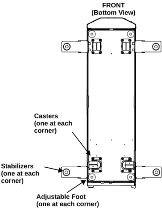
L IEBERT XDH C OMPONENT L OCATIONS AND M ODEL N UMBER N OMENCLATURE
I NTRODUCTION
Pre-Installation Checks
Packing List
Installation Considerations
Room Preparation
G ENERAL PRODUCT INFORMATION
Product/System Description
Checking and Unpacking
- Recyclable Packaging
- Module Handling
- Unpacking the Module
- Taking the Module off the Pallet
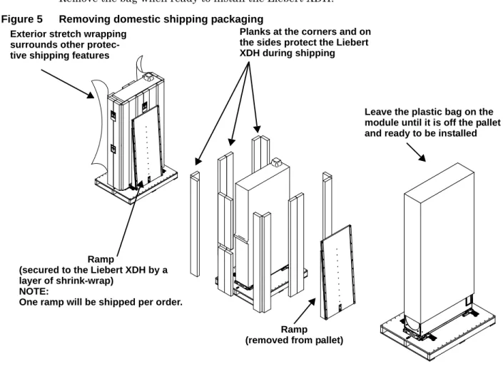
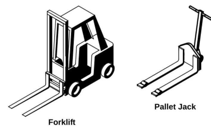
The Liebert XDH is equipped with four wheels in the form of pull-outs, which allow it to be moved to the desired location. Emerson recommends using a forklift or pallet jack to move the Liebert XDH as close to the installation location as possible before removing it from the shipping pallet. Leave the plastic bag on the module until it is off the pallet and ready to install. Boards on the corners and on them. sides protect the Liebert XDH during shipping. attached to the Liebert XDH with a layer of shrink wrap).
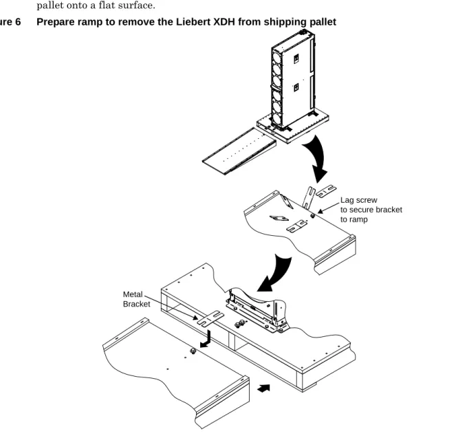
Remove the six hex screws from each of the two mounting brackets, one on each end of the Liebert XDH. At least two properly trained personnel are allowed to roll the Liebert XDH down the ramp and off the pallet onto a flat surface. Make sure the module/carriage is on a level surface before loosening the hardware that secures the Liebert XDH to the shipping pallet.
The Liebert XDH ships with four outrigger-style wheels to allow it to be rolled into position for installation. Emerson recommends using a forklift or pallet jack to move the Liebert XDH as close to its installation location as practical before removing it from the shipping pallet.
M ECHANICAL C ONSIDERATIONS
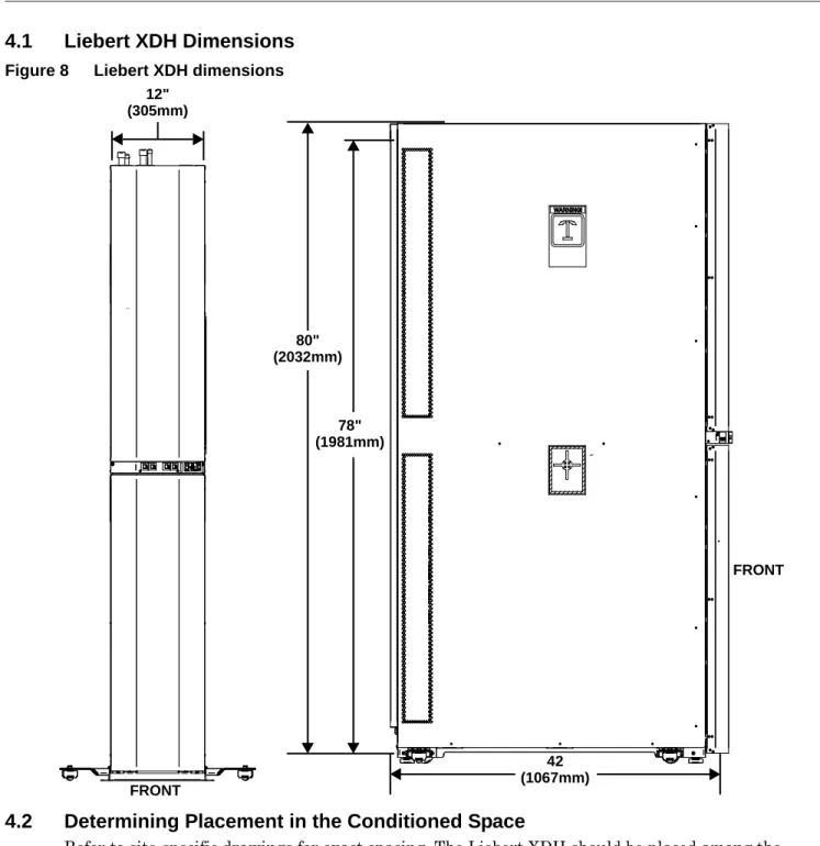
Liebert XDH Dimensions
Determining Placement in the Conditioned Space
I NSTALLING THE M ODULE
Installing the Liebert XDH Within the Enclosure Row
Install a Tie-Down Bracket—Optional
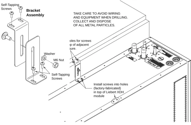
Insert the M6 bolt through the longer slot in the mounting bracket as shown in Figure 10. Place the mounting bracket on top of the Liebert XDH over the factory-drilled holes and over the top of the adjacent enclosure as shown in Figure 10. Mark the locations where two screws self-tapping will connect the connection bracket to the adjacent cabinet.
Taking proper precautions to collect the metal shavings and protect equipment, drill holes in the adjacent cabinet for the two screws.
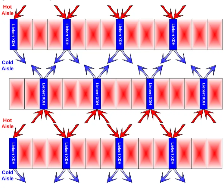
Airflow Direction
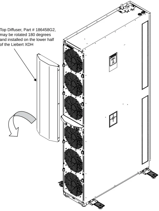
Check the top diffuser fittings and insertion holes on the Liebert XDH to determine how the diffuser should be installed—the diffuser may only be attached to the top half of the Liebert XDH in one way. Rotate the distributor 180 degrees and push it against the lower half of the Liebert XDH until it clicks into the fittings (see Figure 12). Repeat steps 1 through 3 to install the lower diffuser, Part # 186459G2, on the top half of the Liebert XDH.
Top distributor, part # 186458G2, can be rotated 180 degrees and installed on the lower half of the Liebert XDH.
P IPING
European Union Fluorinated Greenhouse Gas Requirements
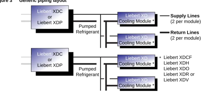
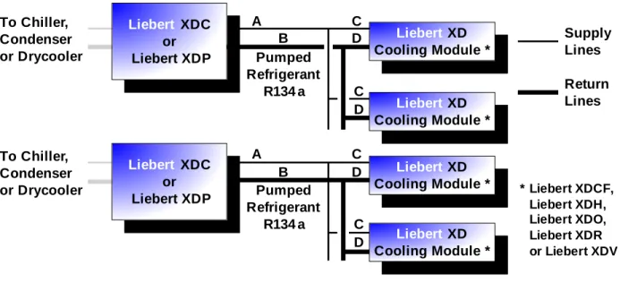
System Connection Configuration
Connection Methods and Points
Insulation
Venting the Holding Charge for Hard-Piped or Removable Liebert XD Flex Pipe
Brazing Preparations
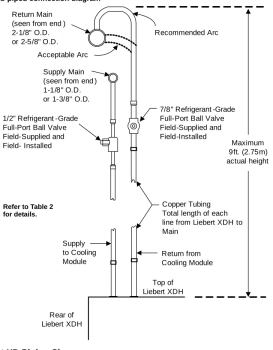
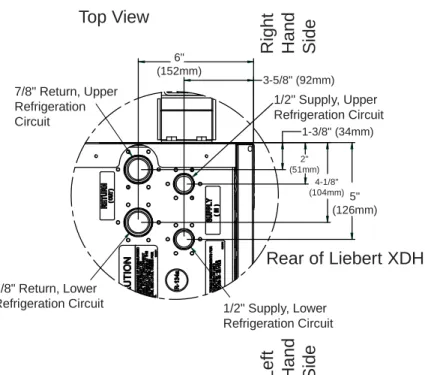
Recommended Piping Size
Hard-Piped Connection Sizes
Liebert XD Piping Slope
Piping Details - Shutoff / Isolation Valves
Refer to the Liebert XDC or Liebert XDP user manual for evacuation, leak control, charging, and start-up procedures. The Liebert XDH modular system with optional flexible piping requires the use of Liebert XD. The prefab pipe is compatible with the Liebert XD Flex Pipe required to attach to the Liebert XDH modules.
Field Installation of Liebert XD Flex Pipe Kit on Liebert XDH
- Connecting Methods—One-Shot Couplings for Pre-Charged Refrigerant Option
- Connect a Liebert XDH with One-Shot Couplings to Liebert XD Flex Pipe
- Connection Methods—Removable Couplings
- Connect Liebert XD Flex Pipe with Removable Coupling to a Liebert XD Cooling
- Connect a Liebert XDH with Liebert XD Flex Pipe to a Liebert XD System
- Disconnect a Liebert XD Flex Pipe from a Liebert XD System
- Disconnecting the Liebert XD Flex Pipe from the Liebert XDH
Do not remove pipe caps or plugs until the module is ready for connection to the Liebert XD Flex Pipe. It is imperative that the brass housing on the Liebert XD Flex Pipe coupling does not rotate while the union nut is being tightened. Tighten the union nut on the Liebert XD Flex Pipe to the coupling on the module with the correct size wrench until you feel a clear resistance, metal-to-metal contact.
Use a marker or pen to draw a line lengthwise across the module coupling to the Liebert XD flexible tube. Tighten the coupling nut on the Liebert XD flex tube to the coupling on the module with an adjustable wrench until you feel a certain amount of resistance. Before connecting the Liebert XDH with the Liebert XD Flex Pipe to the assembly piping, check the entire system for leaks.
Determine the fitting size by locating the number on the Liebert XD Flex Pipe fitting. Thread the union nut of the Liebert XD Flex Pipe fitting onto the port fitting to ensure proper fit of the threads. The Liebert XD Flex Pipe coupling must be held still while the union nut on the coupling is loose.
Piping Figure 31 Profile view of Liebert XD system and Liebert XD Flex pipe location. Recover the coolant in the Liebert XD Flex tubing and module by attaching a coolant recovery device to the Schrader valve. Set the Liebert XD Flex tubing with removable joints aside where it will not be damaged.
E LECTRICAL C ONNECTIONS
Connecting High-Voltage Wiring
Connecting Low-Voltage Wiring—Liebert XDH Smart Modules
CAN BUS L IEBERT XDP O R L IEBERT XDC I NTERCONNECTION W ITH S MART M ODULES
Network Layout Options
Remote Sensor Temperature/Humidity Sensor Placement and Connection
The distance sensors can be placed at the end of a chain or in the middle of a daisy chain as shown. CANbus Liebert XDP Or Liebert XDC Interconnection With Smart Modules Figure 39 Modules on two chains.
CANbus maximum length
CANbus Cables
Connecting CANbus Network
Connection to the Liebert XDP or Liebert XDC
CANbus Liebert XDP or Liebert XDC Interconnection with smart modules Figure 43 Locations P2 and P4 on the CAN isolator.
Connecting to the Liebert XD Smart modules
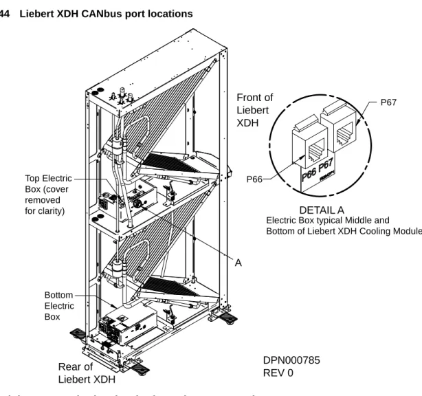
CANbus Liebert XDP or Liebert XDC Interconnect with Smart Modules Figure 44 Liebert XDH CANbus port locations. For Liebert XDHs with both upper and lower circuits connected to the same Liebert XDP or Liebert XDC, the upper and lower control boards must be tied together with a 6.25-foot CANbus cable. The Liebert XD smart modules must only be connected to the Liebert XDP or Liebert XDC to which they are mechanically connected.
For Liebert XDHs with top and bottom circuits tied to different Liebert XDPs or Liebert XDCs, the control cards must be connected in the same way.
CANbus Termination
Remote Temperature and Humidity Sensors Termination
CANbus Liebert XDP or Liebert XDC Interconnection with smart modules Figure 47 Removing the remote sensor cover.
Terminating a Smart Module
Liebert XDP or Liebert XDC CANbus Interconnection with Smart Modules Figure 48 Liebert XD R38 Smart Module Location.
Testing Network Termination
This procedure applies to non-end-of-chain devices, typically the Liebert XD Smart Module. If the resistance is between 110 and 140 ohms and it is not the last control board, the device is not properly terminated. If the resistance is greater than 200 ohms and it is not the last control board, the device is continuous.
I NSTALLATION C HECKLIST AND S YSTEM F ILL FOR S TARTUP
Checklist for Proper Installation
Charging with Refrigerant and Starting the Liebert XD System
O PERATION
Start the Liebert XDH Basic Module
Start the Liebert XDH Smart Module
LED Indicators on Liebert XDH Smart Modules
Activating Remote Shutdown Option
M AINTENANCE
Fluorinated Greenhouse Gas Requirements
Internal Access
Remove the Fan Tray
Accessing Internal Components in the Rear of the Liebert XDH
Open Electric Box—Liebert XDH Basic Modules
Open Electric Box—Liebert XDH Smart Modules
S PECIFICATIONS