Warning:
LOSSNAY
HANDBOOK
MODELS
VL-220CZGV-E VL-220CZGV-EB
Nameplate
April 2016 No. U209
Remote controller (Optional)
PZ-61DR-E PZ-43SMF-E
Filter (Optional)
P-220SHF-E
P-220EMF-E
P-220F-E
Contents
1. Safety precautions ... 3
2. Specifications ... 4
3. Names and functions of components ... 5
4. Outside dimensions ... 6-8
5. Electrical wiring diagram ... 9
6. Circuit board diagrams ...10-11
7. Troubleshooting ... 12-28
8. Before receiving repair requests ... 29
9. Service inspection list ... 29
10. Overhauling procedures ... 30-38
11. Parts catalog ... 39-55
VL-220CZGV-E ... 40-47
VL-220CZGV-EB ... 48-55
Read the following precautions thoroughly before the maintenance, and then inspect and repair the product in a safe manner.
The types and levels of danger that may arise if the product is handled incorrectly are described with the warning symbols shown below.
Warning
Modification is prohibited Do not modify the unit.
(Failure to heed this warning may result in electric shock, fire and/or injury.)
Electric shock
If you must inspect the circuitry while the power is on, do not touch the live parts.
(Failure to heed this warning may result in electric shock.)
Check insulation
Upon completing repair work, always measure the insulation resistance. Verify that it is at least 10 MΩ (with a 500-V DC insulation resistance tester), and then turn on the power.
(Inadequate insulation may result in electric shock.)
Incorrect handling of the product may result in serious injury or death.
Caution
Incorrect handling of the product may result in injury or damage to properties including buildings and equipment.Proper electric work
Use the electric wires designated for electric work, and conduct electric work in accordance with your local "Electric Installation Engineering Standard", the "Indoor Wiring Regulations" and the installation instructions.
(Improper connection or wiring installation may result in electric shock and/or fire.)
Replace damaged and/or degraded parts Be sure to replace the power cord and lead wires if they are damaged and/or degraded.
(Failure to heed this warning may result in electric shock and/or fire.)
Use proper parts and tools
For repair, be sure to use the parts listed in the service parts catalog of the applicable model and use the proper tools.
(Failure to heed this warning may result in electric shock, fire and/or injury.)
Caution against electric shock
Prohibited
Be sure to follow this instruction.
Turn off the power supply
Be sure to shut off the power supply isolator before disassembling the unit for repair.
(Failure to heed this warning may result in electric shock.)
Caution for injury
Do not work at a location where you do not have a sure footing.
(Failure to heed this caution may result in a fall.)
Be sure to follow this instruction.
Wear gloves
Wear gloves when servicing.
(Failure to heed this caution may result in injury to your hands from sharp metal or other edges.)
1. Safety precautions
Be sure to follow this instruction.
Be sure to follow this instruction.
Be sure to follow this instruction.
Be sure to follow this instruction.
Prohibited
2. Specifications
Model name VL-220CZGV-E, VL-220CZGV-EB
Heat exchange system Heat recovery ventilating system
Heat exchanger material Water-resistant paper sensible heat exchanger
Cladding Galvanized steel sheet
Heat insulation material Noncombustibility polyethylene foam
Motor EC motor
Filter Non-woven fabrics filter (Gravitational method 82%, EN779: 2012: G3) Surrounding air condition Shall be between 0°C and 40°C, 80%RH or less
Suction air condition Shall be lower than 40°C, 95%RH Supply fan operation under low outdoor
temperature
0°C to -5°C: Intermittent operation 24 min ON, 6 min OFF -5°C or less: Continuous supply air stopped
Function
Heat recovery ventilation/ Bypass ventilation, Fan speed 1,2,3,4 ( When the optional motorized damper (P-133DUE-E) is used, bypass
ventilation mode can be switched.) Electrical power supply 220-240 V/50 Hz, 220 V/60 Hz
Ventilation mode Heat recovery mode
Fan speed Fan speed 4 Fan speed 3 Fan speed 2 Fan speed 1
Running current (A) 0.60 0.29 0.18 0.11
Input power (W) 80 35 18.5 8.5
Air volume (m3/h) 230 165 120 65
(L/S) 64 46 33 18
External static pressure (Pa) 164 84 44 13
Temperature exchange efficiency (%) 82 84 85 86
Noise (dB) 31 25 19 14
Weight (kg) VL-220CZGV-E: 31, VL-220CZGV-EB: 32
Insulation resistance 10 MΩ or more
Dielectric strength 1000 V AC 1 minute
Model name PZ-61DR-E
Power supply requirement 12 V DC (Supplied from Lossnay unit)
Power consumption 0.3 W
Transmission cable Non polarized 2-wire (0.3 mm2 (AWG22) sheathed cable)
Total wiring length 200 m maximum
Number of controllable Lossnay units 15 Lossnay units maximum (Max. 2 remote controllers installable) Environmental condition Temperature: 0 to 40°C, Humidity: 30% to 90% relative humidity (no
condensation)
Size 120 x 120 x 19 mm
Attention:
• The running current, the input power, the efficiency and the noise are based on the rating air volume, and 230 V/50 Hz.
The noise is measured at 1.5 m under the center of the unit in an anechoic chamber.
• Temperature exchange efficiency (%) is based on winter condition.
• Mitsubishi Electric measures figures in the chart according to Japan Industrial Standard (JIS B 8628), therefore the characteristic curves are measured by chamber method.
3. Names and functions of components
Supply air fi lter fi xing knob Release it to remove the supply air fi lter case.
(3 locations)
Exhaust air fi lter fi xing knob Release it to remove the exhaust air fi lter case.
(2 locations)
Lossnay core Lossnay core exchanges heat between the supply air and the exhaust air.
Supply air fi lter case It holds the supply air fi lter or high effi ciency supply air fi lter.
Exhaust air fi lter case It holds the exhaust air fi lter or medium effi ciency exhaust air fi lter.
Drain pan (supply air side) It holds dew condensation water that occurs inside the Lossnay unit.
Drain outlet It is for discharging dew condensation water that has built up in the drain pan to outside the room.
Supply air fi lter It removes insects, pollen, dirt, dust, and other particles from the outside air that is taken into the room.
Exhaust air fi lter It prevents Lossnay core from clogging.
After the supply air fi lter case is removed
Piping example
• When connecting the RA (return air) to a bathroom, be sure to branch the pipe into two lines and intake return air from two locations, the bathroom and living room (kitchen/dining room).
RA 1
OA
Name of Connection Point Connection Location
RA (Return air)
RA1 For intake from living room, toilet, wash basin, bathroom, etc.
RA2* For optional air duct switching damper (P-133DUE-E)
Exclusive for intake from living room, toilet, wash basin, bathroom, etc.
RA3*
EA
(Exhaust air) For exhaust air of inside air OA
(Outside air) For intake of outside air SA
(Supply air) For air supply opening to living room
* When RA2 and RA3 are used, use grills equipped with fi lter.
Lossnay EA
(exhaust air)
OA (outside air)
SA (supply air)
Bath (Bathroom)
RA1 (return air) Outdoor
side Indoor
side
RA3
RA2
Kitchen / dining room Air duct
switching damper (P-133DUE-E)
(Optional)
4. Outside dimensions
VL-220CZGV-E
Lossnay unit
80
8
174 119 33
8
234
362
ij146 ij124 ij98 31
848 116850
775
20
271229 295
199 86 143
139
885
815 720
151
32031
Drain outlet
Ceiling suspension
Duct connecting
Duct connecting SA
(supply air)
RA1 (return air)
EA (exhaust air)
OA (outside air)
Duct connecting Duct connecting
Drain pan
Working space (required space around Lossnay unit)
720
EA SA
OA RA1
245
86199
320 RA1
OA
234 295
850
Drain outlet Leave at least 100 mm of space
Leave at least 650 mm of space
Leave at least 700 mm of space
Leave at least 900 mm of space
Space required for removing and inserting
Circuit Air duct switching damper
(Optional)
Air duct switching damper
(Optional)
Unit (mm)
VL-220CZGV-EB
80
8
174
20
119 33
8
234
362ij146 ij124 ij98 31
848 116850
775
20
10
271229 295
199 86 143
139
885
815 720
151
32031 20
Ceiling suspension
Duct connecting
Duct connecting SA
(supply air)
RA1 (return air)
EA (exhaust air)
OA (outside air)
Duct connecting Duct connecting
Insulation
Drain pan
720
EA SA
OA RA1
245
86199
32020
RA1 OA
234 295
850
Drain outlet
100 mm of space
650 mm of space
700 mm of space
900 mm of space
Space required for removing and inserting
Circuit Drain outlet
Air duct switching damper (Optional)
Lossnay unit
Working space (required space around Lossnay unit)
Leave at least
Leave at least
Leave at least
Leave at least
Air duct switching damper
(Optional)
Unit (mm)
PZ-61DR-E
Unit (mm) PZ-43SMF-E
Unit (mm) P-220SHF-E, P-220EMF-E, P-220F-E
Model Dimension The number of
filters per set Applicable model
A B C
P-220SHF-E 362 189 15 2
VL-220CZGV-E VL-220CZGV-EB
P-220EMF-E 353 183 15 2
P-220F-E 355 184 15 2
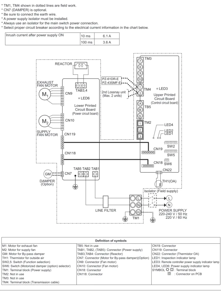
5. Electrical wiring diagram
VL-220CZGV-E, VL-220CZGV-EB
7 8 9 10
S A B 1 2
1 2
N L
N
PE
L
M
1M
2GM CN7
CN118 CN119 CN10 CN9
LED6 TAB3,4
TAB2 TAB5 TAB1
TH1(OA)
TM1
CN19
CN18 CN22
SW5 SW6
SW2 3
TM2 TB5 TM4 TM3
PZ-61DR-E PZ-43SMF-E
LED3
LED4 LED2LED1 REACTOR
2nd Lossnay unit (Max. 2 units) Lower Printed
Circuit Board (Power circuit board)
DAMPER (Option)
Upper Printed Circuit Board (Control circuit board)
Defi nition of symbols M1: Motor for exhaust fan
M2: Motor for supply fan GM: Motor for By-pass damper TH1: Thermistor for outside air SW2,5: Switch (Function selection)
SW6: Switch (Motorized damper (option) selector) TM1: Terminal block (Power supply)
TM2: Not in use
TB5: Not in use
TAB1, TAB2, (TAB5): Connector (Power supply) TAB3,TAB4: Connector (Reactor)
CN7: Connector (Motor for By-pass damper)(Option) CN9: Connector (Fan motor)
CN10: Connector (Fan motor) CN18: Connector
CN118: Connector
CN19: Connector CN119: Connector
CN22: Connector (Thermistor OA) LED1: Inspection indicator lamp
LED3: Remote controller power supply indicator lamp LED4, LED6: Power supply indicator lamp SYMBOL : Terminal block
: Connector on PCB
* TM1, TM4 shown in dotted lines are fi eld work.
* CN7 (DAMPER) is optional.
* Be sure to connect the earth wire.
* A power supply isolator must be installed.
* Always use an isolator for the main switch power connection.
* Select proper circuit breaker according to the electrical current information in the chart below.
Inrush current after power supply ON 10 ms 6.1 A 100 ms 3.6 A
1s digit 10s digit
Fed with power: lit Not fed with power: unlit
Lot number indication Remote controller
power supply indicator (LED3 Green) Bypass monitor output
Pre-heater output (Between 7 and 0)
During bypass mode: 0 ȍ During heat recovery mode: ȍ Malfunction monitor output
(Between 8 and 0)
Error: 0 ȍ Normal: ȍ
Operation monitor output (Between 9 and 0)
When Lossnay is operating: 0 ȍ When Lossnay is stopped: ȍ
Monitor output COM
Remote controller (PZ-61DR-E, etc.) 10 to 13 V DC
External control input
Power circuit board
5 V DC (Insulated)
Power for the circuit
12 to 14 V DC (Insulated)
GND (Insulated)
Fed with power: lit Not fed with power: unlit
SW6
Air duct switching damper selector (Only when the air duct
switching damper (P-133DUE-E) is installed)
SW2 SW5 Function selection
switch Indication of the microcomputer software version
Error indicator (LED1 Green)
Normal: unlit Error: blinking During delay operation: lit
Power supply indicator for the circuit
(LED4 Red) Outdoor air (OA)
thermistor
6. Circuit board diagrams
Circuit board diagram and check points
(1) Control circuit board
(2) Power circuit board
Caution:
The power circuit board is not insulated from the power line (high voltage part), except for the connection part (CN118 and CN119) with the control circuit board. Also, even when the power supply is cut off, the capacitor is charged. Therefore, wait for at least five minutes before starting work.
GND
(Not insulated)
12 to 14 V DC (Insulated) GND (Insulated)
14 to 16 V DC (Not insulated)
Lot number indication Reactor
Supply fan motor (CN10) Pin No. of the connector
1Power for the motor: 280 to 360 V DC 2Not used
3GND
4Power for motor control: 14 to 16 V DC 5Speed command voltage: 0 to 6 V DC 6Rotational speed pulse
Exhaust fan motor (CN9) Pin No. of the connector
1Power for the motor: 280 to 360 V DC 2Not used
3Not used 4GND
5Power for motor control: 14 to 16 V DC 6Speed command voltage: 0 to 6 V DC 7Rotational speed pulse
Fed with power: lit Not fed with power: unlit
Power supply indicator for motor control (LED6 Red)
Control circuit board
Damper motor output Power supply input Fuse Fuse
Applicable Device Applicable Model Lossnay Heat Recovery Ventilator VL-220CZGV-E, VL-220CZGV-EB
Lossnay Remote Controller PZ-61DR-E, PZ-43SMF-E
Air Duct Switching Damper
(Lossnay Heat Recovery Ventilator System Component)
P-133DUE-E
No. Preliminary check item Details
1 Product information • Model name of the product
• Serial number of the product, manufacturing lot number of the circuit board
• Microcomputer software version marked on the circuit board 2 Fault status • Fault status (For example, the fan does not operate.)
• Error code display on the remote controller
• Operation setting of the remote controller (ventilation mode setting, fan speed setting, etc.)
3 Frequency of fault occur- rence
• Frequency of fault occurrence (frequency of date and time of occurrence, regularity of occurrence, etc.)
• Operating time up to fault occurrence
• Date of start of use, date of fault occurrence
4 Timing of fault occurrence • Remote controller operation performed before fault occurrence
• Operating status, etc.
5 System settings • Function selection switch settings of the product
• Model name of the Lossnay remote controller, and whether the air duct switching damper is installed or not
• Function settings on PZ-61DR-E when PZ-61DR-E is used
7. Troubleshooting
Work precautions
• When removing or touching the cables, circuit board or other parts, make sure to turn off the power supply isolator.
• Even after the power supply isolator is turned off, the capacitor on the circuit board retains high voltage for a while. Therefore, before servicing, wait for at least five minutes, and then use a tester to check that the volt- age has dropped.
• Once the power supply is turned off, be sure to wait for at least five minutes before turning the power back on again.
• When servicing, be sure to recreate the malfunction two or three times before starting repairs.
• When servicing, always take care to keep proper footing.
• Before starting the service, always turn off the power supply isolator. Sufficient care must be taken to avoid electric shock or injury.
• Make sure to connect the power supply wires correctly.
• When removing the circuit board, always hold it at both ends and remove carefully so as not to apply force to the surface mounted parts.
• When removing the circuit board, be careful of the metal edges on the board.
• When removing or inserting the connectors for the circuit board, hold the entire housing section. Never pull on the lead wires.
• If it is thought that there is a circuit board malfunction, check for disconnected wires in the print pattern, burnt parts or discoloration.
• If the circuit board is replaced, make sure that the switch settings on the new board are the same as the old board.
The part names in the texts are standardized with the part names in the parts catalog. (There are some exceptions.)
7-1 Service flowchart
After checking the check items below, follow the troubleshooting for servicing.
Note: This device (VL-220CZGV-E, VL-220CZGV-EB) is not compatible with M-NET. When connected to M-NET, a malfunction may occur or an error code may be displayed.
Lossnay does not work after installation is completed.
Lossnay does not work in the trial op- eration after installation is completed, or Lossnay works abnormally during use.
The remote controller does not work after installation is completed.
Operations such as ON/OFF, fan speed or ventilation mode switching are disabled on the remote controller after installation is completed.
Lossnay does not work properly after installation is completed.
• An error code is displayed on the remote controller.
• LEDs on the circuit board blink or light.
7-2 Check Details
(1) Failure mode 1: Lossnay does not work.
Initial Check Items
Check the following details if Lossnay does not work after installation is completed.
1 Power supply
No. Check Item Corrective action
1 Is the main power supply on? Turn the main power supply on.
2 Is the current capacity of the power supply isolator appropriate?
Use an appropriate power supply isolator.
3 Is the designated cable used for the power supply cable?
Use the designated cable.
4 Is the specified power supply supplied to the power supply terminal (TM1)?
220-240 V/50 Hz, 220 V/60 Hz
Supply the designated power supply.
5 Is the power supply cable incorrectly wired, is there a faulty connection or are screws loose?
Connect the cable securely and correctly, and tighten the screws firmly.
6 Is there a faulty connection on the power supply terminals (TM1, TAB1, and TAB2)?
Connect the lead wires securely.
7 Is there a faulty connection on the reactor terminals (TAB3 and TAB4)?
Connect the lead wires securely.
8 Are the power supply indicator lamps (LED4 and LED6, red) lit?
Check the above items.
(1) Failure mode 1: Lossnay does not work, or Lossnay works abnormally.
(2) Failure mode 2: The remote controller does not work.
(3) Failure mode 3: Operations on the remote control- ler are disabled.
(4) Failure mode 4: Lossnay does not work properly.
(5) Failure mode 5: Error code and LED display
Water leaks from the Lossnay unit. (6) Failure mode 6: Water leaks from the Lossnay unit.
No. Check Item Corrective action 1 Are the designated cables used for the remote control-
ler transmission cable? (See Table 2-1.)
Use the designated transmission cables.
2 Are the designated cables used for the external input/
output signal cable? (See Table 2-2.)
Use the designated cables.
3 Are the transmission cables wired using multicore cables?
Use the designated transmission cables.
4 Are multiple transmission cables wired in the same pip- ing duct?
Wire the transmission cable away from one another.
5 Is the power supply cable wired at least 5 cm away from transmission cables?
Wire the power supply cable at least 5 cm away from the transmission cables.
6 Are the transmission cables connected to the desig- nated terminal block? (See Table 2-1.)
Connect the transmission cables to the desig- nated terminal blocks.
7 Are the transmission cables incorrectly wired, is there a faulty connection or are screws loose?
Connect the cable securely and correctly, and tighten the screws firmly.
8 Is the wiring length of the transmission cable within the regulations? (See Table 2-1.)
Wire the cables within the regulations.
9 Does the external input signal match the specifica- tions? (See Table 2-2.)
Input the signal that matches the specifications.
10 Is the external input signal input to the Lossnay set as the main Lossnay?
Input the signal to the Lossnay set as the main Lossnay (SW5-10 ON).
11 Is the function selection for the external output signal set correctly?
Set the function selection switches (SW2-8, 5-2, and 5-6) on the circuit board correctly.
Set the function settings (No. 57 and 58) of PZ- 61DR-E correctly.
Cable PZ-61DR-E or PZ-43SMF-E transmission cable
Type Sheathed cable
Number of cores 2-core cable Cable diameter 0. 3 mm2 (AWG22) Total extension 200 m
Terminal block TM4 12
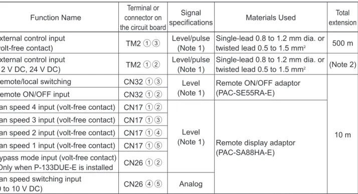
2 Transmission cables (remote controller transmission cable, and external input/output signal cable)
Table 2-1
Remote controller transmission cable specifications
Function Name
Terminal or connector on the circuit board
Signal
specifications Materials Used Total
extension External control input
(volt-free contact) TM2 13 Level/pulse
(Note 1)
Single-lead 0.8 to 1.2 mm dia. or
twisted lead 0.5 to 1.5 mm2 500 m External control input
(12 V DC, 24 V DC) TM2 12 Level/pulse
(Note 1)
Single-lead 0.8 to 1.2 mm dia. or
twisted lead 0.5 to 1.5 mm2 (Note 2)
Remote/local switching CN32 13 Level
(Note 1)
Remote ON/OFF adaptor (PAC-SE55RA-E)
10 m
Remote ON/OFF input CN32 12
Fan speed 4 input (volt-free contact) CN17 12
Level
(Note 1) Remote display adaptor (PAC-SA88HA-E) Fan speed 3 input (volt-free contact) CN17 13
Fan speed 2 input (volt-free contact) CN17 14 Fan speed 1 input (volt-free contact) CN17 15 Bypass mode input (volt-free contact)
*Only when P-133DUE-E is installed CN26 12 Fan speed switching input
(0 to 10 V DC) CN26 45 Analog
Table 2-2 External input/output specifications
<Caution>
• When connecting two Lossnay units and using external input/output, input the signals to the Lossnay (SW5- 10 ON, with the smallest address setting) set as the main Lossnay.
(Note 1) The input signal must conform to the following specifications:
Level signal Volt-free contact, 12 V DC, 24 V DC, the duration of ON and OFF should be 10-second or more.
Pulse signal Volt-free contact, 12 V DC, 24 V DC, the duration of ON should be 200 msec. or more, and minimum 10-second absence is necessary to the next pulse .
In the case of relay contact input, use a relay having a contact rating of 15 V DC/0.1 A or higher and a minimum applicable load of 1 mA or less.
(Note 2) Check the specifications of the external device.
No. Check Item Corrective action
1 Is the main Lossnay set correctly? Check the function selection switch (SW5-10) on the circuit board.
When an external signal is input to two Lossnay units, set one of the units as the main Lossnay (SW5-10 ON).
2 Are the function selection switches on the circuit board set correctly to suit the required application?
Set the function selection switches (SW2 and SW5) on the circuit board correctly.
3 Is the applicable model used as the Lossnay re- mote controller?
Use PZ-61DR-E or PZ-43SMF-E.
(The air conditioner remote controller including PAR-31MAA cannot be used.)
4 When PZ-61DR-E is used, are the function selec- tions set correctly to suit the required application?
Set the function selections correctly.
5 Was a function set with the function selection switches on the circuit board after the function is set with PZ-61DR-E?
Set the function again with PZ-61DR-E.
For the function that can be set with both PZ- 61DR-E and the function selection switches, if the function is set to other than "DIP-SW priority" with PZ-61DR-E, setting with the function selection switches is disabled.
4 Function setting (See the Lossnay technical manual for details.)
Terminal block TM3 90 TM3 80 TM3 70
Function Name Operation monitor
After-heater Malfunction monitor Bypass monitor
Signal specifications Volt-free contact
Output rating 240 V AC, 1 A
24 V DC, 1 A
Min. applicable load 220 V AC, 100 mA
5 V DC, 100 mA Table 3-1 Monitor Output Specifications
No. Check Item Corrective action
1 Is the signal cable wired by multicore cable? Wire the cable using a 2-core cable.
2 Are the signal cables and transmission cables wired in the same piping duct?
Wire the signal cables away from the transmission cables.
3 Is the power supply cable wired at least 5 cm away from signal cables?
Wire the power supply cable at least 5 cm away from the signal cables.
4 Is the signal cable connected to the designated terminal block? (See Table 3-1.)
Connect the signal cable to the designated terminal block.
5 Is the signal cable incorrectly wired, is there a faulty connection or are screws loose?
Connect the cable securely and correctly, and tighten the screws firmly.
6 Is the output capacity of the signal cable within rat- ing? (See Table 3-1.)
Use the signal cable within rating.
7 Is the function selection for the external output signal set correctly?
Set the function selection switches (SW2-8, 5-2, and 5-6) on the circuit board correctly.
Set the function settings (No. 57 and 58) of PZ- 61DR-E correctly.
(See the Lossnay technical manual.) 3 Monitor output signal cable
No. LED Contents Check Item Corrective action 1 LED1
(green)
Lossnay main unit error indicator
Blinking: Starting up, or error oc- curred
See Failure Mode 5.
Lit: During delay operation Lossnay operates after the delay time has passed.
Unlit: Other than above It is normal.
2 LED2 (red)
M-NET System error indicator
Unlit It is normal.
3 LED3 (green)
Remote control- ler power supply indicator
Lit: Power supplied to the remote controller (Main Lossnay)
The LED goes out when power is sup- plied to the remote controller from an- other Lossnay unit in the case of using two Lossnay units.
Unlit: Power not supplied to the remote controller (Sub Lossnay) 4 LED4
(red)
Power supply indicator (control circuit board)
Check that this LED is lit The LED lights while power is being supplied to the control circuit board.
5 LED6 (red)
Power supply indicator (power circuit board)
Check that this LED is lit The LED lights while power is being supplied to the power circuit board.
(Do not touch components on the circuit board when the LED is lit.)
5 LED Indications on the circuit board
No. Problem Factor Corrective action 1 The fan does not
operate even though the trial operation switch (SW2-1) on the cir- cuit board is turned ON.
The connectors between the fan motor and circuit board is discon- nected.
Check the connector (CN9) for the exhaust fan motor and the connector (CN10) for the supply fan motor.
The connector between the con- trol circuit board and power circuit board is disconnected.
Check the connector connections (CN18-CN118 and CN19-CN119).
The temperature around the prod- uct is high.
Use the product at a temperature of 40°C or lower.
Fan motor failure Check the resistance between the motor leads.
(See chapter 7. (8) Motor resistance table (page 28).) If the measured value is significantly different from the values specified in the table, replace the fan motor.
Circuit board failure Disconnect the connectors (CN9 and CN10), and check the output voltage of each pin of the connectors within one minute after turning the switch (SW2-1) ON. (One minute later, the error will occur.)
(See chapter 6. (2) Power circuit board (page 11).) If the voltage value is abnormal, replace the circuit board.
If the problem persists, replace the fan motor.
2 Though the remote controller display indicates the fan is running, the fan stops by itself.
The Lossnay unit is operating in the protective mode (intermittent operation).
When PZ-61DR-E is used, it displays the icon
" " that indicates the protective operation is in- progress. For details, see the remote controller manual.
The Lossnay unit is set to the delay operation.
When PZ-61DR-E is used, it displays the icon
" " that indicates the delay operation is in- progress.
LED1 (green) on the control circuit board lights.
Lossnay operates in 30 minutes (or 15 minutes) after the external signal is input to run.
Check the function selection switch (SW5-1) on the circuit board or the function setting (No. 9) of PZ-61DR-E. (See the Lossnay technical manual.) The temperature around the prod-
uct is high.
When the ambient temperature of the product is high (higher than 40°C), the fan may stop to prevent the fan motor from overheating.
3 The fan does not stop even though the remote control- ler is operated to stop operation.
The after-heater is set to be used. If the after-heater is set to be used, the fan con- tinues operating for three minutes after the stop operation.
Check the function selection switches (SW2-8 and 5-2) on the circuit board or the function set- tings (No. 57 and 58) of PZ-61DR-E. (See the Lossnay technical manual.)
Individual function check items
If Lossnay does not work in the trial operation after installation is completed, or if Lossnay works abnormally during use, check the following items.
No. Problem Factor Corrective action 4 Even though the
remote controller is operated to change the fan speed, the fan speed does not change.
The indoor negative pressure setting or the indoor positive pres- sure setting is set.
Check the function selection switches (SW2- 4 and 2-5) on the circuit board or the function settings (No. 6 and 7) of PZ-61DR-E. (See the Lossnay installation manual.)
The external fan speed input is set. (CN17)
When PZ-61DR-E is used, it displays the icon " ".
Check the fan speed switching input (CN17).
The external fan speed input is set. (CN26)
When PZ-61DR-E is used, it displays the icon " ".
Check the function selection switches (SW2-3 and 2-6) on the circuit board or the function set- ting (No. 63) of PZ-61DR-E. (See the Lossnay technical manual.)
The system is operating in the protective mode (intermittent operation).
When PZ-61DR-E is used, it displays the icon
" " that indicates the protective operation is in-progress.
For details, see the remote controller manual.
5 The fan operation is unstable.
The motor rotation speed is under control.
This product controls the motor by detecting the motor rotation speed. The fan operation may be unstable during rotation speed control (for maxi- mum about 10 minutes).
6 The damper does not operate even though the trial operation switch (SW2-1) on the cir- cuit board is turned ON.
* Only when the air duct switch- ing damper (P-133DUE-E) is installed.
The connector between the geared motor and circuit board is disconnected.
Check the connection of the connector (CN7) on the power circuit board.
The air duct switching damper selector (SW6) is not set correctly.
Turn off the switch (SW6-1).
When operating two Lossnay units, turn off the switch (SW6-1) of both Lossnay units.
Geared motor failure of the air duct switching damper
Turn the trial operation switch (SW2-1) ON.
The geared motor operates in about several seconds.
If the geared motor does not operate, replace the geared motor. (For details about the air duct switching damper, see the handbook for P-133DUE-E.)
Circuit board failure of the Lossnay unit
Disconnect the connector (CN7) from the power circuit board and check the voltage value be- tween the pins of CN7 when the trial operation switch (SW2-1) is turned ON.
(Voltage is output in about several seconds after switch ON.)
If there is no voltage value, replace the circuit board.
If the problem persists, replace the geared mo- tor of the air duct switching damper. (See the handbook for P-133DUE-E.)
7 Even though the remote controller is operated to change the ventilation mode, the ventilation mode is not changed.
The outdoor temperature is 8°C or lower.
When the outdoor temperature is 8°C or lower, the ventilation mode is fixed to the Heat recov- ery mode.
No. Problem Factor Corrective action 8 The ventilation
mode cannot be switched when Lossnay is operat- ing in the automatic mode.
* Only when the air duct switch- ing damper (P-133DUE-E) is installed.
Temperature condition for Heat recovery mode or Bypass mode is not satisfied.
Check the temperature map.
For details, see the Lossnay installation manual.
Temperature condition is not set correctly.
Set the lower limit to temperatures lower than that of the upper limit.
It has not passed 30 minutes since the ventilation mode is switched.
Switching of the ventilation mode is controlled in 30 minutes cycle.
The outdoor temperature is 8°C or lower.
When the outdoor temperature is 8°C or lower, the ventilation mode is fixed to the Heat recov- ery mode.
The signal is input to the Bypass mode switching input (CN26 12).
Check the Bypass mode switching input (CN26 12). (See the Lossnay technical manual.) 9 The Lossnay unit
generates abnormal sounds or vibra- tions.
Fan operation failure Set the supply/exhaust fan power up setting.
(See the Lossnay installation manual.) The filters (filter assemblies) are
not securely installed.
Check that the filters (filter assemblies) are securely installed.
Filters are clogged. Clean the filters.
The Lossnay unit is not securely installed.
Check that the Lossnay unit is securely in- stalled.
The ceiling suspension fixtures (hangers) or anchor bolts are loosened.
Retighten the ceiling suspension fixtures (hang- ers) or anchor bolts.
The ducts are not securely con- nected.
Check that the ducts are securely connected.
Foreign matter is stuck to the centrifugal fans.
Remove the foreign matter.
It may lose the balance of the centrifugal fan.
The Lossnay unit generates sounds at the time of the ventila- tion mode switching.
* Only when the air duct switch- ing damper (P-133DUE-E) is installed.
When ventilation mode has been changed, the air duct switching damper makes operating sounds. It is normal.
10 Air volume is too
small. Is the air filter clogged? Clean the air filter.
Pressure loss in the duct is too high.
Set the supply/exhaust fan power up setting.
(See the Lossnay technical manual.) The air duct switching damper
selector (SW6) is not set correctly after the circuit board is replaced.
Make the switch (SW6) setting appropriate for the model.
SW6-1 SW6-2 SW6-3 SW6-4
Without the damper ON ON ON ON
With the damper OFF ON ON ON
The indoor negative pressure setting or the indoor positive pres- sure setting is set.
Check the function selection switches (SW2- 4 and 2-5) on the circuit board or the function settings (No. 6 and 7) of PZ-61DR-E. (See the Lossnay technical manual.)
Power supply voltage is low. Check the power supply voltage.
No. Problem Factor Corrective action 1 Nothing is displayed
on the remote con- troller.
The ON/OFF lamp does not blink.
The power of the Lossnay unit is not ON.
Check the items described in (1) 1.
Faulty connection of the remote controller transmission cable
Check the items described in (1) 2.
Three or more Lossnay units are connected.
Only up to two Lossnay units can be connected.
The wiring length of the remote controller exceeds 200 m.
The wiring length of the remote controller shall be within 200 m.
When connecting with two Lossnay units, both Lossnay units are set as the main Lossnay (SW5-10 ON).
Only one Lossnay unit can be set as the main Lossnay.
2 The remote control- ler continues to dis- play "Please Wait".
Error code "6831" is displayed.
The remote controller is starting up.
The remote controller displays "Please Wait"
during start-up for maximum four minutes.
Faulty connection of the remote controller transmission cable
Check the items described in (1) 2.
PZ-43SMF-E is used together. PZ-61DR-E and PZ-43SMF-E cannot be used together.
3 It takes time for the remote controller to be fed with power after turning the Lossnay unit ON.
The Lossnay unit is starting up. The remote controller is not fed with power dur- ing start-up of the Lossnay unit for maximum one minute.
(2) Failure mode 2: The remote controller does not work.
If the remote controller does not work after installation is completed, check the following items.
1 PZ-61DR-E
2 PZ-43SMF-E
No. Problem Factor Corrective action
1 The power indicator
" " is not displayed.
The power of the Lossnay unit is not ON.
Check the items described in (1) 1.
Faulty connection of the remote controller transmission cable
Check the items described in (1) 2.
Three or more Lossnay units are connected.
Only up to two Lossnay units can be connected.
The wiring length of the remote controller exceeds 200 m.
The wiring length of the remote controller shall be within 200 m.
When connecting with two Lossnay units, both Lossnay units are set as the main Lossnay (SW5-10 ON).
Only one Lossnay unit can be set as the main Lossnay.
2 "H0" is displayed on the remote controller.
The remote controller is starting up.
The remote controller displays "H0" during start- up for a maximum of one minute.
3 It takes time for the remote controller to be fed with power
The Lossnay unit is starting up. The remote controller is not fed with power dur- ing start-up of the Lossnay unit for a maximum of one minute.
No. Check item Notes 1 Are the function selection switches
(SW2 and SW5) on the Lossnay circuit board set correctly to suit the required application?
Depending on the settings of the function selection switches, Lossnay may automatically operate or stop, or specific operation may be unable to be performed with the remote controller.
2 When PZ-61DR-E is used, are the function selections set correctly to suit the required application?
Depending on the settings of the function selections, Lossnay may automatically operate or stop, or specific operation may be unable to be performed with the remote controller.
3 When PZ-61DR-E is used, are icons and characters displayed on the PZ- 61DR-E screen?
Based on the icon and characters, you can check statuses such as the timer operation and protective operation.
(See the Lossnay installation manual or remote controller manual.) 4 Is the external input used? If the interlock mode is set to the "External input priority ON/OFF
interlock" and if the external device is operating, the stop operation by PZ-61DR-E is prohibited. (See the Lossnay technical manual.) If the Remote/Local switching (CN32) is set to remote, the start/
stop operation by the Lossnay remote controller is prohibited.
(See the Lossnay technical manual.)
Priority is given to the operation by the fan speed switching in- put (CN17) and Bypass mode switching input (CN26, only when P-133DUE-E is installed).
(See the Lossnay technical manual.)
(3) Failure mode 3: Operations on the remote controller are disabled.
Initial Check Items
If the system cannot be operated with the remote controller after installation is completed, check the following items.
Individual check items
If the system cannot be started/stopped using the remote controller after installation is completed, check the following items.
1 PZ-61DR-E
No. Problem Factor Corrective action
1 When connecting with two Lossnay units, either one or both of Lossnay units do not operate.
The power of the Lossnay unit is not ON.
Check the items described in (1) 1.
Faulty connection of the remote controller transmission cable
Check the items described in (1) 2.
The remote controller transmis- sion cables are not correctly connected between the terminals (TM4 12) of the Lossnay units.
Connect the remote controller transmission cables correctly between the terminals (TM4 12) of the Lossnay units.
The system is operating in the protective mode (intermittent operation).
For details, see the Lossnay technical manual.
2 The screen display of the remote con- troller changes by itself. Even if you press the buttons, the screen returns to the original screen right away.
Faulty connection of the remote controller transmission cable
Check the items described in (1) 2.
3 The outdoor tem- perature display of PZ-61DR-E blink.
The outdoor temperature is out- side the measurement range.
In the following cases, the temperature display blinks.
Outdoor temperature:
2 Interlocking with external devices
No. Problem Factor Corrective action
1 Lossnay interlock settings cannot be performed with the remote controller.
The power of the Lossnay unit is not ON.
Check the items described in (1) 1.
Faulty connection of the remote controller transmission cable
Check the items described in (1) 2.
2 Lossnay does not perform interlock operation.
The power of the Lossnay unit is not ON.
Check the items described in (1) 1.
Faulty connection of the remote controller transmission cable or external input/output signal cables
Check the items described in (1) 2.
The Lossnay unit is not set for interlock operation.
Set the interlock setting.
The terminal block connected and the type of external signal do not match (charged or volt-free)
Check the type of external signal and the con- nections of the external control input terminal (TM2).
The type of external signal and input setting do not match (level signal or pulse signal).
Check the type of external signal and the setting of the input (level or pulse).
(See the Lossnay technical manual.) The Lossnay unit is set to the
delay operation.
When PZ-61DR-E is used, it displays the icon
" " that indicates the delay operation is in- progress.
LED1 (green) on the control circuit board lights.
The Lossnay unit starts operation in 30 minutes (or 15 minutes) after starting operation by the external signal.
Check the function selection switch (SW5-1) on the circuit board or the function setting (No. 9) of PZ-61DR-E. (See the Lossnay technical manual.) The interlock mode of the Lossnay
unit is set to "ON Interlock" or
"OFF Interlock".
Check the interlock mode setting.
(See the Lossnay technical manual.) When using two Lossnay units,
no Lossnay unit is set to the main Lossnay.
When using two Lossnay units, set one Lossnay unit as the main Lossnay (SW5-10 ON) to input external control signal.
(See the Lossnay technical manual.) When using two Lossnay units,
external control signal is input to a Lossnay unit other than the main Lossnay.
The Lossnay unit is operating in the protective mode (intermittent operation).
For details, see the Lossnay technical manual.
No. Problem Factor Corrective action 1 Actual fan speed
of the Lossnay unit differs from the fan speed set with the remote controller.
The signal is input to the fan speed input (CN17).
Check the fan speed input (CN17).
(See the Lossnay technical manual.) The signal is input to the fan speed
switching input (CN26 45).
Check the fan speed switching input (CN26 45). (See the Lossnay technical manual.) Function setting (No. 8) of PZ-
61DR-E "Max. fan speed setting during the first 30 minutes" is enabled.
Lossnay operates at fan speed 4 for 30 minutes when operation starts.
(See the Lossnay technical manual.) The indoor negative pressure
setting or the indoor positive pres- sure setting is set.
Check the function selection switches (SW2-4 and 2-5) on the circuit board or the function set- tings (No. 6 and 7) of PZ-61DR-E.
(See the Lossnay installation manual.) The system is operating in the
protective mode (intermittent operation).
When PZ-61DR-E is used, it displays the icon
" " that indicates the protective operation is in-progress.
For details, see the remote controller manual.
2 Even though the remote controller is operated to change the ventilation mode, the ventila- tion mode is not changed.
The outdoor temperature is 8°C or lower.
When the outdoor temperature is 8°C or lower, the ventilation mode is fixed to the Heat recov- ery mode.
The signal is input to the Bypass mode switching input (CN26 12).
Check the Bypass mode switching input (CN26 12). (See the Lossnay technical manual.) Individual check items
If Lossnay does not work after installation is completed, check the following items.
(4) Failure mode 4: Lossnay does not work properly.
Initial Check Items
If Lossnay does not work properly after installation is completed, check the following items.
No. Check item Notes
1 Are the function selection switches (SW2 and SW5) on the Lossnay circuit board set correctly to suit the required application?
Depending on the settings of the function selection switches, Lossnay may automatically operate or stop, or specific operation may be unable to be performed with the remote controller.
2 When PZ-61DR-E is used, are the function selections set correctly to suit the required application?
Depending on the settings of the function selections, Lossnay may automatically operate or stop, or specific operation may be unable to be performed with the remote controller.
3 When PZ-61DR-E is used, are icons and characters displayed on the PZ- 61DR-E screen?
Based on the icon and characters, you can check statuses such as the timer operation and protective operation.
(See the Lossnay installation manual or remote controller manual.) 4 Is the external input used? If the interlock mode is set to the "External input priority ON/OFF
interlock" and if the external device is operating, the stop operation by PZ-61DR-E is prohibited. (See the Lossnay technical manual.) If the Remote/Local switching (CN32) is set to remote, the start/
stop operation by the Lossnay remote controller is prohibited.
(See the Lossnay technical manual.)
Priority is given to the operation by the fan speed switching in- put (CN17) and Bypass mode switching input (CN26, only when P-133DUE-E is installed).
(See the Lossnay technical manual.)
Error Code
LED1
(green) Symptom Cause Corrective action
0900 Trial opera- tion
The trial operation switch (SW2-1) on the circuit board is set to "ON".
Check the trial operation switch.
(See the Lossnay installation manual.) 4101 11
blinks
Overcurrent error of the remote controller terminal
Shorting between remote controller terminals
Check the remote controller wiring.
Two Lossnay units are set as the main Lossnay (SW5-10 ON).
Only one Lossnay unit can be set as the main Lossnay.
(See the Lossnay technical manual.) Circuit board failure Replace the circuit board.
Remote controller failure Replace the remote controller.
4116 1 blink
Abnormal rotation of the supply fan motor (Centrifugal fan does not work, insuf- ficient motor speed, ex- cessive mo- tor speed, or rotation de- tected when operation is stopped)
Faulty connection of the supply fan motor connector (CN10) on the power circuit board
Check the connector (CN10) connection.
Faulty connection of the connectors (CN18 - CN118 and CN19 - CN119) between the control circuit board and power circuit board
Check the connector connections (CN18 - CN118 and CN19 - CN119).
The temperature around the product is high.
Use the product at a temperature of 40°C or lower.
The motor and centrifugal fan are not fixed securely.
Check the installation state of the motor and centrifugal fan, and fix them securely.
Deformed centrifugal fan Replace the centrifugal fan.
Foreign objects around the centrifu- gal fan
Check the air course and around the cen- trifugal fan, and remove any foreign matter.
Fan motor failure Replace the fan motor.
Circuit board failure Replace the circuit board.
2 blinks
Abnormal rotation of the exhaust fan motor (Centrifugal fan does not work, insuf- ficient motor speed, ex- cessive mo- tor speed, or rotation de-
Faulty connection of the exhaust fan motor connector (CN9) on the power circuit board
Check the connector (CN9) connection.
Faulty connection of the connectors (CN18 - CN118 and CN19 - CN119) between the control circuit board and power circuit board
Check the connector connections (CN18 - CN118 and CN19 - CN119).
The temperature around the product is high.
Use the product at a temperature of 40°C or lower.
The motor and centrifugal fan are not fixed securely.
Check the installation state of the motor and centrifugal fan, and fix them securely.
7 s
Error display example: Two blinks 0.25 s 0.25 s 0.25 s
ON OFF
(5) Failure mode 5: Error code and LED display
An error code displayed on the remote controller (PZ-61DR-E or PZ-43SMF-E) and blinking or illumination of LED1 (green) on the circuit board show the type of an error.
The LED blink interval is 0.25 seconds for both on and off. The display duration is approximately 7 seconds.
Error display list
Error Code
LED1
(green) Symptom Cause Corrective action
5101 4 blinks
Outdoor air (OA) ther- mistor re- lated error
Faulty connection of the thermis- tor connector (CN22) on the control circuit board
Check the connector (CN22) connection.
Thermistor failure Disconnect the connector (CN22), and check the resistance of the thermistor.
If the equivalent thermistor resistance differs greatly from the ambient tem- peratures, replace the thermistor. (See (7) Temperatures and thermistor resistance table (page 28).)
6801 9 blinks
PZ-43SMF-E communica- tion error
Multiple PZ-43SMF-E transmission cables are wired using multicore cables.
Using the applicable cable, wire the trans- mission cable away from one another.
The power supply cable is too close to the PZ-43SMF-E transmission cable.
Wire the power supply cable at least 5 cm away from the transmission cable.
Faulty connection of the PZ- 43SMF-E transmission cable
Check the transmission cable connections.
The wiring length of the PZ-43SMF-E transmission cable is longer than specified (200 m or more).
Check the wiring length of the transmission cable.
6831 9 blinks
PZ-61DR-E communica- tion error (no reception)
Faulty connection of the PZ-61DR-E transmission cable
Check the items described in (1) 2.
If the error re-occurs, check for noise on the transmission cable.
If the above does not correct the problem, replace the Lossnay circuit board or PZ- 61DR-E remote controller.
6832 9 blinks
PZ-61DR-E communica- tion error (synchroni- zation recov- ery error)
Faulty connection of the PZ-61DR-E transmission cable
Check the items described in (1) 2.
If the error re-occurs, check for noise on the transmission cable.
If the above does not correct the problem, replace the Lossnay circuit board or PZ- 61DR-E remote controller.
6833 9 blinks
PZ-61DR-E communica- tion error (hardware error)
Faulty connection of the PZ-61DR-E transmission cable
Check the items described in (1) 2.
If the error re-occurs, check for noise on the transmission cable.
If the above does not correct the problem, replace the Lossnay circuit board or PZ- 61DR-E remote controller.
6834 9 blinks
PZ-61DR-E communica- tion error (start bit detection error)
Faulty connection of the PZ-61DR-E transmission cable
Check the items described in (1) 2.
If the error re-occurs, check for noise on the transmission cable.
If the above does not correct the problem, replace the Lossnay circuit board or PZ- 61DR-E remote controller.
7113 10 blinks
Function set- ting error
Two Lossnay units are set as the main Lossnay (SW5-10 ON).
Only one Lossnay unit can be set as the main Lossnay.
(See the Lossnay technical manual.) The air duct switching damper selec-
tor (SW6) is not set correctly.
Make the switch (SW6) setting appropriate for the model.
SW6-1 SW6-2 SW6-3 SW6-4
(6) Failure mode 6: Water leaks from the Lossnay unit.
No. Problem Factor Corrective action
1 Water leaks from the Lossnay unit.
Is the drain pipe tilted downward at an angle of 1° or more?
Tilt the drain pipe at an angle of 1° or more.
Is the drain hose securely con- nected?
Connect the drain hose securely.
Is the drain pan clogged with dust?
Remove dust.
Is the drain pipe insulated for prevention from freezing?
Insulate the drain pipe securely.
Is the Lossnay unit installed at the angle as shown below?
0 to 1°
Drain outlet direction
OA
RA1 Drain outlet Duct connecting flange direction Tilt 0 to 1° towards drain discharge side
Horizontal (within ±1°)
Install the Lossnay unit as shown in the left diagram.
Does dew condense on the exte- rior surface?
• Check that the Lossnay unit and duct pipe are installed on the interior side of the insulating layer in the attic.
• Check that the duct and drain pipes are insu- lated.
2 Water leaks from the duct pipe.
Is each duct pipe tilted toward the outside for 1/30 or more?
Tilt each duct pipe for 1/30 or more.
Is the duct connecting flange insu- lated up to the base?
Follow the installation manual and insulate the duct connecting flange securely.
Is the duct securely connected to the Lossnay unit and duct con- necting flange?
Connect the duct securely.
*For details of drain and duct pipes, see the installation manual.
Temperature (°C)
Resistance value (kΩ)
Temperature (°C)
Resistance value (kΩ)
Temperature (°C)
Resistance value (kΩ)
Temperature (°C)
Resistance value (kΩ)
Temperature (°C)
Resistance value (kΩ)
-30 53.9 to ∞ -7 18.0 8 9.5 23 5.4 38 3.1
… …
-6 17.2 9 9.2 24 5.1 39 3.1
-20 32.8 -5 16.5 10 8.8 25 5.0 40 3.0
-19 31.2 -4 15.7 11 8.5 26 4.8 41 2.8
-18 29.8 -3 15.1 12 8.1 27 4.7 42 2.7
-17 28.4 -2 14.5 13 7.8 28 4.5 43 2.7
-16 27.1 -1 13.8 14 7.6 29 4.3 44 2.6
-15 25.8 0 13.3 15 7.3 30 4.2 45 2.5
-14 24.7 1 12.8 16 7.0 31 4.0 46 2.4
-13 23.6 2 12.2 17 6.7 32 3.9 47 2.3
-12 22.5 3 11.7 18 6.5 33 3.7 48 2.2
-11 21.5 4 11.2 19 6.3 34 3.6 49 2.2
-10 20.6 5 10.7 20 6.0 35 3.5 50 2.1
-9 19.7 6 10.3 21 5.8 36 3.4 … …
-8 18.8 7 10.0 22 5.6 37 3.2 90 0 to 0.7
(7) Temperatures and thermistor resistance table
* Measure the outdoor air (OA) thermistor resistance across pin No. 1 and 2 of CN22.
(8) Motor resistance table
Cautions:
• Before disconnecting the motor connectors, make sure that the power is turned OFF and the circuit board is discharged adequately.
• Even after the power supply is cut off, the capacitor is charged. Therefore, high voltage is applied to the mo- tor for a while. Make sure that the LEDs on the circuit board are turned OFF before starting work.
• Never touch the circuit board while the power is ON. It causes electric shock and failure of the unit.
Replace the fan motor in the following cases.
1 If it is hard to rotate the motor shaft by hand
2 If the resistance between the motor leads is significantly different from the values specified in the table below *Before measuring the resistance, the motor connectors must be disconnected from the circuit board.
Lead color Black-Red Black-White Black-Yellow Black-Brown
Normal resistance About 440 MΩ About 40 kΩ About 90 kΩ ∞
8. Before receiving repair requests
Frequently asked question Response
Lossnay does not operate. 1 If the breaker on the distribution board is turned off, turn it on.
2 If the ON/OFF button on the remote controller is set to OFF, set it to ON. It takes one to four minutes for the remote controller to be fed with power after turning the Lossnay unit ON.
Operating noise has in- creased.
1 If the filters are not securely installed, re-install them.
2 If the filters are clogged, clean them.
3 When the outdoor hood is blocked, remove the obstacle.
The air volume is low. If the filters are clogged, clean them.
Bubbling sound is heard from the Lossnay unit.
Dew condensation water in the drain pipe is sometimes sucked into wind pres- sure of the Lossnay unit and may not be easily discharged.
Operate Lossnay at the low fan speed, and dew condensation water in the drain pipe will be easily discharged and the sound will stop.
Dew condensation water is pooled in the filter case.
Dew condensation water may be pooled depending on the use environment.
It is normal.
The loudness of the opera- tion sound differs in each room.
The loudness of the sound may be different depending on the pipe length in each room. It is normal.
The wind sometimes stops. The system is operating in the protective mode (intermittent operation).
It is normal. (See the Lossnay instruction manual.)
The air supply wind is cold. The air supply wind becomes cold depending on the outside air condition.
It is normal.
The ventilation mode can- not be switched.
* Only when the air duct switching damper (P-133DUE-E) is installed.
When the outdoor temperature is 8°C or lower, the ventilation mode is fixed to the Heat recovery mode.
Location Inspection Check Result
Electric wiring
Is the power supply wire connected to the terminal block securely?
Is the wiring correct?
Product
Is the main unit mounted securely?
Is the earth cable installed?
Does the product operate as described in the instruction manual when operat- ing the remote controller?
Are the air supply fan and air exhaust fan operating?
Does the product operate without abnormal vibrations or noise?
9. Service inspection list
10. Overhauling procedures
Work precautions
• Before replacing parts, repair troubled sections according to the instructions described in the troubleshooting.
• When servicing, always keep proper footing.
• When servicing, always turn off the power supply isolator. Pay sufficient attention to avoid electrical shock or injury. Even after the power supply isolator is turned off, the capacitor on the circuit board retains high volt- age for a while. Therefore, before servicing, wait for at least five minutes, and then use a tester to check that the voltage has dropped.
• Once the power supply is turned off, be sure to wait for at least five minutes before turning the power back on again.
• When removing the circuit board, always hold it at both ends and remove carefully so as not to apply force to the surface mounted parts.
• When removing the circuit board, be careful of the metal edges on the board.
• When removing or inserting the connectors for the circuit board, hold the entire housing section. Never pull on the lead wires.
• If it is thought that there is a circuit board malfunction, check for disconnected wires in the print pattern, burnt parts or discoloration.
• If the circuit board is replaced, make sure that the switch settings on the new board are the same as the old board.
• Always connect the power wire properly.
• After completing repairs, check that the unit operates properly.
• Always wear gloves when servicing.
The part names in the texts are standardized with the part names in the parts catalog. (There are some exceptions.)
<Internal view and major components>
Filter assembly (RA)
Filter assembly (OA)
Thermistor
Lossnay core Control unit
SA fan assembly
EA fan assembly
Drain pan
Bottom casing EA: Exhaust air
SA: Supply air
RA: Return air OA: Outside air