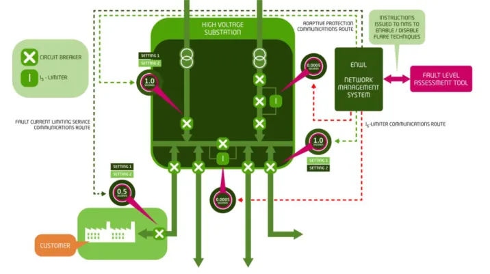
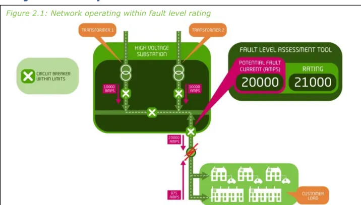
When the potential fault current exceeds the existing switchgear rating, the Fault Level Assessment Tool provides a. The Fault Level Assessment Tool is implemented in the preparation phase, ready for the two-year evaluation phase.
Low Carbon Networks Fund Full Submission Pro-forma
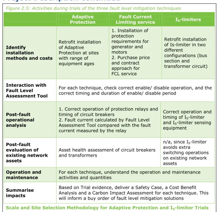
Project Description continued
Changes since Initial Screening Process (ISP)
The scope of the FLARE project has not changed since the submission of the Initial Screening Proforma.
Project Business Case
Project Business Case continued
Evaluation Criteria
The Carbon Plan2, published by the UK Government in 2011, outlines the importance of the transition to a low carbon economy and sets out how legally binding targets to reduce greenhouse gas emissions will be achieved. The Greater Manchester Combined Authority (GMCA), one of our Project supporters, is one such organization with challenging carbon goals, including local, low-carbon production and a future vision of district heating networks.
Evaluation Criteria continued
Knowledge dissemination
FLARE will deliver a toolkit that enables a GB DNO network designer to choose which FLARE or FlexDGrid fault level mitigation technique to apply in different situations. A knowledge dissemination roadmap will be refined at the start of FLARE project delivery to create a clear and effective dissemination plan.
Knowledge dissemination continued
Project Readiness
Assessment of the FlexDGrid project and international assessment of FLARE concepts As part of the development of the bid material for the FLARE project, PB Power was contracted to evaluate the technical feasibility of the FLARE concepts and the use of these techniques in distribution networks in the UK and worldwide. As part of the concept review for providing a Fault Current Limiting service PB.
Project Readiness continued
Regulatory issues
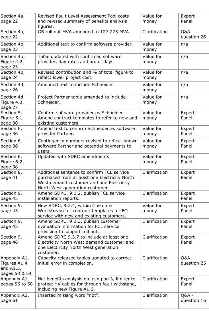
FLARE will propose changes to the Common Connection Charging Methodology to ensure that the cost allocation methodology for the new fault level mitigation techniques is defined. FLARE can have profound implications for the design and operation of distribution networks through the use of a centralized fault level assessment tool as part of. When the fault level rises above a specified value in a certain area of the network, the fault level assessment tool will enable or disable the fault level mitigation techniques.
The learning from FLARE will enable updates to the planning, design and operational standards for distribution networks, especially for HV networks facing fault level issues.
Customer impacts
Customer impacts continued
Successful Delivery Reward Criteria
Successful Delivery Reward Criteria continued
List of Appendices
Letters of support
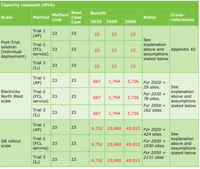
Appendix A1: Benefits Tables
It is believed that the method will eventually be applicable to sites where the switchgear is rated at the Design Fault Level or lower, representing 82% of Electricity North West's total population. Between 2020 and 2030 - It is assumed that it is appropriate to apply the Method to 25% of the remaining sites, as load forecasts indicate this. Based on the Electricity North West population, it is assumed that the method will be applicable to 63% of the UK population of bulk supply point substations where the switchgear is rated at design error level or lower.
Therefore, thermal capacity release is an alternative way to examine the capacity utilization released by the error space created by the method.
S -limiter benefits in terms of avoided HV cable replacement
Parsons Brinckerhoff was tasked with calculating the length of HV cable at risk for Electricity North West scale and GB scale rollouts. Electricity North West and GB the length of cables at risk is calculated with the following assumptions. The final total length of cables at risk based on the above assumptions was estimated to be 1975 km within the Electricity North West HV network.
The length of the cable at risk in the North-West Electricity system corresponds to 3 km per 11kV primary substation.
Appendix A2: Method and Base Case Methodologies
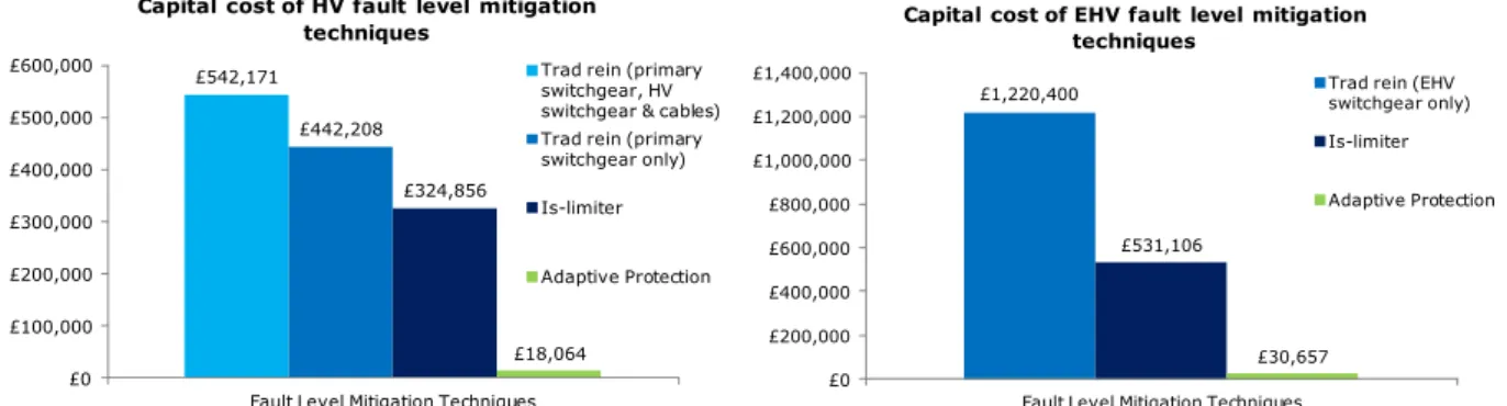
The average planning and installation for traditional reinforcement at HV and EHV is a year and a half ie 390 working days or 78 weeks. The average planning and installation time for Adaptive Protection on distribution switchgear is expected to take 20 working days or four weeks;. It is estimated that the planning and installation time for Adaptive Protection on electrical machines will take 20 working days or four weeks; the calculation of the protection settings will take half a week, and installation will take another three and a half weeks.
The average planning and installation time for IS limiters averages 90 days or 18 weeks.
Appendix A3: Tyndall
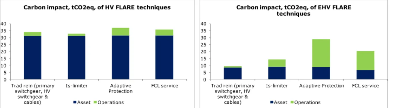
Manchester’s estimated carbon impact of FLARE
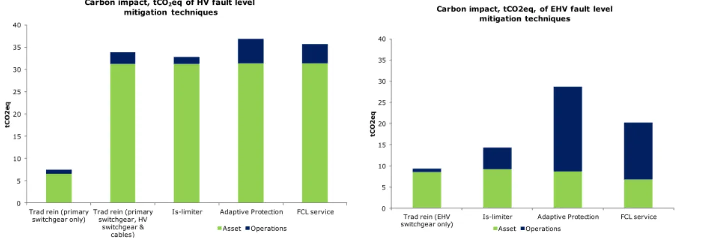
IS limiters are expected to be similar to traditional reinforcement on the HV network, with Adaptive Protection and FCL service. On the EHV network, IS limiters, Adaptive Protection and FCL service have greater impact compared to traditional reinforcement, but with a different distribution between assets and operations. Reinforcement cable is the dominant component of the carbon impact except in some EHV cases.
A preliminary scoping of the CO2 impact of FLARE suggests that assets rather than operations dominate the impact profile.
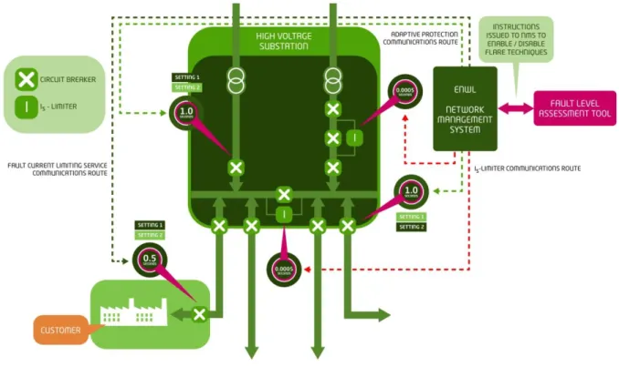
Appendix B1: Technical Solution
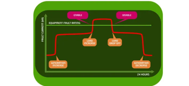
The fault level assessment tool will be located in the Electricity North West control room and is responsible for estimating the fault level in near real time. Devices in the field will provide all their data in real time to our NMS through the RTUs and this will be forwarded to the fault level. Network data will be provided to Electricity North West's fault level assessment tool in the form of CIM files.
This network model will be updated in accordance with our NMS to ensure it remains a true representation of the network.
Initial
Refine selection and
Initial screening
Substation classification
To increase the likelihood that the fault level mitigation technologies will work, the fault history of the substations/circuit will be analyzed to understand if the site would be a good testbed for the Trials, with the expectation that the new equipment for reducing error levels will work in the Trials. This criterion is only used to select sites for the Adaptive Protection Trials to ensure we get a mix of the different relay types. Using the list developed above, we apply the ages of the equipment and select at least one of each of the categories below.
Refine selection and peer review
The total number of sites where the fault mitigation technologies studied under FLARE will be deployed includes seven primary substations and two BSPs. 51 9.1.1 Instruct and train Electricity North West operations teams, including Planning Engineers, on failure mitigation management protocols by April 2016. ID Task Name Duration Start End Progress 53 9.1.5 Updated settings for failure level management, planning, design and security publishing and operation &.
170 9.5.2 Publish Electricity North West's approach to managing fault level amplification on FLARE website by October 2018.
Appendix D: Risks and issues register
Technology There is a risk that the installation of the new fault level assessment tool or the configuration of the network management system will be exceeded leading to a delayed start of live trials. Technology There is a risk that the new bug rate assessment tool will not perform as expected during testing and commissioning, leading to a delayed start of live trials. Technology There is a risk that the renewal of Adaptive Protection (for the distribution system and electric cars) may be more complex than.
Technology There is a risk that FLARE technologies will not perform as expected, leading to test circuits that exceed defect level limits.
Appendix E: Organogram
Appendix F: Project Partner Details
The terms and conditions governing the scope of participation and determining the default intellectual property rights of the LCN Fund. CHPA funds its support for customer identification and introductory access and additional knowledge. Work with PB and ENWL to test adaptive protection on CHP and prepare installation process/guidance for prospective CHP providers of FCL services.
ENER-G will fund the bench test of Adaptive Protection for CHP generation in the ENER-G test cell and provide engineering support for the testing.
Appendix G: I S -limiter safety case
The main problem with the Is limiter is that it is able to demonstrate its reliability to operate on demand without suffering from unacceptable levels of false trips. Should the Is limiter work as designed, there is no reason that would prevent its use in a network in the UK. Within a proposed three phase circuit breaker installation there will be one Is limiter per phase.
The Is-limiter is considered suitable for use in the UK based on its rated reliability and current use in Europe.
Appendix H: Withstand capability study
While it would be normal to adopt the relevant EN standard of a test duration of three seconds, in practice, on the North West Electricity network, the maximum is two seconds or less. The live tests were strongly supported by EPS for speed, connection to the North West electricity grid, cost and high (expected) integrity of results. ABB is delighted to have been selected as a partner to work with Electricity North West and other partners, to demonstrate Is Limiter, Fault Limiting Technology as part of the wider FLARE Project.
We look forward to learning and sharing with Electricity North West and its partners the further knowledge and understanding that the FLARE project will deliver.
Letters of support
Effective fault level management on the UK distribution system promises to provide improved capital efficiency, improved customer service and facilitate onward connection. ENER-G is pleased to join Electricity North West as a project partner for their low carbon grid project, Fault Level Active Response. As a distribution network operator (DNO), we are in constant dialogue with Elektriciteit Noordwest to find a connection for our generation products to theirs.
We will work with Electricity North West to support customer survey and analysis and customer engagement for the Fault Current Limiting service trials, plus the dissemination of learning from the FLARE project.
GMCA/AGMA LOW CARBON HUB
Milanović, CEng, FIET, FIEEE School of Electrical & Electronic Engineering Deputy Head of the School and Head of the Electrical Energy and Power Systems Group The University of Manchester.
Electricity North West plc
Appendix J: Common Connection Charging Methodology Change Proposals
Appendix K: FLARE Full Submission spreadsheet
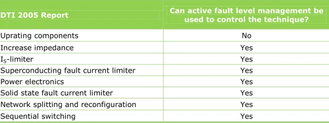
Appendix L: FlexDGrid and fault level mitigation techniques review
When the error level exceeds the ratings, we activate the relevant mitigation technologies, which will only work in the unlikely event that an error occurs. This active fault level management was considered as part of the FlexDGrid submission papers, but was discounted due to the need for system-wide modeling and reliable. Active error level control can be applied to the techniques of FlexDGrid as well as FLARE, which will further enhance the use of error level limiting techniques as shown in Figure L.2.
The outputs from FlexDGrid and FLARE will give GB a comprehensive set of solutions for fault level issues that will cater for all grid and business models ultimately giving generators a choice for their connection.
Appendix M: References
Appendix N: Glossary
This enables anyone interested in connecting generation or load to the grid to identify opportunities or constraints on the grid. Make capacity Maximum fault current that the circuit breaker can close on Near Real Time A measure of the frequency of the calculation by the Fault Level. Primary substation A point on the network where the voltage changes from 33kV to 11kV or 6.6kV.
Substation A point on the network where voltage transformation takes place Switchgear Device for opening and closing electrical circuits (including circuit breakers).
List of Changes
Confirm software provider as Schneider Modify contract templates to refer to new and existing customers. Net-benefit analysis on using an IS limiter to protect HV cables against fault resistance, including new Figure A1.6.