To overcome this problem, this paper proposes two software tools for GD systems, namely (1) a sketch-to-program correlation tool that allows architects to use sketches and combine them with code, and (2) an instant feedback tool that speeds up the effect of actions in the output of the program. We found that while the first tool turns program documentation into a less tedious task, it consequently reduces the lack of documentation in GD programs; the second tool improves program visualization and creates a new medium to help people design programs.
Problem Statement
Generative design programs, by definition, can itself be considered a description of a design, as it formally specifies the design modeling process. One result of the lack of program documentation is that programmers must spend a considerable amount of time separating relevant ideas from irrelevant ones.
Objectives
These sketches are linked to the source code of the program in a way that significantly reduces the effort of reading the code. This tool minimizes the delay between writing code and its execution, which in turn encourages users to quickly experiment with ideas, increasing their understanding of the program.
A Programming Framework
The first part discusses the basics of teaching programming to beginning students and the relationship between programming and related issues. It should be read primarily by types, i.e. knowledge of planning methods (necessary for program design).
Coding in Architecture
Programming System
General-purpose systems
Eclipse
In the literature, a similar concept, known as liveness (Alpern and Schneider, 1985), refers to the ability to change a running program. The complexity of installing and configuring an IDE negatively affects the programming language itself, because users are more interested in the capabilities of the language than the IDE.
LightTable
This feature is based on the old idea of Lisp environments: the read-eval-print loop (REPL) which is a request used to test language expressions without having to execute all the code. The real-time debugger is an interactive way to debug code and understand program flow.
Teaching systems
- LOGO
- SmallTalk
- Processing
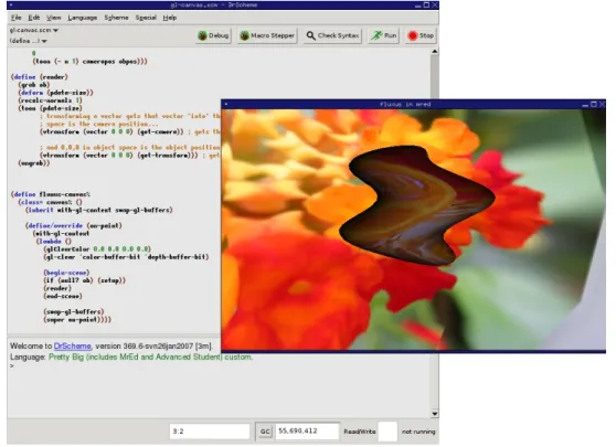
- Fluxus
- DrRacket
- PythonTutor
- YinYang
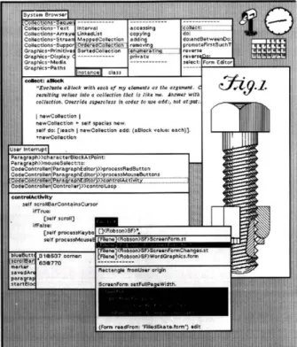
This approach goes further by using reflection mechanisms to track the function call values and display them populated in the function template (as shown in Figure 3.3, the stream of values produced by calling(x 3 7)). It annotates programs with font and color changes based on the syntactic structure of the program. Consequently, the learner may expend significant mental effort to understand insignificant details of the language.
Empowering Systems
- DesignScript
- Monkey
- Rosetta
- Grasshopper
- Dynamo
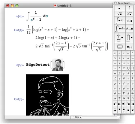
- Mathematica
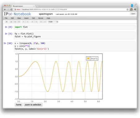
- IPython
- MathCAD
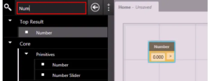
As the user interacts with the components, adding and connecting them, the result is immediately reflected in the CAD model. This mechanism is useful for design exploration because it maintains an old replica of the changed geometry in the background of the CAD. IPython's architecture is a typical client-server, where the frontend is the client (i.e. the notebook) and the server is a language kernel (i.e. the programming language with which users communicate).

Summary
This means that variables have a global scope, the MathCAD document, if a variable is changed anywhere, it will be changed at every occurrence in the document. Environments in our study used several techniques to help users understand the behavior of their programs. These included (i) a debugger that helps to find errors in the program, (ii) an enhanced debugger that provides live execution feedback, (iii) strong metaphor language that allows physical interpretation, (iv) immediate visualization of models , (v) navigation through program execution (vi) assemble components of a data flow paradigm and (vii) present data adequately. 4) What does code look like in the programming environment or language? The systems in our study represent programs that use text that users can type, graphical components that users can manipulate, and mathematical forms that users can fill out.
Conclusion
This chapter presents the design of a coherent system that incorporates the previously studied techniques for interactive programming. The first part discusses the importance of good design principles in software engineering, highlighting the lack of tools that enforce these principles in current programming systems, especially in the field of architecture, where programming methods are increasingly popular. While the next chapter discusses the technical aspects and architecture of the software, this chapter goes into more detail about the rationale behind all design decisions.
Design Principles: a recurring need
Program Documentation
Tools for documenting software programs
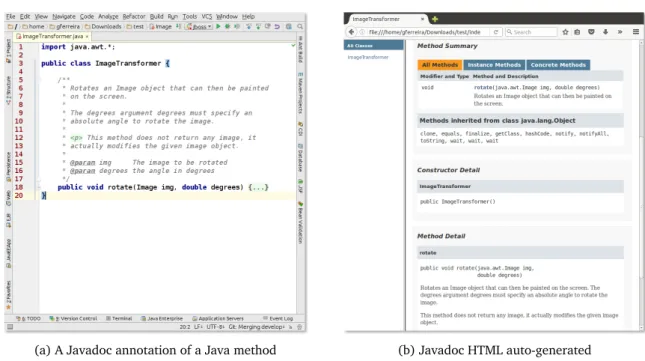
So, to generate the documentation, the comments must be inside these tags (as shown in Figure 4.1a). As a result, these tags add proper information to the HTML page (eg as shown in Figure 4.1b). On the other hand, Codelets (Figure 4.2b) use media-rich resources to present a variety of icons that developers can choose to create their web pages in a popup.

Tools for documenting Generative Design programs
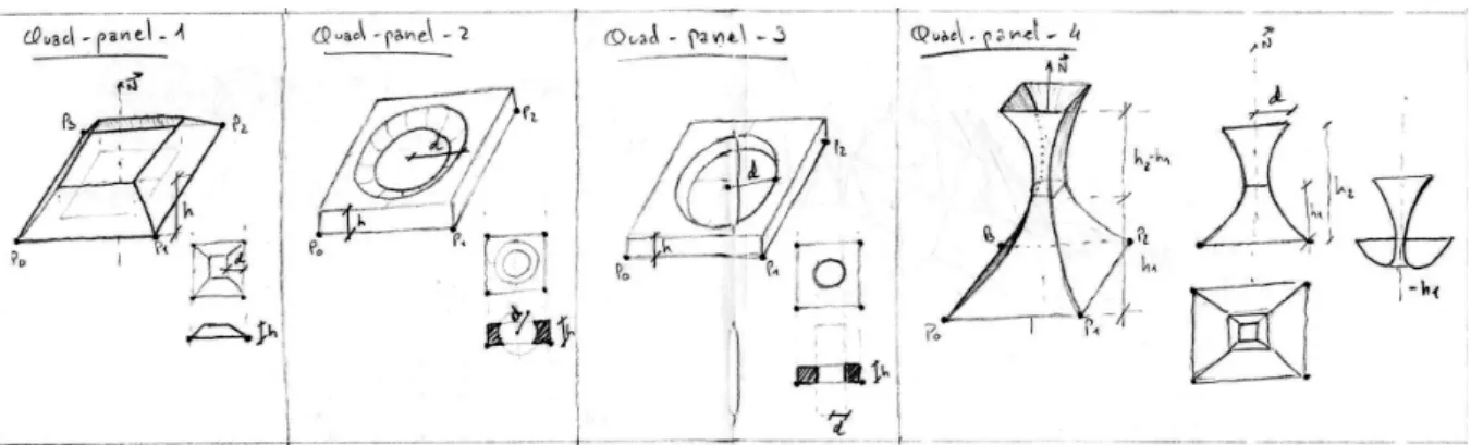
Using this example, the architect can create an appropriate GD method that creates this chair seat. For example, Listing 4.1 illustrates a function that models a chair seat with some of the parametric variables from Figure 4.4. Therefore, when we look at this piece of code and compare it with the image, we understand the meaning of each variable in the context of the function.

An approach for documenting Generative Design programs
- Sketch-program correlation tool
- Dealing with images resources
- Automatically binding code with images
- Designing a fallback mechanism
- Presenting binding associations
- Strategies to improve the usability in the source code editor
For example, one of the first challenges is how to embed images in the code editor. The programmer can therefore intervene directly in the image recognition process to help the OCR with errors. Therefore, adding rich media resources in the source code can interfere with the navigation.

Immediate feedback
- Immediate feedback in Generative Design
- Immediate feedback tool
- The activities of program experimentation
- Improving program execution
- Program experimentation in Generative Design
- Inline sliders mechanism
- An inherent problem
- Adaptive sliders
- Dealing with errors
The purpose of this tool is to significantly reduce the time between a change in the code and its effect in the program execution. Moreover, this mechanism is independent of the program execution, which means that dragging the slider will only make changes in the code. This strategy had a better performance, but it limits the program experimentation to individual points in the range of the slider.

Conclusion
In this situation, there are two options: (1) stop the experimentation and introduce an error, or (2) release the error and allow the programmer to continue with his task. This chapter presents a coherent implementation of the proposed software tools, exploring the ideas proposed in the previous sections. The last part describes the test conducted with target users to verify the initial hypothesis.
Rosetta
Despite the promising results shown in Table 5.1, at this moment the OpenGL backend is still being developed in Rosetta, and only supports a subset of the functionality provided by the other backends. For example, Figure 5.5 illustrates a typical scenario where the user selects an expression in his program and Rosetta displays the set of shapes that resulted from that expression. Note that this set contains all shapes created by the expression during the complete execution of the program.

DrRacket
The marked cylinders (on the left, in yellow) are produced by the marked expression (on the right, in blue). For example, the debugger, the syntax checker and the stepper, despite providing different functions, are implemented on top of the same API. However, the syntax checker ignores the comments category, including its visual elements such as the images.

Implementing the proposed tools
Program-sketch correlation tool
The parameter illustrated in the image (in the cc symbol, under the cursor) is highlighted in the code (in green, using blue arrows). The first approach taken followed this description, sending sketches, such as the one shown in Figure 5.8, to OCR. For example, Figure 5.14 shows exactly this moment, after the picture has been inserted into the body of the function.

Immediate feedback tool
Despite the noticeable difference between the generated forms, the function used to create them is the same (this function is also shown in Figure 5.10). For example, consider the orthogonal cones function (shown in Figure 5.10), its execution time is relatively simple (e.g., it is a tolerable delay during the model update, but using more complex geometry, such as the Möbius lattice in Figure 5.4, or even complex geometry such as a building, execution time can increase significantly, and immediate feedback becomes almost impossible.

Implementation Details
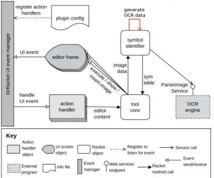
- General architecture
- Binding association
- Image-data-snip
- Auto Run
On line 5, the two constants 0.5 define the center position of the arrow in image space. The image-data-snip% class, shown in Figure 5.22, plays a fundamental role in the connection between image and code. In addition, this class defines a base for other functions that manipulate or even edit the image inserted in the text editor.
Conclusion
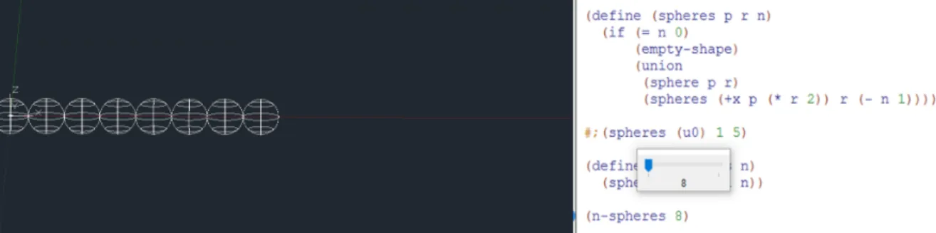
Second, when on enable mode, it tries to execute the code on every change. Finally, to improve this tool, an interactive mechanism has been implemented to provide input to the program, using the DrRacket slider widget. So, when the slider is dragged, the editor changes, causing the AutoRunplugin to execute the code.
The experiment
This chapter completes the implementation, evaluates these tools with practical experiments, namely the use of the sketch-program correlation tool to illustrate GD programs, and the immediate feedback tool to interactively generate geometric models.
Program-sketch correlation tool
To use this tool, the architect simply moved her sketches into the function body, corrected the bindings, and clicked the Check Syntax button. While the sketches used in the previous examples were deliberately made to illustrate the context of that function, Figure 6.4 shows a sketch at an early design stage. On the right, the sketch was collapsed reducing the function to a few lines of code.

Immediate feedback tool
The slider was used to change the factorial input, displaying the result in the interactions window. The denominator of the angle is modified to 3, producing, on the right, the shape of the turbine with its fans set over a circumference of 2πradians. The denominator of the angle is modified to 6, producing, on the right, the shape of the turbine with its fans set over a circumference of πradians.
Conclusion
On improving the interface to the source code of computer programs,” in Proceedings of the SIGCHI Conference on Human Factors in Computing Systems. Brandt, "Codelets: link interactive documentation and example code in the editor," in Proceedings of the SIGCHI Conference on Human Factors in Computing Systems. Sorensen, “Impromptu: An Interactive Programming Environment for Composition and Performance,” in Proceedings of the Australasian Computer Music Conference.