An Investigation on the Inaccessibility Characteristics of Standard Token-Based LANs
INESC Technical Report RT 26-92 J. Rufino, P. Ver´ıssimo
April 1992
LIMITED DISTRIBUTION NOTICE
This report may have been submitted for publication outside Inesc. In view of copyright pro- tection in case it is accepted for publication, its distribution is limited to peer communications and specific requests.
An Investigation on the Inaccessibility
Characteristics of Standard Token-Based LANs
Jos´e Rufino, Paulo Ver´ıssimo Technical University of Lisboa
IST/INESC∗
e-mail:[email protected], [email protected]
Abstract
Local area networks have long been established as the basis for distributed systems. Conti- nuity of service and bounded and known message delivery latency are requirements of a number of applications, which are imperfectly fulfilled by standard LANs. Most previous studies have assumed only a normal LAN operation in the derivation of worst-case access/transmission de- lays.
However, LANs are subject to failures, namely partitions. Since most applications can live with temporary glitches, reliable real-time operation is possible on non-replicated LANs, pro- vided that these temporary partitions are time-bounded. We call these periods of inaccessibility, to differentiate from classical partitions.
This work investigates the inaccessibility characteristics of a given set of standardised token- based local area networks, namely ISO 8802/4 Token-Bus, ISO 8802/5 Token-Ring and ISO 9314 FDDI. This study allows, for each one of the mentioned LANs, the derivation of a worst-case inaccessibility figure, to be added to the worst-case transmission delay in the absence of faults.
The study is interesting on the grounds that it provides a basis to predict LAN performance in the presence of failures, and provides guidance on how to improve the inaccessibility time figures.
1 Introduction
Local area networks have long been established as the basis for distributed systems. The several variants of standardised LANs (ISO 8802 and FDDI) have different mechanisms to control access to the medium and recover from errors. Continuity of service and determinism in transmission delay are requirements of a number of applications, specially in the fault-tolerance and real-time area, which are imperfectly fulfilled by these LANs, if used without special measures. A number of authors have studied problems such as priority inversion [37], probability of meeting estimated access times [23, 29], extensions for medium failure resiliency through redundancy [51], potential lack of determinism [33].
In reliable real-time systems, the fundamental requirement of communications is that there be a bounded and known message delivery latency, in the presence of disturbing factors such as overload or faults. When the requirement is very strict (eg. for life-critical applications), specialized space-redundant architectures are the solution: point-to-point graphs [30] or multiple LANs [5].
These solutions are however costly and complex. In spite of their limitations, standard LANs are a very important design component. It is worthwhile investigating if the real-time requirement
∗Instituto de Engenharia de Sistemas e Computadores, R. Alves Redol, 9 - 6o- 1000 Lisboa - Portugal, Tel.+351- 1-3100000. This work has been supported in part by Junta Nacional de Investiga¸c˜ao Cient´ıfica e Tecnol´ogica (JNICT) through Programa Ciˆencia.
can be reliably met in local area networks that are not replicated, except for eventual medium redundancy — at the electrical signalling level. To achieve reliable real-time communication, three fundamental conditions must be validated:
1. bounded delay from request to transmission of a frame1, given the worst case load condi- tions assumed;
2. message2 delivery despite the occurrence of omission failures (eg. lost frames);
3. control of partitions.
Most of the existing studies with this regard have addressed point 1 [23, 16, 6, 22]. However, they are helpless at representing the LAN behaviour, when faults occur. In that case, it is necessary to study the patterns for omission failures (eg. number of consecutive omission failures) and for partitions. Uncontrolled omissions and partitions are a source of asynchrony and inconsistency.
This is unacceptable for most systems, let alone real-time ones. Point 2 is addressed under the scope of the LLC type 3 service for point to point interactions. However, it has been practically disregarded for broadcast or multicast interactions. One exception is a modified token-ring mecha- nism described in[17]. Point 3, when regarding non-replicated networks, and to the best of authors’
knowledge, only recently has deserved some attention.
All three points have been addressed in [50] for LANs in general, while point 3 has been specifically addressed in [40] for Token-Bus LANs. Token-bus, given its connection with MAP, is very relevant in control and automation3, where all these points assume a particular importance.
In this paper we review our original study on token-bus error handling performance and extend that study to a set of standardised token-ring networks, namely the ISO 8802/5 Token-Ring and the ISO 9314Fiber Distributed Data Interface(FDDI). This study contributes therefore to a better understanding of these LANs operation with regard to their real-time, reliability and accessibility attributes.
2 Controlling Partitions
A network is partitioned when there are subsets of the nodes which cannot communicate with each other4. In this sense, a single LAN displays a number of causes for partition, not all of them of physical nature, like bus failure (cable or tap defect): bus contention, ring disruption, transmitter or receiver defects; token loss; etc. Some LANs have means of recovering from some of these situations, and can/should be enhanced to recover from the others, if reliable real-time operation is desired.
However, the recovery process takes time, so in the meantime the LAN is partitioned. A solution to the problem of controlling partitions was presented in [50]. It is based on a very simple idea: if one knows for how long a network is partitioned, and if those periods are acceptably short, real-time operation of the system is possible.
Let us call them periods of inaccessibility, to differentiate from classical partitions. The defini- tion of inaccessibility in [49] is summarised here:
Certain kinds of components may temporarilyrefrainfrom providing service, without that having to be necessarily considered a failure. That state is called inaccessibility. It can be made known to the users of the component; limits are specified (duration, rate); violation of those limits implies permanent failure of the component.
1LAN level information packet.
2User level information packet.
3Manufacturing Automation protocol
4The subsets may have a single element. When the network is completely down, all partitions have a single element, since each node can communicate with no one.
This is not hard to implement, as shown in [50]. To achieve it one must first assure that all conditions leading to partition are recovered from. For example, tolerance to one medium failure is directly assured in the dual FDDI ring [15]. A similar approach has been envisaged in [1] for the IBM Token-Ring, which is similar to the ISO 8802/5 Token-Ring. In a token-bus network some extensions have to be implemented, since it has no standardised redundancy. For example, we devised a glitch-free method for real-time switch-over between buses of a dual-media token-bus [51].
Then, one needs to show that all the inaccessibility periods are time-bounded and determine the upper bound. Three relevant case studies, comprehending the aforementioned standardised token- based networks, are presented next. The scenarios described are essentially the inaccessibility periods foreseen in the corresponding standard specifications. The figures presented illustrate the intervals in the network operation when the LAN does not provide service, although not being failed.
The study yields interesting conclusions, like: a figure for the worst case duration of inaccessi- bility (to be added to a worst-case access time...); the existence of some periods much longer than average; strategies to reduce the longest periods are possible.
3 Case Study: Token-Bus
The ISO 8802/4 Token-Passing Bus is a local area network (LAN) which has gathered a growing attention after it has been selected as the communication infra-structure of MAP, the Manufacturing Automation Protocol, becoming then a standard for interconnection and interworking in the factory floor [34].
Access control is performed by a token passing protocol, which establishes a logical ring over the physical bus. Access to the shared broadcast medium for data transmission is only granted to the station which currently holds the token. A timed-token mechanism is used to guarantee an upper bound on access delay to the network. This bound is unfolded with successively lower guarantees, in four classes, through priorities.
The efficiency of this scheme has been studied in the last few years, either through simulation work [3] or analytical models [23]. The performance of the token bus priority scheme [4, 24, 25]
has also been studied. Analytical approximations for the mean frame delay, under different service disciplines, are proposed in [52].
Most of these studies assume that the network always operates normally, neglecting the influ- ence of inaccessibility. However, in the presence of faults corrective actions must be performed and in consequence the operation of the logical ring is affected, sometimes severely, in the sense that it can no longer ensure the calculated frame transmission delay bound.
An analysis of the Token-Bus error handling mechanisms is provided in[38]. However, it is only qualitative. A comprehensive quantitative analysis of the 8802/4 error handling mechanisms is the central issue of this case study.
Data Rate Bit Time Octect Time Station Delay (M bps) tbit (µs) toct (µs) tSD (µs)
5 0.2 1.6 11.3
10 0.1 0.8 20.9
Table 1: Station Delay for a MC68824 Token-Bus LAN controller
Network Characterization
For our purposes, two important parameters characterize the basic operation of any ISO 8802/4 Token-Bus network:
Data Rate- The rate of data signalling, in the bus. It gives a meaning to the bitand octecttimes.
A wide set of MAC protocol timers are scaled by these timing references [19].
Slot Time- This parameter is set up by station management entities. It is an aggregate variable accounting for medium access control (MAC) sub-layer intrinsic performance and network size. The slot time is usually expressed in octect times, due to its formal definition, provided in [19]. In this work, for simplicity, we use its value expressed in plain time, as given by equation:
tSlot= 2.(tP D+tSD) (1)
• tP Dis the worst case end-to-end propagation delay of the physical layer. This variable accounts for the network cable propagation delay, plus the modem delays (at both transmit and receiver ends) and the regenerative repeater delay, whenever used. For the length-dependent cable propagation delay a typical value of 5µs/kmis assumed.
• tSD is the station delay. This variable accounts for the intrinsic performance of each particular MAC VLSI implementation. The values presented in Table 1 refer to the Motorola MC68824 Token Bus Controller [46]. A typical scenario is considered: the TBC, in addition to token passing, is also performing data transmissions mixed with ring management actions.
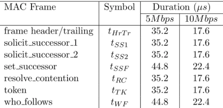
MAC Frame Symbol Duration (µs)
5M bps 10M bps frame header/trailing tHrT r 35.2 17.6 solicit successor 1 tSS1 35.2 17.6 solicit successor 2 tSS2 35.2 17.6
set successor tSSF 44.8 22.4
resolve contention tRC 35.2 17.6
token tT K 35.2 17.6
who follows tW F 44.8 22.4
Table 2: Duration of MAC Token-Bus Protocol Data Units (ladd = 48)
MAC Protocol Data Units
Several types of protocol data frames are exchanged between peer MAC entities, in order to provide logical ring housekeeping functions, essential for normal ring membership management, and for the preservation of ring integrity in the presence of faults. These functions are supported through the following set of actions:
– Solicit new stations for logical ring entry.
– Find out the successor of a failed station (who follows).
– Solicit any station to respond at successor querying.
– Resolve contentions.
– Establish a new successor.
– Bid for token generation.
– Token passing.
The duration of all MAC protocol frames which take part in these actions, exception made to token claiming, are presented in Table 2, for an address length (ladd) of 48 bits. The values were computed based on frame length and data rate, assuming that fast synchronising modems are used.
A three octect preamble, required to fulfill the minimum 2 µspreamble duration at 10 Mbps [19], is considered at both data rates.
Token-Bus Accessibility Constraints
In this section we will cover a set of scenarios leading to network inaccessibility. For many of them we start with very simple situations that then evolve to less restrictive – and thus more realistic – operating conditions/fault assumptions. For most of the cases, the main analysis is completely general, being particularized for best and worst cases, afterwards.
Addition Of New Stations
Each station on the logical ring periodically offers other stations the opportunity to become ring members. This operation is performed through a controlled contention process called solicit successor procedure which allows non-participant stations to declare their wish of being admitted into the logical ring. The value of a special counter within the MAC sub-layer controls how often a ring member can perform management operations5. The process is initiated by the then-current token holding station and its operation varies slightly depending on whether or not this station is the one having the lowest address.
Let us consider in first place the case where the current token holder does not have the lowest address, in the network. In such a case, the current token holder issues a solicit successor 1 frame with the destination address set to its successor, waiting afterwards for possible responses during a window of one slot time.
Any station waiting to become a ring member, compares the addresses of the received so- licit successor frame with its own address. Only those stations whose individual address falls in the range between the addresses of the current token holder and its successor will respond to the query6 through the issuing of a set successor frame. Three distinct situations may then occur:
◦ No station answers- In this case no set successorframe is received and the station simply passes the token to its former successor, after a one-slot time delay.
◦ Exactly one station answers- Upon the receipt of the set successorframe the station updates its next station[19] variable and passes the token to this new successor. After receiving the token, the new ring member can start using it.
◦ More than one station answer- Contention arises when multiple stations simultaneously answer to the solicit successor query and, in consequence, only unrecognizable noise may be heard during the response period. Contention is detected by thesolicit successor senderand resolved through an arbitration algorithm which we will describe ahead. Once contention is resolved, ring management operations proceed, with the actions described in the previous case.
The first inaccessibility situation thus occurs when the MAC sub-layer, performs the actions required for the addition of a new station. The duration of the resulting inaccessibility period is
5Theinter solicit counter[19] is decremented one unit in each token rotation; when it reaches zero, ring manage- ment operations can begin, if there is available bandwidth, i.e. provided that the time elapsed since the last token visit is lower than the associatedtarget token rotation time [19]. This can inhibit a large number of stations from performing ring management during a single token rotation.
6This restriction aims at preserving the descending order organization of the logical ring. It also serves to reduce the number of possible contenders.
given by equation 7:
tina←join1=tSD+tSS1+tSlot+trcp (2) The exact duration of the resolve contention process – trcp – depends on whether or not a contention between stations occurs and on how quickly this contention is resolved. Contention is detected by thesolicit successor senderand its resolution is started by issuing aresolve contention frame. This action opens four response windows. The contending stations start to use the first two bits of their station addresses, in order to establish which of the four response windows they will use to respond, with aset successorframe. Theresolve responder algorithmschedules stations with higher T woBit values to respond sooner. Any station that hears bus activity, before issuing its response, withdraws from the contention process. If a station hears no activity until the moment when it should issue the response, it transmits theset successor frame. The process ends when the token holder, at the end of a contending round, detects a valid set successor frame. A contending station detects that it has won the contention when it receives the token. The resolve responder algorithmis won by the first station heard without errors8, usually the contending station with the highest address, and the average time spent in its resolution can be estimated by the corresponding line in equation (3), where we have considered that responses are only received near the end of the fourth slot time during 1/4 of the rounds9:
trcp=
0 no response
tSSF no contention
X
nbrounds
(tRC+ 4. tSlot+tSSF
4 ) contention
(3)
An upper bound can be placed on trcp. This bound, that we signal with superscript wc, is obtained by considering that competing stations, with addresses differing only in the last two bits, systematically respond in the fourth window to the resolve contention request:
twcrcp=
(ladd/2)
X
i=1
(tRC+ 4. tSlot+tSSF) (4)
Let us now consider the scenario where the station which triggers thesolicit successor procedure is the one having the lowest address in the network. It is the only station where its own address is lower than its successor’s. In consequence, a slightly different ring management procedure is required, so that both stations with addresses below its own and stations with addresses above the highest one may enter. The differences are only in the way the process is initiated:
— The station with the lowest address begins thesolicit successor procedureby transmitting asolicit suc- cessor 2frame addressed to its successor, i.e. the station with the highest address in the network, and waits for possible responses during two consecutive windows.
— Stations with addresses below the token holder respond in the first window.
— For stations with addresses above the token holder successor the issuing of possible responses is delayed by one slot time. If these stations hear no activity in the bus during this period, they issue their responses during the second window. Otherwise, they abandon the process.
7The value oftSD, accounting the overhead needed by a station to enter in ring maintenance, may represent a slightly pessimistic upper bound. Its straight utilization however, does not significantly influence overall computations.
It simply aims to avoid the introduction of network parameters not defined in [19].
8This is the way the standard specification is written. However, a conformant station may use, instead, any correctly receivedset successorframe [19].
9Thus spreading out from the four window period.
The remaining aspects of the process, including the resolution of possible contentions, do not differ from the previous case and therefore the expression for the inaccessibility time is given by:
tina←join2=tSD+tSS2+ 2. tSlot+trcp (5) The upper bound for the inaccessibility time, due to the addition of a single station into the logical ring, can be easily obtained from the previous equations:
twcina←join=tSD+tSS2+ 2. tSlot+ladd
2 (tRC+ 4. tSlot+tSSF) (6) The solicit successor procedure always adds new stations to the logical ring in a one by one basis. Requests for logical ring entry, issued by several stations in the same response window, beyond leading to a contention process, also originate a compound set of actions where the various ring entries may or may not be sequenced in the same token rotation. This is a complex process whose thorough analysis will be performed next.
Multiple Joins
When a station joins the logical ring through the process described in the previous scenario two important actions, decisive for subsequent management operations, are performed upon ring entry:
• Theinter solicit counter of the new ring member is set to zero.
• Its token rotation timer for ring maintenance is set to a special value, furnished by station management entities, known as ring maintenance timer initial value[19].
After receiving the token the new ring member checks all its user access classes, looking for any enqueued traffic, and finally checks whether or not it should open a window for ring management.
Since the inter solicit counter has been set to zero on ring insertion, this decision will only be affected by the availability of network bandwidth.
Nevertheless, each station is provided with the aforementioned dedicated facilities for band- width control upon ring entry and, in consequence, it can be parameterized either to immediately start a new solicit successor procedure or to postpone it until a forthcoming opportunity. In this latter case multiple competing stations will only be admitted, one at a time, when there is available bandwidth.
Conversely, when a station is parameterized to start a solicit successor procedure upon ring entry, all the competing stations will be admitted in the same token rotation, with each new member immediately promoting the admission of a new successor, until all the stations have succeeded in entering the logical ring. The normal token rotation is thence slowed down by the amount of time given in equation (7).
tina←mjoin= X
Nst→join+1
tina←joinx (7)
In this expression, the index under the sum symbol represents the number of ring management rounds performed upon the addition ofNst→joinstations to the logical ring. The value oftina←joinx
will be given by equation (5) as long as the station leading the process is the one with the lowest address in the network. Otherwise, it will be expressed by equation (2).
In a network with Nst active stations, allowing a maximum number of NST stations, the time spent for the addition of all the remaining (NST −Nst) stations, in the same response window, is
upper-bounded by equation (8). This expression accounts for the duration of the first (NST−Nst−1) contending rounds, the duration of the last station join and also the time spent by this station in the final opening of a window to which no station will respond. This result is thus slightly different from the one which can be obtained for (NST −Nst) independent joins10.
tubina←mjoin = (NST −Nst−1). twcina←join+tSD+tSS2+ 2. tSlot+tSSF + tSD+tSS2+ 2. tSlot
= (NST −Nst−1). twcina←join+ 2.(tSD+tSS2) + 4. tSlot+tSSF (8) The function given by equation (8) decreases with increasing Nst. Therefore the worst-case scenario is obtained whenNst = 2 and a massive join demand occurs11, although such a situation will only arise in the power-up of the given set of stations. The time spent in the addition of those stations to the logical ring is expressed by equation:
twcina←mjoin= (NST −3). twcina←join+ 2.(tSD+tSS2) + 4. tSlot+tSSF (9) The best case scenario, for multiple station joins, is obtained when two stations enter the logical ring, in the same maintenance opportunity, without contention. Contention will only be avoided if one of the joining stations has an address smaller than the lowest station already in the network, while the other one has an address greater than the highest station. The station with the smaller address responds first and enters the logical ring without contention, promoting afterwards the entrance of the station with the higher address. The time spent in these operations is given by equation (10).
tbcina←mjoin= 2. tina←join2(no contention) +tina←join1(no response) (10) Station Leave
Stations may leave the logical ring either in an abrupt or orderly way. Abrupt leaves usually result from station failure and they will be dealt with in coming scenarios.
An orderly leave from a logical ring is only possible when that station holds the token. Station withdrawal is achieved through a ring patch between its predecessor and successor stations. For that purpose, the leaving station before passing the token issues a set successor frame, addressed to its predecessor, and carrying the address of its future successor. The inaccessibility time due to the leave operation is very short and it is simply given by:
tina←leave=tSD+tSSF (11)
Multiple Leaves
Station leaves can always be executed whether or not there is bandwidth available for ring management operations. Therefore, if several stations want to abandon the logical ring in the same token rotation they are always allowed to do it. This means that the normal token rotation time will be slowed down by the time spent in these actions, which is given by:
10The occurrence of a high number of independent joins, in the same token rotation, is not likely to happen. In part this is due to the limit usually placed on the available network bandwidth; in part it is because a small randomizer is used within MAC to dither themax inter solicit counter [19] from its nominal value, once every 50msor after its use, which minimizes the clustering of windows opening in the same token rotation.
11These results are derived in the assumption that a logical ring already exists.
tina←mleave =Nst→leave. tina←leave (12) whereNst→leave represents the number of stations that will abandon the logical ring in the current token rotation. Its value is upper bounded by (Nst −2) and therefore the worst-case value for multiple station leaves can be obtained with equation (13).
twcina←mleave= (Nst−2). tina←leave (13)
No Successor
A station holding the token may transmit during an allowed period of time. Afterwards it should pass the token to its successor. If this station is failed, the token passing operation will not succeed. After the token pass checking period (one slot time) has elapsed a recovery strategy is tried. This includes the repetition of token transmission (checked during one more slot time) followed by a variant of thesolicit successor procedure. During thiswho follows query the current token holder waits for aset successorframe, until the end of a three-slot-time period. Under a single station failure assumption, the current token holder will receive, within this period, a response from the successor of the failed station. This establishes a new successor for the current token holder and ends the recovery procedures. The time spent in performing these actions is given by:
tina←nosuc=tSD+ 2. tT K+tW F + 5. tSlot+tSSF (14) Token Loss
In the previous scenario we have considered that a station is not holding the token when it fails. We now consider that a station fails while it is holding the token.
Token losses are detected by monitoring the absence of bus activity and recovered through a claim token process [19]. The duration of the whole process is given by:
tina←tkloss =tBIdle+ttcp (15)
• The first term on this expression represents the time elapsed between the loss of the token and the beginning of the token claim process. It corresponds to the value loaded into the Bus Idle Timer.
Usually this timer assumes the value of seven slot times. The exception is the station having the lowest address in the network, where theBus Idle Timeris loaded with only six slot times12.
tBidle =
6. tSlot lowest station present 7. tSlot lowest station failed
(16)
• The second term represents the duration of the token claim process. Any station where theBus Idle Timerexpires, initiates a recovery procedure by issuing aclaim tokenframe whose length depends on the first two bits of the station address. After issuing its request the sending station waits during one slot time. If at the end of this period the station detects activity in the bus, then it drops out from the token claim process. If no activity is detected and there are unused bits in the address string, the station repeats the process using the next two address bits. The process ends after the winning station has used all the bits of its address, plus two randomly chosen bits.
12This procedure aims at avoiding collisions during thetoken claim processby allowing one station to start it in isolation. Since the station processing the event is the one having the lowest address, the generation of a new token will be performed more quickly, as we will see ahead.
The time spent in these actions is given by equation (17), for stations having an address length ofladd
bits. The firstladd/2 iterations use the station address bits, to define the length of the claim token frames. The last iteration employs a random two-bit value.
ttcp=
(ladd/2)+1
X
i=1
(tCF(i) +tSlot) (17)
– tCF(i), represents the duration of aclaim token frame issued in roundi, and is given by:
tCF(i) =tHdT r+ 2×T woBitadd(i)×tSlot
wheretHdT rstands for the duration of the MAC header/trailing sequence. TheT woBitaddvalue can range from zero to three.
When the lowest address station is not present in the network, probably due to its failure, the address sort algorithm used by the token claim process always leads to the selection of the station with the highest address as the token user. The worst-case value can then be obtained by considering that the station which wins the contention has the highest possible address:
twcina←tkloss = 7. tSlot+ (ladd
2 + 1) (tHrT r+ 7. tSlot) (18) The best-case value can also be obtained, considering that a station with all its address bits set to zero is present and active. The recovery time, from a token loss, will then be given by:
tbcina←tkloss = 6. tSlot+ (ladd
2 + 1) (tHrT r+tSlot) (19)
Fails while holding the token
Sn Sn-1
Sn-2 S3
S2 S1
Figure 1: Side-effects of Token Loss Recovery
Let us now analyze some side effects that token recovery may have on the normal token circu- lation. Consider the token bus network, whose logical ring is pictured in Fig. 1. Station S1 has the highest address, while stationSn has the lowest one. Additionally, consider that station Sn−2 fails while holding the token. The claiming of a new token is started after the bus idle timer has expired in some station, and since the station with the lowest address on the network is not failed, the token claim process will be initiated and won by this station.
StationSn−1, which was about to receive the token when the failure of its predecessor occurred, is passed over. So, in addition to the token recovery time, station Sn−1 must wait an extra token rotation to get access to the network. This means that different stations in the network may have
a different view of inaccessibility and that, as a general rule, the inaccessibility time may not be merely represented by the time required to recover the token. On the other hand its worst-case value, as given by equation (18), must be consolidated with the addition of the network access delay upper-bound.
The token rotation which immediately follows the token recovery process is of fundamental importance for network operation, even if there are no skipped stations. Depending on their values, some or all of the lower priorityTarget Token Rotation Timersmay have expired during the recovery process and if so, no bandwidth is available for those access classes. The first token rotation will then restart theTarget Token Rotation Timers. The access to the network, immediately after token recovery, is thus only assured for the highest priority access class13. During this token rotation, a second inaccessibility period, corresponding to a no successor scenario, will occur. It is a direct consequence of the primary failure and arises when the predecessor of the failed station tries to pass it the token.
Multiple Failed Stations
So far, we have considered that only one station in the network fails at a given time. Let us now consider a less restrictive scenario by allowing the failure of multiple stations. To be compliant with our initial single failure assumption we will consider that all these multiple failures happen at the same time, due to some common cause. Common mode failures are realistic enough to be taken into account. Consider, for instance, a network where several stations are connected to the same power supply line. A failure or a shutdown in this line will bring all these stations down.
S1 S2 S3 S4 S5 S6 S7
Failed Station
Figure 2: Example of a multi-failure scenario
Let us, for the moment, additionally assume that none of the failed stations are adjacent in the token-passing order. In consequence all the failures can be recovered through successive who followsqueries. Between each recovery action non-failed stations may transmit data, provided there is available bandwidth. This means that inaccessibility periods may alternate with the flow of data in the network. As in the previous case the view that ring members get of inaccessibility is not consistent among all the stations.
The current token rotation is slowed down by the amount of time needed to perform all the who followsqueries. The time spent in these successive queries grows linearly with the number of
13The 8802/4 MAC protocol guarantees that any station may hold the token during a fixed amount of time, for servicing the highest priority class. Service of lower priority ones, including the management of station joins, can only be performed if the time elapsed since the last token visit is lower than thetarget token rotation timeassociated with that access class. Details on this mechanism can be found in [19].
failed stations and is given by equation (20).
tina←mf ail =Nst→f ail. tina←nosuc (20)
In the worst-case, failed and non-failed stations are completely intermixed, as shown in the example of Fig. 2. The time spent in the recovery actions is given by:
twcina←mf ail =bNst
2 c. tina←nosuc (21)
whereb crepresents thefloor function14. Station Group Fail
We now relax our last restriction, by allowing the simultaneous failure of adjacent stations in the token-passing order. If this is the case, the previously described process of looking for a new successor fails, since there will be no answer to thewho follows query. After one repetition of the who follows query, checked during a three-slot time period, another variant of thesolicit successor procedure is started. The token holder begins the solicit any procedure with the transmission of a solicit successor 2 frame addressed to itself. This enables any active station to respond to the query, during two consecutive slot time windows.
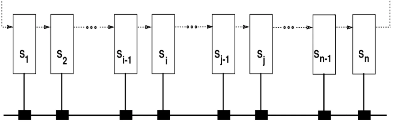
S1 S2 Si-1 Si Sj-1 Sj Sn-1 Sn
Figure 3: Token-Bus network with identified groups
To thoroughly analyze the subset of scenarios resulting from the failure of a group of stations, let us consider the network presented in Fig 3. Between stations S2 and Si−1 there can be any number of stations, as well as betweenSi and Sj−1, and also betweenSj andSn−1. The following situations may then happen:
i) The failed group of stations is located at the ring edges, i.e. stations S1 to Si−1 or stations Si to Sn have failed. In both cases the solicit any procedure is performed by the active station with the lowest address. This means that all the presumable responders will have addresses above thesolicit successor senderand therefore they will delay theirset successorframe transmissions until the second window. The process ends with the election of the non-failed station with the highest address as the new successor, for the current token holder.
ii) The failed group of stations is far from the ring edges, i.e. stationsSi up to Sj−1 have failed. The solicit any procedure is started when station Si−1 is trying to pass the token. In this case, stations with addresses above and below thesolicit successor senderare simultaneously present. Stations with addresses below thesolicit successor senderrespond in the first window and the one with the highest address is chosen, i.e. stationSj, which was the successor of the last failed station.
14Thefloorfunctionbxcis defined as the greatest integer not greater thanx.
iii) The recovery process is initiated by the highest address station, i.e. stationsS2up toSi−1 have failed.
In this case all the stations in the network, whether failed or not, have addresses below the solicit successor sender. Responses to thesolicit anyquery are all issued in the first window. The process is won by the highest address responder (Si in the given example), i.e. by the successor of the last failed station, in the former logical ring.
iv) The failed group of stations immediately precedes the lowest address station, i.e. stations Sj up to Sn−1 have failed. Thesolicit any procedureis started when station Sj−1 is about to pass the token.
In this case, there will be only one station in the network with its address below thesolicit successor sender. Contention is avoided and in consequence, logical ring restoration will be performed very fast.
Therefore, this situation corresponds to the best case scenario of station group failure.
The time spent in the recovery process just described – which does not present disturbing effects, like the appearance of passed over or skipped stations – is given by equation (22). In this equationtrcp represents the duration of an eventual contention process, as given by equation (3).
tina←gf ail=tSD+ 2.(tT K+tW F) + 10. tSlot+tSS2+trcp (22) In the worst-case, the recovery of the logical ring for a single failed group of stations can last as long as:
twcina←gf ail=tSD+ 2.(tT K+tW F) + 10. tSlot+tSS2+twcrcp (23) The best case scenario only occurs when the lowest addressed station immediately follows the last failed station, as previously mentioned. The inaccessibility time is obtained directly from equation (22), makingtrcp =tSSF.
S1 S2 S3 S4 S5 S6 S7
Failed Station
Figure 4: Example of a multi-group failure scenario
Multiple Failed Groups
It is now time to generalize our previous results on multiple failures, by allowing the existence of several groups of failed stations. In this case, the overall inaccessibility time can be obtained directly from the previous results on the single group failure, through its multiplication by the number of failed groups (Ngf ail):
tina←mgf ail =Ngf ail. tina←gf ail (24) When all the failed groups have the same number of stations, i.e. the same group dimension (Gfdim), equation (24) can be written in the form:
tina←mgf ail =
Nst
Gfdim+ 1
. tina←gf ail (25)
The worst-case scenario is obtained with the highest possible number of failed groups, which for a given set of active stations occurs when all the failed groups present the same minimum dimension, i.e. Gfdim= 2.
twcina←mgf ail = Nst
3
. twcina←gf ail (26)
Token-Bus Analytic Results
In order to complete our study of networking accessibility we now evaluate the inaccessibility time bounds, for a given Token-Bus network, for example, an industrial environment with a small cell network for real-time manufacturing control. The network length Cl = 500m and the total number of stations NST = 32. The results of the evaluation, for each one of the studied scenarios, are summarized in Table 3.
Data Rate -5M bps
tSD tSlot Scenario tina(ms)
(µs) (µs) min. max.
No Joins 0.073 0.100
Station Join No Contention 0.118 0.145 Contention 0.382 4.612 Multiple Joins (NST = 32) 0.363 139.999
Station Leave 0.056
11 27 Multiple Leaves (Nst= 32) 0.112 1.674
No Successor 0.306
Token Loss 1.717 5.794
Multiple Fails (Nst = 32) 0.612 4.896
Station Group Fail 0.521 5.176
Multiple Group Fails (Nst= 32) 5.697 51.762 Data Rate - 10M bps
tSD tSlot Scenario tina(ms)
(µs) (µs) min. max.
No Joins 0.086 0.133
Station Join No Contention 0.108 0.155 Contention 0.508 5.605 Multiple Joins (NST = 32) 0.396 162.821
Station Leave 0.043
21 47 Multiple Leaves (Nst= 32) 0.087 1.302
No Successor 0.336
Token Loss 1.897 8.994
Multiple Fails (Nst = 32) 0.672 5.376
Station Group Fail 0.611 6.289
Multiple Group Fails (Nst= 32) 6.900 62.886
Table 3: Token-Bus Inaccessibility Times (ladd= 48)
The worst case figures are quite high, like for example 140msfor the multiple joins case in the 5M bps bus. However, note that some of the situations either: occur only during start-up of the network; station configuration; or (in certain settings) allow more restrictive assumptions about multiple failures. This brings the highest figures drastically down, as shown in [41].
4 Case Study: Token-Ring
The ISO 8802/5 Token-Ring is a local area network that uses a token-passing access method over a ring architecture. Individual stations attach to the network through the use ofconcentrators, imposing astar topology over the bare ring architecture [44].
Access control uses a token passing protocol. Access to the shared broadcast medium for data transmission is only granted to the station which currently holds the token. A token priority reservation scheme is used to schedule message transmissions accordingly their urgency.
The performance of token-ring access method has been studied along the last decade by a set of authors [2, 35, 36, 45]. Although these studies neglect the influence of inaccessibility, by considering that the network always operate normally, an exploratory analysis on the performance of token-ring error handling mechanisms has been provided in [48]. However, it is essentially biased by an experimental evaluation of key error scenarios in a specific network configuration, being hard to infer absolute performance figures in other network configurations.
Our approach is substantially different: we made an exhaustive quantitative analysis of the 8802/5 error handling mechanisms, deriving a set of easy-to-use formulas that can be used to predict the inaccessibility times on any network configuration.
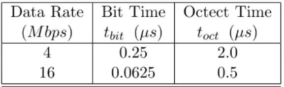
Data Rate Bit Time Octect Time (M bps) tbit (µs) toct (µs)
4 0.25 2.0
16 0.0625 0.5
Table 4: Parameters for an ISO 8802/5 Token-Ring LAN
Network Characterization
For our purposes, two important parameters characterize the basic operation of any ISO 8802/5 Token-Ring network:
Data Rate - The rate of data signalling, in the ring. It gives a meaning to thebit and octect times.
Network Ring Latency- This parameter accounts the time required for a data unit to propagate once around the ring. It is an aggregate variable accounting for station delays and network size, as expressed by equation:
trlat=tP D+tbit.(NST . latst+latAM) (27)
• tP D – End-to-end ring cable propagation delay. It is a ring length-dependent variable with a typical value of 5µs/km.
• latst – Station latency, i.e. the delay expressed in bits that each individual station introduces in the circulation of data units.
• latAM – Depth of the Active Monitor latency buffer, in bits. The extra delay, introduced by this station, aims two goals: assure a minimum latency on the ring that allows token circulation and provide phase jitter compensation [47].
• NST – Maximum number of stations in the network. Equation (27) defines therefore a worst-case bound for the ring latency instead of their current value. However, notice that its variation can usually be neglected for small variations on the number of ring active stations.
MAC Protocol Data Units
Several types of protocol data frames are exchanged between peer MAC15 entities to perform the following functions:
– Purge the ring of frame remnants.
– Elect a new active monitor.
– Delimit a failure domain.
– Report the presence of an active monitor on the ring.
– Support of theneighbor notification process16.
– Detect the presence of stations with duplicated addresses.
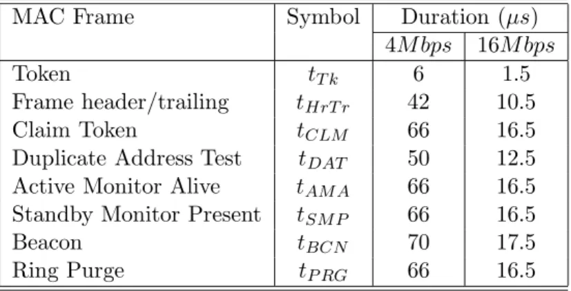
MAC Frame Symbol Duration (µs)
4M bps 16M bps
Token tT k 6 1.5
Frame header/trailing tHrT r 42 10.5
Claim Token tCLM 66 16.5
Duplicate Address Test tDAT 50 12.5 Active Monitor Alive tAM A 66 16.5 Standby Monitor Present tSM P 66 16.5
Beacon tBCN 70 17.5
Ring Purge tP RG 66 16.5
Table 5: Duration of MAC Token-Ring Protocol Data Units (ladd= 48)
MAC Timer Symbol Evaluating Default
Expression Values
Return to Repeat tT RR 4.1ms
Holding Token tT HT 10ms
Queue PDU tT QP 10ms
Valid Transmission tT V X tT RR+tT HT 10ms No Token tT N T tT RR+Nmax. tT HT 1s
Contention Monitor tT CM 1s
Active Monitor tT AM 7s
Standby Monitor tT SM 15s
Unresolved Beacon tT U B 26s
Table 6: MAC Protocol Timers
The duration of all standard MAC protocol frames which take part in these actions are pre- sented in Table 5, for an address length (ladd) of 48 bits. The values were computed based on frame length and data rate.
15Medium Access Control.
16This process aims to provide each station with the address of its nearest upstream neighbor, required for failure domain delimitation. Additional details on neighbor notification can be found in [20].
MAC Protocol Timers
A set of timers are used by the standard MAC protocol either to detect the abnormal absence of given actions/events or to control the duration/interleaving of others. These timers are listed in Table 6 together with the default values used in the token-ring implementation provided by [47].
Specific timers –contention monitorand unresolved beacon – used by [47] are also included in the table, although not defined in the standard specification.
Token-Ring Accessibility Constrains
A comprehensive set of scenarios leading to network inaccessibility will be analysed in this section. As a general rule, we start with very simple single error situations that in many cases degenerate into more complex scenarios. Additionally the analysed scenarios progressively evolve to less restrictive – and thus more realistic – operating conditions/fault assumptions. For most of the cases, the main analysis is completely general, being particularised for best and worst cases, afterwards.
Stripping Errors
Before transmitting any queued frame into the network a station must wait for the reception of a free token. Should the priority of queued frames be equal or greater than the priority of the received token and they will be elected for transmission. Frame transmission is initiated by setting thetoken bit in the receivedaccess control field and by clearing the correspondingmonitor and priority reservation17 bits. The remaining frame control fields, data and ending sequence are appended afterwards.
After completing the transmission of the last queued frame or when there is not enough time remaining inTimer:Holding Token(THT) to finish the next transmission, the emitting station will start to send “fill symbols”. A new free token is generated upon the reception of a frame with a source address matching its own address, but the station will continue to send “fill symbols”
until the last transmitted frame is received18 or until the expiration of Timer:Return to Repeat 19 (TRR). In normal operation, this action strips out from the ring all the frames that a station has transmitted. Should the station fail before removing from the ring the transmitted frames, and these would tend to persist in circulating through the ring if appropriate recovery mechanisms were not provided.
A similar error scenario occurs when a station that has issued a priority tokenfails before it is able to restore the former ring service priority, as specified in [20]. In this circumstance, priority tokens would also tend to persist on the ring.
The presence ofcirculating framesorcirculating priority tokenson the network ring is prevented through a dedicated active monitor mechanism. The time required for the elimination of these packets results from the sum of two distinct contributions: the time needed for error detection plus the time required for its recovery, as described by equation (28).
tina←nostrip =tdect←nostrip+tprp (28) In order to detect the presence of persistent data units on the ring, the active monitor marks every passing frame or priority token, by setting the correspondingmonitor bit. Any frame or token arriving at the active monitor with itsmonitor bit set is stripped from the ring, by this station.
17Frames are always transmitted with the priority of the received token, regardless their own priority.
18Identified by the non-assertion of theintermediate bitin theending delimiterfield.
19This timer has been re-started upon transmission of the last frame.
S1
S2
S3 S4
S5 S6
wiring concentrator active monitor
Figure 5: Example of a token-ring network
Error detection can never be performed in a time lower than the network ring latency and its exact value depends on the failed station and active monitor relative locations. In the best-case the active monitor immediately follows the station originating the error whereas in the worst-case the same station immediately precedes the active monitor. This means that both situations differ at most in one ring latency period, as described by equation (29).
tdect←nostrip=
trlat best-case scenario 2. trlat worst-case scenario
(29) Upon error detection, the active monitor initiates a recovery procedure that is started with the continuous transmission of ring purge frames. Once the active monitor detects the reception of one of its own ring purge frames, it starts to transmit “fill symbols” during a period given by tT RR, to ensure that all these protocol data units have been stripped from the ring and generates a
“new token” afterwards. Thispurge ring process– tprp – terminates timely, in the absence of other network errors, with a best-case duration given by:
tbcprp=tprP rg+tP RG+trlat+tT RR+tprT k (30) wheretprP rgandtprT k represent the processing overheads required to generate thering purgeframe and the token, respectively. The designation processing overhead, herein employed, is essentially due to a particular token-ring implementation [47] where media access protocols are executed in a special-purpose LAN communications processor. With such an architecture it is reasonable assume that generation of MAC frames and tokens may be affected by some latency and therefore we consider worst-case figures, in the processing overheads, for the derivation of an expression that, in the absence of other network errors, gives the worst-case duration of thepurge ring process:
twcprp=twcprP rg+tP RG+trlat+tT RR+twcprT k (31) Expressions for the best and worst inaccessibility durations, due to the absence of ring stripping can be easily derived. These durations, that we signal with superscripts bc and wc, are given by equations (32) and (33).
tbcina←nostrip= 2. trlat+tprP rg+tP RG+tT RR+tprT k (32) twcina←nostrip= 3. trlat+twcprP rg+tP RG+tT RR+twcprT k (33) Let us now analyse some side effects that token regeneration, by the active monitor, may have on the normal token circulation. Consider the token-ring network pictured in Fig. 5. StationS5 is either the then-current token holder or thepriority tokenremover when it fails, while station S1 is the then-current active monitor. StationS6 which was about to receive the token, when the failure of its upstream station, is passed over. So, in addition to the time required for token regeneration, stationS6must wait an extra token rotation to get access to the network. This means that different stations in the network may have a different view of inaccessibility and that, as a general rule, the inaccessibility time may not be merely represented by the raw inaccessibility duration. It must be consolidated with the addition of the network access delay upper-bound.
Bit Corruption Errors
Let us proceed our analysis of token-ring inaccessibility by considering a scenario where some selected bits, inside the frame stream, see their values modified due to the occurrence of faults.
Although corruption of individual bits is not likely to happen, this analysis is important because it evidences relevant aspects of protocol robustness.
For example, in 8802/5 frames a set of very important control bits are transmitted outside the FCS coverage domain, due to the need of their “on-fly” modification by the MAC protocol, and it is important to understand how the corruption of these and other equally relevant bits can affect ring operation. This scenario provides a systematic analysis of the possible bit corruption errors.
• Access Control Field– The following set of bits are defined within this field:
Priority and reservation bits– Corruption of priority and reservation bits can affect both frames and tokens, and they can eventually lead to the issuing of a token with a priority either higher or lower than the correct. In Table 7 we provide a systematic view of the possible error conditions. Errors due to incorrectpriority bits are more severe than those resulting from the corruption ofreservation bits since they escape from the control of the priority reservationscheme20. Its recovery is performed either through anactive monitor strippingaction or through a dedicatederror recovery procedurethat clears the priority stacks [20]. Errors resulting from reservation bits corruption are recovered strictly by the intervention of thepriority reservationmechanisms.
Monitor bit– This bit is always originally transmitted with a zero value. Its eventual corruption may lead to the premature removal of the frame or priority token from the ring, through the aforementionedactive monitor strippingaction.
Token bit– The setting of this bit, by corruption, can transform afree tokeninto abusy tokenthat will be later eliminated through an active monitor strippingaction. On the other hand, the incorrect clearing of thetoken bit converts a frame into an incorrectly formed token. Such a scenario will be studied ahead.
• Frame Body– The frame body is protected by FCS checking and consequently, a corruption in this stream will be detected with the coverage provided by the associated CRC mechanism.
Frames with CRC errors will be usually discarded by the MAC sub-layer and, exception made for the eventual corruption of the source address field, they do not normally lead to network inaccessibility. Source address recognition is a mandatory condition for token release, by the then-current holding station, and the lack of such event leads to a token loss scenario, to be
20Additional details on priority reservation can be found in [20].