Changing the throughput thresholds has the most impact on the percentage of users that perform handovers, and therefore on the system's profitability. The motivational framework for this study is also presented, as well as a description of the work structure.
Overview
Today, life is generally much more stressful than it used to be for many reasons. Smooth browsing and video streaming, on the other hand, lead to an increase in the same NPS.
![Figure 1.2 - Global mobile devices or connections (extracted from [4]).](https://thumb-eu.123doks.com/thumbv2/123dok_br/19768907.0/25.892.135.682.105.367/figure-1-2-global-mobile-devices-connections-extracted.webp)
Motivation and Contents
A complete description of the developed model, as well as the simulator that implements it, is given in Chapter 3. Last but not least, Appendix D provides the user's manual to assist in using the simulator.
Network architecture
PCRF – The Policy Control and Charging Rules function is responsible for deciding on policy control and for controlling the charging functionalities in the P-GW. HSS – The Home Subscriber Server that stores user subscription information, determines a user's identity and rights, and tracks activity through the Authorization, Authentication and Accounting (AAA) server, and enforces cost and QoS policies through PCRF.
Radio interface
MME - Mobility Management Entity is the control node that processes signaling between UE and CN and is responsible for managing security functions (authentication, authorization for both signaling and user data), handling of idle state mobility , roaming and deliveries. The third scenario is the most used by operators, as it allows CC to be distributed across different bands.
![Figure 2.2 - Type 1 frame structure (extracted from [13]).](https://thumb-eu.123doks.com/thumbv2/123dok_br/19768907.0/32.892.260.634.385.748/figure-2-2-type-frame-structure-extracted-13.webp)
Coverage and capacity
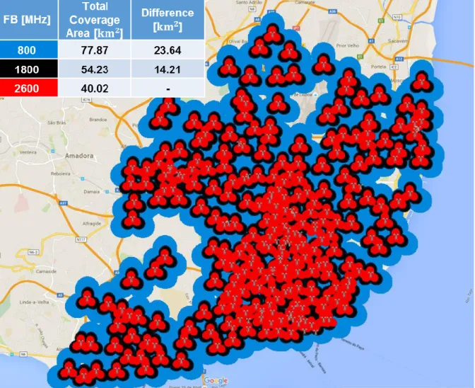
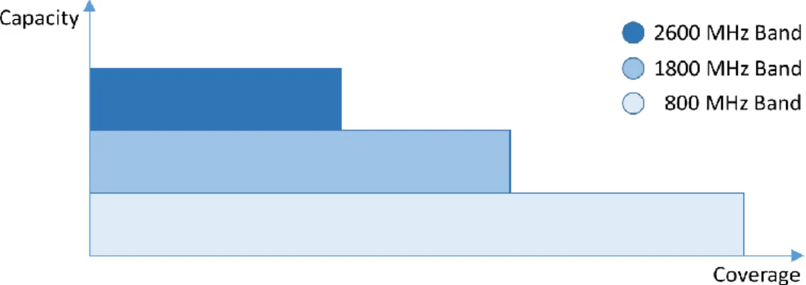
Different frequency bands lead to different path losses and consequently different coverage areas, as shown in Figure 2.5. Also, higher frequency bands afford higher capacity due to the bandwidth allocation as described in Table 2.2.
Services and applications
Guaranteed Bit Rate (GBR) identifies that a bearer has a permanently allocated minimum resource, e.g. an access control function in the eNodeB. Aggregated Maximum Bit Rate (AMBR), which indicates the aggregate maximum bit rate that a UE can have for all carriers in the same PDN connection.
![Table 2.6 – QoS service classes (adapted from [36]).](https://thumb-eu.123doks.com/thumbv2/123dok_br/19768907.0/38.892.108.794.464.646/table-2-qos-service-classes-adapted-from-36.webp)
Inter-frequency Handover
Inter-frequency load balancing is controlled by the cell reselection procedure; if the UE finds a cell outside its tracking area, a location registration must be performed. Since system parameters and radio resource preferences are transmitted to the UE using System Information Blocks (SIBs), it is possible for an eNB to force a user in a cell edge to select the one with the highest transmitted power, or force an HO to another provider with more resources available, [8], [20].
State of the art
In the case of a larger penalty factor, the algorithm chooses to reduce the number of HOs, at the expense of the larger average queuing backlog, resulting in a larger average system delay. Different penalty factors were tested, and it was concluded that the minimum value of the worst queue is reached when the penalty factor is 0.05. To deal with this problem, [52] introduced a load-based handover threshold depending on the load of the neighboring cells by means of a tuning step as illustrated in Figure 2.8.
The proposed handover algorithm distributes the load of congested sectors among other sectors, thereby eliminating congestion. Similar to [50], the performance of the proposed algorithm is compared with vertical handover algorithms based on SINR and load balancing.
![Figure 2.7 - Comparison of normalised throughput and worst-case queue backlog (extracted from [7])](https://thumb-eu.123doks.com/thumbv2/123dok_br/19768907.0/43.892.271.620.454.719/figure-comparison-normalised-throughput-worst-queue-backlog-extracted.webp)
Model Description
Due to the omission of the secondary lobe, as shown in Figure 3.1, the front-to-back attenuation must have a high value. The total throughput of the network (𝑅𝑏,𝑡𝑜𝑡𝑎𝑙) is equal to the sum of the offered bit rate for all users. The service profile is given by the number of active users in a particular service in the system.
The percentage of IFHO users per service (𝑝𝑈,𝐻𝑂[%]) results from dividing the number of HOs (𝑁𝑢,𝐻𝑂,𝑠) by the number of active users of that service. In common sense, an increase in the throughput of the system leads to an increase in user satisfaction, and in turn revenue to the operator; however, this is not necessarily true.
Algorithms
- RBs Calculation
- Reduce Load of Sectors
- Load Balancing via Inter-Frequency Handovers
- Try to Allocate Delayed Users
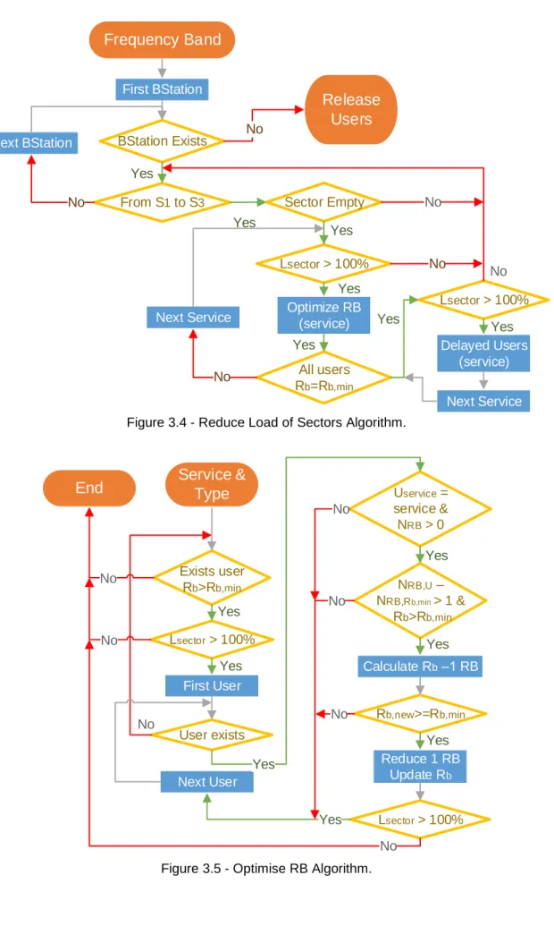
In the first step, one RB is reduced to the user that has a throughput higher than average, and then the load of the sector is checked, as described in Figure 3.5. The algorithm described in Figure 3.7 has as inputs the FB that HO UEs will use (𝐹𝐵𝑖) and the FB that receives these UEs (𝐹𝐵𝑜). If so, it calculates the number of RB that 𝑈𝑖 will use to be served with 𝑅𝑏,𝑎𝑣𝑔 in 𝑆𝑜.
After that and if this number of RB is not available at 𝑆𝑜, the process will continue to another sector and so on and so far. The algorithm described as "Find User HO" is shown in Figure 3.8, where the search depends on the type, 1 to search for users subject to IFHO and 2 to search for users to be reduced in 𝑆𝑜.
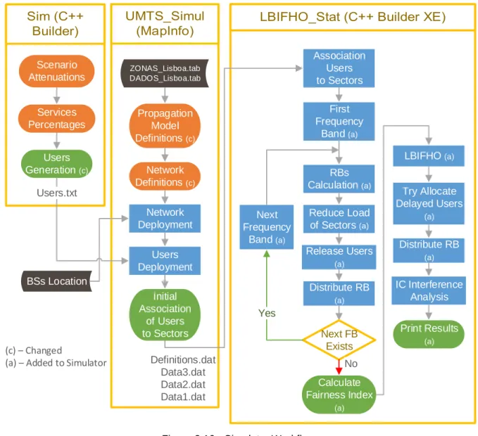
Model Implementation
After this, the process is very similar to the one presented in LBIFHO, but this time it will be redistributed instead of the user suffering from HO. After entering all antenna parameters, propagation model and BS location, the coverage area for each of the frequency bands is calculated. Taking into account the different population density in the districts of a city, some sectors may be overloaded, which means that a reduction must be made to be in line with the system capacity.
Finally, the Try Allocate Delayed Users algorithm will take place, and as the name suggests, this algorithm checks if it can reassign any of the delayed users in the network. It should be noted that IC interference analysis is available in the simulator, but as interference analysis was beyond the scope of this thesis, it was decided to keep it disabled.
Model Assessment
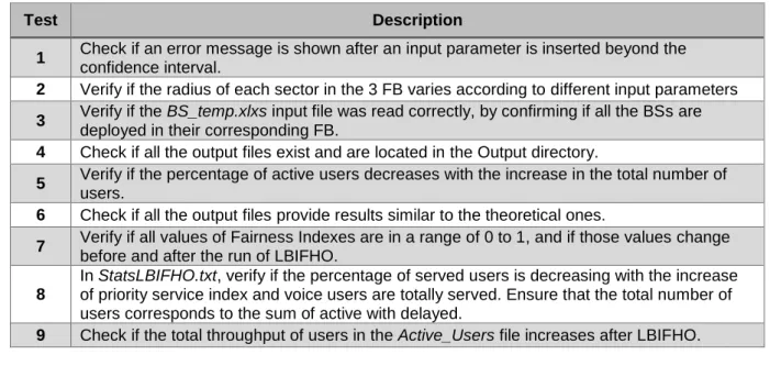
5 Verify if the percentage of active users decreases with the increase in the total number of users. Make sure the total number of users matches the sum of active with delayed. Based on all the algorithms described previously, the percentage of active users is expected to decrease with the increase of the total number of users (user density).
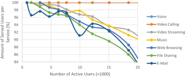
In order to check the accuracy of service priorities, several simulations have been made that vary the total number of users. The percentage of active users per service was expected to decrease more as the total number of users increased for the lower priority services, as evidenced in Figure 3.13 (voice overlapped with videophones).
Scenarios Description
The traffic mix is taken from [2], where the considered device is a smartphone, Table 4.2, video streaming occupying the majority of the resources, since today consumers'. In the reference scenario, one considered a 2x2 MIMO configuration and other parameters as shown in Table 4.4. The number of BS connected for each frequency band is presented in Table 4.5; it should be noted that each BS has three sectors (all of them are connected).
It should be noted that intercellular interference is not analyzed in the reference scenario, for the reasons described in section 3.3. As a first analysis, the impact of different network loads is studied, varying the total number of users from 1 000 to 25 000, where there is a higher concentration of simulations at lower numbers due to increased simulation time.
![Table 4.2 – Services characteristics (adapted from [2], [37] and [38]).](https://thumb-eu.123doks.com/thumbv2/123dok_br/19768907.0/69.892.109.792.424.642/table-4-2-services-characteristics-adapted-37-38.webp)
Analysis on the Number of Users
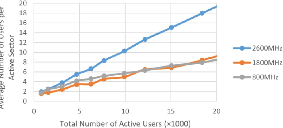
On the other hand, the increase in the number of users in the network means that the population density will also increase, therefore, leading to a decrease in the average throughput per service. On the other hand, voice services, video phones and music services remain roughly the same, despite the increase in the number of active users. This increase in the number of users can also be translated into an increase in the load of the sectors, as can be seen in Figure 4.5 and Figure 4.6.
If the user is at the cell edge (at a distance greater than 2/3 of the radius of that FB) and the number of RBs used for the average throughput of that service is higher than in the destination FB. The results show that the average fairness index decreases with the increase in the number of users.
Low Load Analysis
- User and traffic profile
- Bandwidth Analysis
- Impact of Throughput Thresholds Analysis
- Services Percentages Analysis
The high values of standard deviation are due to the low number of users in the system and the randomness of their generation. As mentioned before, the number of HOs is supposed to be different according to the test, since the throughput thresholds (low and high) are one of the factors of HO decision, Figure 4.22. Reducing the HO decision interval results not only in an increase in the number of HOs, but also in 0.
This increase indicates that the higher the load per sector, the higher the percentage of HO in the 2 600 to 1 800 MHz pair; this fact is further demonstrated in Section 4.4.3. The overall network throughput presented in Figure 4.31 also follows the expected higher gain behavior in the video-centric scenario, while the voice-centric scenario remains the same.
High Load Analysis
Bandwidth Analysis
In contrast to the low load, in the high load scenario the percentage of users served increases with the available bandwidth, as confirmed in Figure 4.32. Consequently, and since the number of covered users remains the same throughout all simulations, it is expected that the average load per sector decreases with increasing bandwidth, Figure 4.33. Analyzing Figure 4.35, it can be seen that video calling is the service that, in terms of fairness, gains the most with load balancing, but the same is not true for all others (except voice); voice users do not suffer from HO, their throughput remains the same after applying load balancing.
Regarding the number of reallocated users, one can see in Figure 4.36 that it decreases with the increase in the total bandwidth. Consequently, it can be concluded that if the reference scenario uses a higher bandwidth, the gain presented in Figure 4.11 also saturates at a higher value.
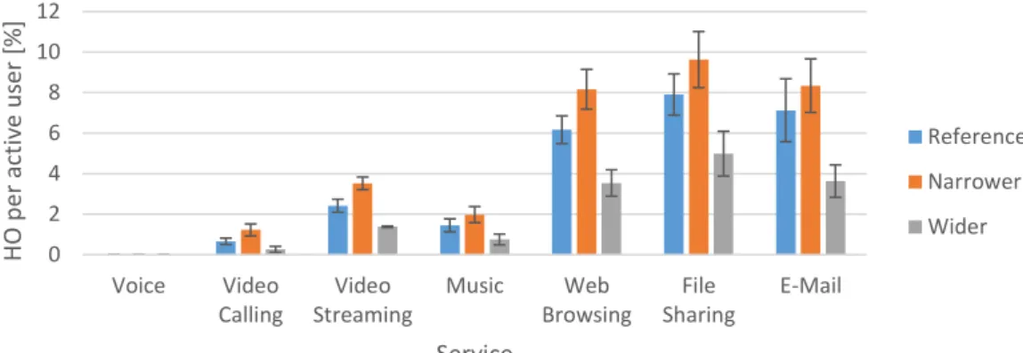
Impact of Throughput Thresholds Analysis
To better understand the results, Table 4.16 presents the variation in the percentage of HOs, taking into account the variation in throughput thresholds of the reference scenario. The more congested the network, the higher the percentage of transfers in the 2 600 to 1 800 MHz pair. This efficient exploitation of resources in the network leads to an increase in overall throughput in the voice-centric scenario, as illustrated in Figure 4.49.
This chapter summarizes the work done in the thesis and the main conclusions are presented. The same is not the case with the average load per sector, which decreases as the available bandwidth increases. High load conditions bring some variation in the percentage of users served for different service profiles, where video centric serves only 93.8% of the total users covered, while voice centric reaches 98.8%.
In fact, associated with these conditions is a congested network in a video-centric scenario.
Services Percentages Analysis
![Figure 1.3 - Comparison of cognitive load under different stressful situations (extracted from [5])](https://thumb-eu.123doks.com/thumbv2/123dok_br/19768907.0/25.892.115.786.712.1013/figure-comparison-cognitive-load-different-stressful-situations-extracted.webp)
![Table 2.2 – Allocated spectrum and the total price paid by the operators. (extracted from [26], [27])](https://thumb-eu.123doks.com/thumbv2/123dok_br/19768907.0/34.892.171.728.168.433/table-allocated-spectrum-total-price-paid-operators-extracted.webp)
![Figure 2.8 - Tuning of traffic reason threshold with 4% step (extracted from [52]).](https://thumb-eu.123doks.com/thumbv2/123dok_br/19768907.0/44.892.293.600.115.388/figure-tuning-traffic-reason-threshold-step-extracted-52.webp)