First of all, I would like to give special thanks to Professor Jo ˜ao Henriques for his patience and for introducing me to the subject of improving hydrofoil boats. I would like to express my appreciation to Professor Virginia Infante for the guidance and support throughout the work and for introducing me to the company Optimal Structural Solutions. The interface between the three components allows the user to generate a profile for the desired conditions.
Nomenclature
Acronyms
Introduction
- Motivation and objectives
- Structure of the thesis
- Introduction
- State of Art
- Methodology
- STRUCTURE OF THE THESIS 3 daggerboard’s structural improvement. The project conditions are described and summarized in order
- Daggerboard design
- Structural analysis
- Material analysis
- Conclusions
- Future work
The steps taken to develop this work and the project conditions for the new hydrofoil design are described in this chapter. An analysis of the material is done to find different solutions for the structure, aiming to reduce the cost. Mechanical parameters, as well as environmental conditions, are decided to select materials for the structure of the dagger.
State of Art
- C-Class catamaran racing boat
- DAGGERBOARD PROFILES 7
- Daggerboard profiles
- DAGGERBOARD PROFILES 9
- Hydrofoil design
- Eppler’s hydrofoil
- Hydrofoil characteristics
- HYDROFOIL DESIGN 13 these daggerboards is the variation of the angle of attack, with the changes of the sea currents and the
- HYDROFOIL DESIGN 15
- Cavitation
- Material evolution
- PROJECT CONDITIONS AND ASSUMPTIONS 21
- Project conditions and assumptions
For this, it was decided to change the way of controlling the angle of attack of the dagger board. The hydrofoil creates a lifting force, perpendicular to the flow direction, and a drag force, which has the same direction as the flow (Fig.2.8). Due to the change of the curvature, the values of lifting and pulling forces also change.
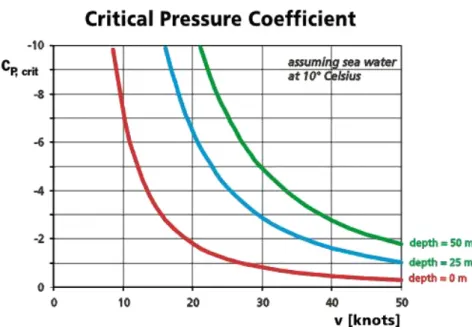
In Fig.2.12 a NACA 0012 is represented as thecpevolution with increasing the angle of attack. The only way to avoid cavitation, although it will never be completely avoided, is to generate balance between the angle of attack, the speed of the boat and the airfoil pressure coefficient. The design approach implemented on this work [19] was performed by setting the mass and speed of the boat.
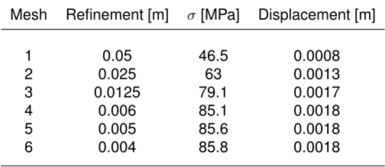
CorrespondentCL, produced by the optimized geometry, can be used to calculate the cross-sectional area of the hydrofoil Eq. A redesign of the structure was undertaken to improve the displacement results by maintaining a safety factor above that required by the Optimal company. Since a fluid dynamics analysis was not included in this study, it was not possible to provide the pressure distribution over the depth panel of the daggerboard.
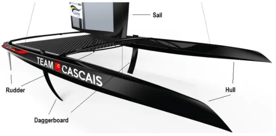
The first vessel built by Optimal had a mechanism that allowed the movement of the daggerboard through the hull.
![Figure 2.1: Team Cascais Catamaran [9].](https://thumb-eu.123doks.com/thumbv2/123dok_br/19765819.0/28.892.181.722.104.672/figure-2-1-team-cascais-catamaran-9.webp)
Daggerboard design
- Hydrofoil design
- Class-Shape-Transformation Method
- HYDROFOIL DESIGN 25
- Differential Evolution
- HYDROFOIL DESIGN 27 Mutation
- Hydrofoil Shape Generation
- HYDROFOIL DESIGN 29
- Case of Study
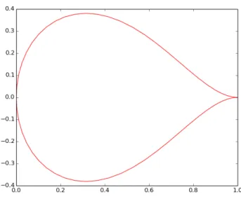
- CST shape
- HYDROFOIL DESIGN 31 Xfoil software performs analysis to the airfoils in viscous conditions by introducing the Reynolds
- Control coefficients
- HYDROFOIL DESIGN 33
- Objective Function
- HYDROFOIL DESIGN 35
The main goal of hydrofoil design comes from knowledge of boundary layer properties and the relationship between geometry and pressure distribution. Before using the CST method, it was necessary to define the x-coordinates of the hydrofoil. If the result of the objective function is reduced by this new vector, the vector remains and is used in the next generation (iteration).
If the result of the objective function is better than the objective vector, the vector is not replaced - a selection operation. In Figure 4.7, it is possible to visualize the pressure distribution only on the top surface, where the load of the container is distributed. The first attempt to define an objective function focused on the hydrofoil pressure distribution.
For this reason, it was decided to use the minimum profile pressure and maximize, Eq. The allowable pressure value must respect the equation. Several iterations were done varying the weight of the objective function. These were acceptable values as the pressure coefficient modulus remained below the cavitation number defined as 2.2846.
For the scenario presented in Tab. 4.1) the final form has the following characteristics of the hydrofoil, Tab.
![Figure 4.1: Bernstein polynomial decomposition [20].](https://thumb-eu.123doks.com/thumbv2/123dok_br/19765819.0/48.892.248.651.114.280/figure-4-1-bernstein-polynomial-decomposition-20.webp)
Structural Analysis
- Pre-study
- Static analysis - blade
- PRE-STUDY 39 Table 5.2: Stress and Maximum Displacement - Blades
- Modal analysis - blade
- Daggerboard’s analysis
- DAGGERBOARD’S ANALYSIS 41 daggerboard behaviour, a modal analysis was also performed
- Static analysis
- Modal analysis
- DAGGERBOARD’S ANALYSIS 43
- CST DAGGERBOARD IMPROVEMENT 45
- CST daggerboard improvement
- Structural designing
- Static analysis - improved CST daggerboard
- Modal analysis - improved CST daggerboard
- CST DAGGERBOARD IMPROVEMENT 49
Since the CST airfoil is thinner than the NACA airfoils, a higher blade displacement of the CST airfoil was expected. The final network, constraint and applied pressure are illustrated in Fig.5.6, Fig.5.7 and Fig.5.8 respectively. A modal analysis enabled the natural frequencies of the structure and the corresponding vibration modes to be obtained.
It is necessary to pay special attention to the graphic lecture of the time, since the range of natural frequencies in the NACA 2412 profile was higher than in the CSTinitial profile, the time obtained was also higher. While the NACA 2412 (Fig.5.13) moves in the positive x direction, the initial CST profile moves in the negative direction (Fig.5.14). Despite both having similar displacement paths, in the vertical direction, (Fig.5.15 and Fig.5.16) the initial CST profile tends to have a smaller movement amplitude.
This profile is able to distribute the load uniformly over the surface (Fig. 5.18) to obtain a more linear deformation of the structure compared to NACA 2412 (Fig. 5.17). With the weight and cross-sectional area defined, Eq. 5.3) the same aspect ratio (A) of original daggerboards is used, which is equal to 3. The stress distribution and total displacement of the structure are illustrated in Fig. respectively. 5.20 and Fig. 5.21.
The maximum verified stress was around 116 MPa, Figure 5.26, leading to an increase in the safety factor to 23.

Material analysis
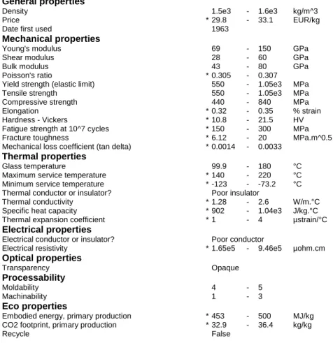
The development of high-performance composites is one of the major material developments of the past decades [18]. By crossing the information of each property requirement, the selected materials are shown in Tab.6.1. The carbon fiber reinforced composite (CFRP) offers more stiffness and strength and is also lighter than polyester-glass reinforced composite (GFRP), but the cost is higher.
Although a heavy material, it can be incorporated into a CFRP composite matrix to create a final material ideal for a dagger. Rigid polymer foam HD (RPF HD) and Rigid polymer foam MD (RPF MD) are materials with very low yield strength that develop a safety factor below the prescribed limit of 5. To verify the behavior of the daggerboard with these materials, a static analysis was performed for both CFRP as for titanium alloy, tab.6.2.
However, the composite CFRP and titanium alloy had a displacement of 34.6 mm and 43.1 mm, respectively, which was not a significant increase.

Conclusions
The material study was elaborated by defining the key mechanical properties to be maximized, minimizing the density and cost of the material. By conducting a structural analysis of the final sword with these new materials, it was concluded that the verified maximum displacement had not undergone any significant change. The main change to the structure concerned the total weight and cost of the sword for each material (Tab.6.2).
The main conclusion is that the T800 material should be chosen if the main goal was to increase the overall weight. On the other hand, if cost was the main concern, then the composite matrix of CFRP and titanium alloy should be considered for the daggerboard construction.
Future work
FUTURE WORK In addition to this daggerboard work, a hydrodynamic and aerodynamic study of the catamaran could be carried out, including the daggerboard material modification to understand if this change affects the boat's performance for the better or for the worse. In this work, it was concluded that the main advantage of using the two new materials, composite CFRP and Titanium alloy, is limited by the final price of the dagger board. However, if the new mechanical system is used on the new catamaran, where the daggerboard remains stationary, the sailors do not need to move it during the race, which makes no difference if the daggerboard is heavy.
Since there is no weight limit in the rules for the boat, a study of the whole boat will be done to quantify how the weight difference affects the catamaran's performance. Finally, the daggerboard and rudder interaction must also be analyzed to understand their influence on each other. This study is important to understand how much the rudder configuration affects the daggerboard's performance and vice versa.
Bibliography
Alpha and rocker - two design approaches that led to a successful challenge for the 2007 c-class international catamaran championship. Institute of Physics, Publishing, Measurement Science and Technology.
Appendix A
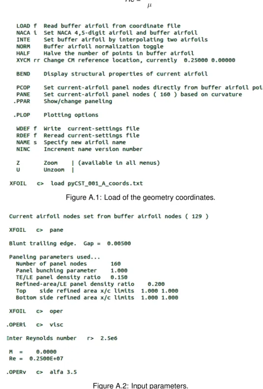
Xfoil software
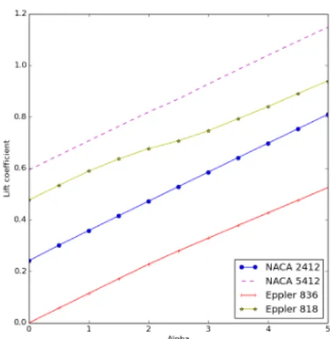
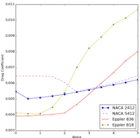
The polar, with the angle of attack, lift and drag coefficients and additional information is presented in fig. In most cases, convergence cannot be achieved due to boundary layer separation and stall regions. For this work, it is specified the hydrofoil coordinates, introduced in Xfoil software that performed a viscous analysis with a specific alpha.
In the interaction between Xfoil and the optimized program, several iterations are performed until the lift-drag ratio given by xfoil reaches the maximum value allowed by the geometry. It is possible to get information about the pressure distribution by graphical interface and by coordinates. This information is implemented in Ansys software to create a pressure distribution over the daggerboard to study the loading effects over the structure.
As can be concluded, this software is very useful for carrying out this type of study, allowing the calculation of the main characteristics of the hydrofoil in a fast and reliable way.
Appendix B
Structural analysis - complementary
- Blade
- Daggerboard
- DAGGERBOARD 7
- ORIGINAL L DAGGERBOARD 9
- Original L daggerboard
Since the original swashplate uses the NACA 2412 airfoil, only the modal results from this swashplate are presented and compared to the results from the CST swashplate. The aspect ratio and the relationship between the major and minor chords presented in subsection 5.3.1 are obtained from the original structure shown in Figure B.9. The major chord from the original daggerboard is equal to 0.225m, and the minor chord is 0.112m.
The relationship between the two is represented in Eq. B.1) and is used to calculate the new chord length for the new CST daggerboard.
Appendix C
Material Complement
Daggerboard with different materials
MATERIAL DATA SHEETS 13
Material data sheets
T800H DATA SHEET
TECHNICAL DATA SHEET
MATERIAL DATA SHEETS 15
The information presented on this data sheet was obtained by Firehole Technologies Inc., www.fireholetech.com, from various sources. However, IDES and Firehole accept no responsibility for the data values and strongly encourage data points to be validated with final material selection. This number was found on the product data sheet titled "Torayca T800H," Toray Composites (America) Inc., Santa Ana, CA.
Carbon fiber reinforced composites (CFRPs) provide greater stiffness and strength than any other type, but they are significantly more expensive than GFRP (see record). The fibers carry the mechanical loads, while the matrix material transfers loads to the fibers and provides ductility and toughness and protects the fibers from damage caused by handling or the environment.
MATERIAL DATA SHEETS 17
Titanium alloys can be used at temperatures up to 500 C - compressor blades of aircraft turbines are made from them. The alloy Ti 6%Al 4% V is used in quantities that exceed those of all other titanium alloys combined.

MATERIAL DATA SHEETS 19
![Figure 2.7: Forces Involved - V Profile [10]](https://thumb-eu.123doks.com/thumbv2/123dok_br/19765819.0/32.892.272.617.743.1029/figure-2-7-forces-involved-v-profile-10.webp)
![Figure 2.8: Airfoil’ forces [24]](https://thumb-eu.123doks.com/thumbv2/123dok_br/19765819.0/34.892.218.680.822.1090/figure-2-8-airfoil-forces-24.webp)
![Fig. 2.14 illustrates those three stages. Using the description of cavitation by [23], If the pressure above the liquid is reduced by any means, evaporation recommences until a new balance is reached](https://thumb-eu.123doks.com/thumbv2/123dok_br/19765819.0/38.892.217.680.760.1074/illustrates-description-cavitation-pressure-reduced-evaporation-recommences-balance.webp)
![Figure 4.2: Two-dimensional cost function showing its contour lines and the process for generating [33].](https://thumb-eu.123doks.com/thumbv2/123dok_br/19765819.0/49.892.286.624.387.625/figure-dimensional-function-showing-contour-lines-process-generating.webp)