One of the essential differences between humanity and other animals is the ability to communicate. The development of the capacity and coverage of mobile networks was gradual, and the generations were defined by a set of prerequisites. In addition, Massive MIMO extends the performance of a wireless connection by using multiple antennas.
Due to the distributed characteristic of the existing mobile network, the implementation of interference coordination and spatial diversity between base stations is very expensive. One of the expected features of the next generation fronthaul is the use of existing layer.
Objectives
This strategy should provide the benefits of statistical multiplexing provided by a packet network, along with the reuse of existing infrastructure. This infrastructure was used, for example, to evaluate the LTE signal compression of [11] and the transport of compressed IQ signals. Additionally, the analog signal is fed to a signal analyzer to evaluate the signal's quality metrics.
Dissertation Outline
This work presents a testbed implementation for Ethernet-based fronthaul, along with the challenges and solutions for providing reliable fronthaul transport over Ethernet infrastructure. Finally, an overview of the signal compression technique implemented in this work is shown in Section 2.3. Then, the VHDL implementation of the compression algorithm is detailed in Section 3.2, together with the developed blocks and its engineering solutions.
Fronthaul
Fronthaul Concepts and Existing Technologies
- Common Public Radio Interface (CPRI)
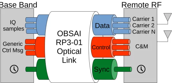
- Open Base Station Architecture Initiative (OBSAI)
- Open Radio Equipment Interface (ORI)
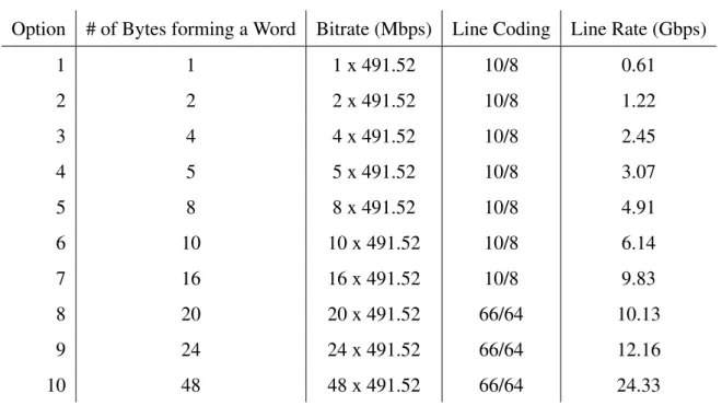
The BF is internally divided into 16 words, as shown in Figure 2.3, the bit width of these words is changed with the line rate option. For example, in line rate option 1, the bit width of each word is 8 bits, while in line rate option 2, each word carries 16 bits. Note that the IQ samples of Figure 2.3 do not necessarily use an integer number of words from the data block.
There is a nomenclature used to indicate the position of each bit in the CPRI stream. Also in the control and management domain, the specification defines software and configuration abstractions that are not covered by CPRI. The protocol also specifies how the compressed stream should be mapped in the IQ data space.
This software abstraction makes it possible to make changes to the RE without directly changing the REC. In the CPRI specification, the 256 control words are grouped into groups of four, called control subchannels. The purpose of each of the 64 subchannels is predefined in the CPRI specification, as shown in Figure 2.8.
Using a full stack allows other well-known protocols to be used in the ORI link.

Next Generation Fronthaul Interface (NGFI)
- Packet-Based Fronthaul
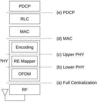
- Functional Split between BBU and RRU
16 the objective of next-generation fronthaul is to enable centralization of the radio access network and reduce network deployment costs. In this scenario, the fronthaul must connect several coordinated radio units to the central processing BS. In addition, the use of dedicated optical links to transport front-end information increases the overall cost of the network.
And finally, Section 2.3 shows how signal compression can reduce the bit rate requirement of the fronthaul. As previously discussed, the existing fronthaul uses dedicated optical links due to the strict requirements of the fronthaul specification. There are two ways to think about adapting the fronthaul to packet-based networking.
In this scenario, the fronthaul must implement techniques to overcome the Ethernet truncations, and provide the fronthaul transport even on imperfect Ethernet network. On the other hand, the fronthaul required to achieve this goal has very high requirements, which increases the overall cost of the fronthaul network. In this scenario, the bandwidth usage on the fronthaul is slightly lower than the previously shown scenario (d).
In an existing network, this mapping is static and realized in the network configuration, but fronthaul can enable a more flexible mapping.
Fronthaul’s Signal Compression
- PUSQH Compression Algorithm
In fact, these dynamic topology changes can benefit even more from the tidal wave effect in the network usage. Step 23 is to remove the cyclic prefix from the OFDM signal creating the signalx[n], where0≤n <. For example, the Levinson-Durbin algorithm uses the autocorrelation information of a signal to derive an FIR filter that can predict the next samples under certain error, based on a linear combination of the previous samples.
Such a strategy is commonly used in the compression of audio and video and was shown by [11] to be adapted for LTE signals as well. This technique also takes advantage of the statistical characteristics of the error signal, since the probability distribution of the quantized error is approximately Gaussian. One of the main advantages of the PUSQH algorithm is the low use of computer resources.
Although the training phase of the prediction filter may use some computational resources, this phase can be performed offline. In fact, the application of the prediction filter has very low cost, since the order of the filter is normally low. As discussed in previous sections, using common Ethernet connections to perform fronthaul transmissions can bring more flexibility and lower cost to the Next Generation Fronthaul Interface.
In this context, front-end traffic compression is an enabling technology that reduces the high transfer rate requirements on the front end.

Ethernet Fronthaul Testbed
- CPRI Generation and Consuming
- Encapsulation of CPRI into Ethernet
- Clock Synchronization Procedures
This heavy use of AXI interfaces makes it possible to reuse the blocks of the architecture in other scenarios. The goal was also to use the full dynamic range of the analog front end. This clock is multiple of the chip rate and drives the input rate of samples into the CPRI source.
On the other hand, Agnostic mode uses the raw BF to construct the Ethernet Frame payload. Since the IEEE 1904.3 specification [20] is still in progress, this work implements its own version of the Structure Agnostic Mode. Syntonization is related to the frequency of the signal and aims to make the clock speed the same at both ends of the network.
This result assumes that the network does not affect the measurements, but if the network is congested, the result is also noisy. Finally, time synchronization is also achieved through message handshake, but in this case strict time stamping is not required, since the goal is to correct the time representation of the slave. This solution has a stable result, but is limited to the correction levels of the D-PLL.
Current switches with these PTP capabilities are expensive and add to the cost of the network.

Fronthaul Compression Implementation
- Unpacking CPRI Basic Frames
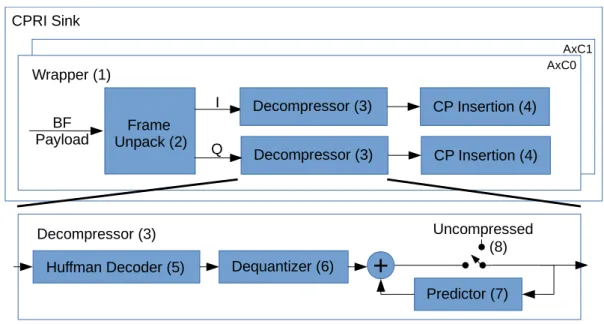
- Decompressor Implementation
- Huffman Decoder Block
- Prediction Filter Block
- Cyclic Prefix Insertion Block
This additional protocol layer is further described in section 3.2.1 and is part of the frame unpacking block. In the second step, the uncompressed samples are received and forwarded to the predictor. It receives the compressed stream and returns an estimate of the original LTE signal, as shown in Figure 3.8.
The initial concatenation is necessary because the bit width of the next code word is unknown until the comparison with the dictionary. 41, it is possible to use multiple right-shifted copies of the input and a multiplexer to update a register. This step of the block is asynchronous, so it does not add any clock cycle delay to the decoder.
On the other hand, the CP itself is a source of redundancy for the LTE signal. As a result, for an LTE signal with a bandwidth of 20 MHz, the number of samples in the CP is 160 for the first symbol of the LTE slot and 144 for the remaining symbols, as shown in Table 3.3. In PUSH FSM, states S0 and S1 are intended to generate the prefix of the first lock symbol.
States S0 and S1 are executed for the first OFDM symbol of the slot, while the other states are executed in the cycle for the other OFDM symbols.
Testbed evaluation
- Compression Evaluation
- The Phase Noise of recovered clock
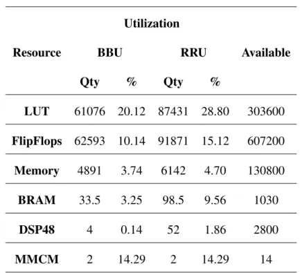
In this scenario, PLL dejittering was used to multiply the reference clock frequency. An external PLL board was then used to increase the slew rate of the signal generated by the FPGA. Together, these subsystems use approximately 30% of the FPGA resources for the BBU and RRU, as detailed in Table 4.1.
48 Another evaluation method used was the measurement of the phase noise of the clock signal obtained by PTP. Again, VSA was used to measure the phase noise characteristics of the clock in different scenarios. For example, how the addition of a second hop in the network affects the phase noise of the recovered clock.
50 frame structure of the Fronhtaul packets, it is possible to derive the overhead and link usages for each protocol header as shown in Table 4.3. The testbed has also been validated through the measurements of the Phase Noise of the PTP synchronized clock. In addition, the same clock signal is used in the phase noise measurements shown in this work.
Finally, it is essential to estimate the phase noise damages due to the increase in the number of hops in the network connection.
Conclusion
Future Works
Because the implemented testbed is essentially built from programmable sources (VHDL and C), it can be extended to evaluate virtually any solution required for fronthaul over Ethernet. Furthermore, future work can be divided into four main areas: infrastructure, compression, synchronization and transport. The infrastructure domain is related to the basic architecture of the test rig and the development of its functions.
The synchronization area includes the synchronization solution applied between the different endpoints of the network.
Publication
Callendar, "International Mobile Telecommunications-2000 Standards Efforts Of The ITU [Guest Editorial],"IEEE Personal Communications, vol. Niu, "Redesigning fronthaul for next-generation networks: beyond baseband samples and point-to-point links," IEEE Wireless Communications, vol. Le, "Massive MIMO and mmWave for 5G Wireless HetNet: Potential Benefits and Challenges," IEEE Vehicular Technology Magazine, vol.
Sobelman, "Architectures for multi-gigabit wire-linked clock and data recovery," IEEE Circuits and Systems magazine, vol. 17] Open Base Station Architecture Initiativeet al., “BTS System Reference Document, Version 2.0,”URL: http://www. 24] “IEEE Standard for an Accurate Clock Synchronization Protocol for Networked Measurement and Control Systems,” IEEE Std pp.
Sayana, “Coordinated multipoint transmission and reception in LTE-advanced: deployment scenarios and operational challenges,” IEEE Communications Magazine, vol. Society, “IEEE Standard for a Precision Clock Synchronization Protocol for Networked Measurement and Control Systems,” July 2008. 39] “AD-FMCOMMS2-EBZ - AD9361 Software Defined Radio Board,” available at: http://www. .analog.com/en/design-center/evaluation-hardware-and-software/.
Morgan, "Adaptive packet selection for clock recovery," i 2010 IEEE International Symposium on Precision Clock Synchronization for Measurement, Control and Communication, Sept 2010, pp.


![Figure 2.3: CPRI Basic Frame internal structure [1].](https://thumb-eu.123doks.com/thumbv2/123dok_br/19745540.0/31.892.305.627.132.359/figure-2-3-cpri-basic-frame-internal-structure.webp)
![Figure 2.5: CPRI naming convention and frame structure [1].](https://thumb-eu.123doks.com/thumbv2/123dok_br/19745540.0/32.892.160.750.210.516/figure-2-5-cpri-naming-convention-frame-structure.webp)
![Figure 2.6: Overview of OBSAI building blocks [2].](https://thumb-eu.123doks.com/thumbv2/123dok_br/19745540.0/33.892.159.769.523.892/figure-2-6-overview-of-obsai-building-blocks.webp)