A subset of the latest technical data is available on Daikin's regional website (publicly accessible). The fixing method of the indoor unit MUST be in accordance with the instructions from this manual. The connection diagram, which is delivered with the unit, is located on the inside of the switch box cover of the indoor unit.
All wiring MUST be carried out by an authorized electrician and MUST comply with applicable legislation. The backup heater MUST have a dedicated power supply and MUST be protected by the safety devices required by applicable legislation. Any damage or missing parts MUST be reported immediately to the claims agent of the carrier.
Indoor unit
- To remove the accessories from the indoor unit
- To handle the indoor unit
- Installation site requirements of the indoor unit
- Special requirements for R32 units
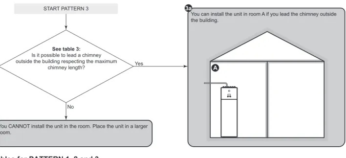
- Installation patterns
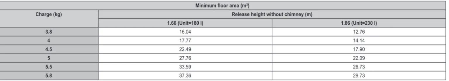
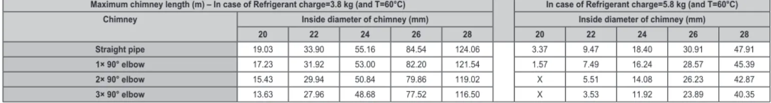
Minimum floor area requirements depend on the height of the refrigerant outlet in the event of a leak. If the chimney is led outside the building, there are no longer requirements regarding the minimum floor area. You can also use the floor area of the adjacent room (= room B) by providing ventilation openings between the two rooms.
If the opening starts from the floor, the height of the opening must be ≥20 mm. The bottom of the opening must be ≤100 mm from the floor of an unoccupied room. If the opening starts from the floor, the height of the opening must be ≥20 mm.
Opening and closing the unit
To open the indoor unit
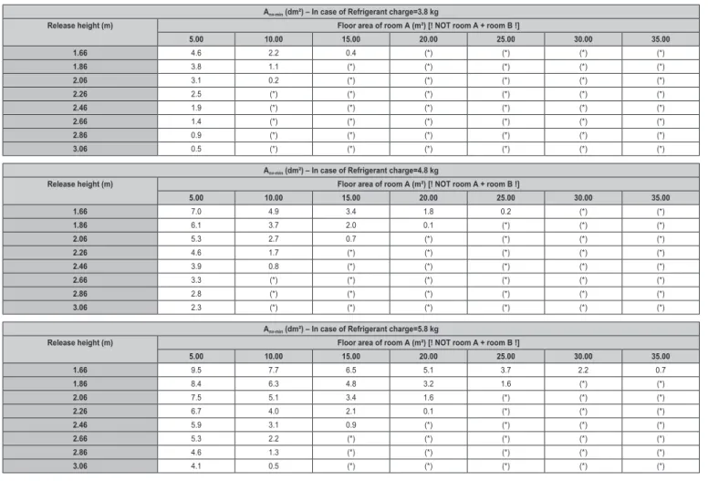
For this model there is no minimum floor area requirement if you provide 2 openings (one at the bottom, one at the top) between the room and the outside to provide natural ventilation. It should be ≥50% of Anv-min (minimum bottom opening area as specified in the table below). Anv-min (minimum area of the bottom opening for natural ventilation) The minimum area of the bottom opening for natural ventilation between the unoccupied room and the outside depends on the total refrigerant in the system.
To lower the switch box on the indoor unit
To close the indoor unit
Mounting the indoor unit
- To install the indoor unit
- To connect the drain hose to the drain
- Refrigerant piping requirements
- Refrigerant piping insulation
You must connect the drain pipe to a suitable drain in accordance with applicable legislation. If brazing is required, follow the guidelines in the installer's reference manual. Temperature class and pipe thickness:. a) Depending on applicable legislation and the maximum working pressure of the unit (see “PS High” on the unit nameplate), a larger pipe thickness may be required.
If the temperature is higher than 30°C and the humidity is higher than RH 80%, the thickness of the insulation materials should be at least 20 mm to prevent condensation on the insulation surface.
Connecting refrigerant piping
To connect the refrigerant piping to the indoor unit
Preparing water piping
To check the water volume and flow rate
Connecting water piping
- To connect the water piping
- To connect the recirculation piping
- To fill the water circuit
- To fill the domestic hot water tank
- To insulate the water piping
To prevent blockage of the pump rotor, start the unit as soon as possible after filling the water circuit. Make sure both vent valves (one on the magnetic filter and one on the backup heater) are open. 1 Open each hot water tap in turn to vent the system pipes.
5 Manually operate the field-installed relief valve to ensure a free flow of water through the discharge pipe. The piping in the entire water circuit MUST be insulated to prevent condensation during cooling operation and reduction of the heating and cooling capacity. Make sure the electrical wires DO NOT touch the refrigerant gas pipe, which can be very hot.
Guidelines when connecting the electrical wiring
Connections to the indoor unit
- To connect the main power supply
- To connect the backup heater power supply
- To connect the shut-off valve
- To connect the electricity meters
- To connect the domestic hot water pump
- To connect the alarm output
- To connect the space cooling/heating ON/OFF
- To connect the changeover to external heat source
- To connect the power consumption digital inputs
- To connect the safety thermostat (normally closed
- To connect a Smart Grid
You must connect the wired room thermostat (digital or analog) to the multi-zoning base unit. Separate connection to the indoor unit is required:. if the preferred kWh rate power supply is interrupted when active, OR. if the indoor unit's power consumption is not allowed by the preferred kWh rate power supply when it is active. To ensure that the unit is fully grounded, ALWAYS connect the power supply to the backup heater and ground cable.
2 Connect the valve control cable to the appropriate terminals as shown in the figure below. 2 Connect the electricity meter cable to the corresponding terminals as shown in the figure below. 2 Connect the domestic hot water pump cable to the corresponding terminals as shown in the figure below.
2 Connect the alarm output cable to the appropriate terminals as shown in the illustration below. 2 Connect the cooling/heating ON/OFF output cable to the appropriate terminals as shown in the illustration below. 2 Connect the jumper with the external heat source cable to the appropriate terminals as shown in the illustration below.
2 Connect the power consumption digital input cable to the appropriate terminals as shown in the illustration below. 2 Connect the safety thermostat cable (normally closed) to the appropriate terminals as shown in the illustration below.
After connecting the electrical wiring to the indoor unit
To access the most used commands
3 Turn the left knob to select the first part of the setting and confirm by pressing the knob. When you change the overview settings and you go back to the home screen, the user interface will show a pop-up screen and request to restart the system.
Configuration wizard
- Configuration wizard: Language
- Configuration wizard: Time and date
- Configuration wizard: System
- Configuration wizard: Backup heater
- Configuration wizard: Main zone
- Configuration wizard: Additional zone
- Configuration wizard: Tank
The automatic emergency setting can only be set in the menu structure of the user interface. If your system layout includes 2 AWT zones, you must install a mixing station before the main AWT zone. The main leaving water temperature zone consists of the higher loaded heat emitters and a mixing station to achieve the desired leaving water temperature.
Capacities for the various backup heater steps must be set for the energy metering function and/or energy consumption control to function properly. It can also be chosen to have a higher second step capacity in case of emergency. During normal operation, the capacity of the second step of the backup heater at the rated voltage is equal to.
The capacity difference between the second and first stage of the backup heater at rated voltage. In room thermostat control, the Emitter type affects the maximum modulation of the desired leaving water temperature and the possibility of using the automatic cooling/heating changeover based on the indoor ambient temperature. Waste water The unit's operation is determined based on the waste water temperature, regardless of the actual room temperature and/or heating or cooling needs in the room.
Room thermostat The operation of the unit is determined based on the ambient temperature of the special Human Comfort Interface (BRC1HHDA used as room thermostat). In weather-dependent mode, the desired leaving water temperature depends on the outdoor temperature. In Fixed LWT setpoint mode, the scheduled actions consist of the desired leaving water temperatures, preset or adjusted.
When programming the schedule, you can use the comfort setpoint as a preset value.
Weather-dependent curve
What is a weather-dependent curve?
When you later want to change the save setpoint, you only need to do it in one place. This function stops the tank heating even if the set point has NOT been reached. When the tank temperature rises above this value, hot water preparation and space heating/cooling are performed sequentially.
When the tank temperature drops below the reheat temperature minus the reheat hysteresis temperature, the tank heats up to the reheat temperature.
Slope-offset curve
Using weather-dependent curves
To change the type for all zones (main + additional) and for the tank, go to [2.E] Main zone > WD curve type. You cannot configure a curve with temperatures higher or lower than the set maximum and minimum setpoints for that zone or tank. Fine-tuning the weather-dependent curve: 2-point curve The following table describes how to fine-tune the weather-dependent curve of an area or tank:.
Settings menu
Main zone
Additional zone
Information
Menu structure: Overview installer settings
If the backup heater is available, the voltage, configuration and capacity must be set on the user interface. There are NO damaged components or pinched pipes inside the indoor and outdoor units.
Checklist during commissioning
- To check the minimum flow rate
- To perform an air purge
- To perform an operation test run
- To perform an actuator test run
- To perform an underfloor heating screed dryout
The general commissioning checklist is complementary to the instructions in this chapter and can be used as a guideline and reporting template during commissioning and handover to the user. 4 Read the flow rate(a) and modify the bypass valve. setting to reach the minimum required flow rate + 2 l/. a) During pump test run, the unit may operate below the minimum required flow rate. Before clearing air from heat emitters or collectors, check whether or is displayed on the home screen of the user interface.
If the outdoor temperature is outside the operating range, the unit may NOT operate or provide the required performance. During the test operation, the correct operation of the unit can be verified by monitoring its leaving water temperature (heating/cooling mode) and tank temperature (domestic hot water mode). Make sure the user has printed documentation and ask them to keep it for later reference.
Inform the user that he can find the complete documentation at the URL mentioned earlier in this manual. Explain to the user how to operate the system correctly and what to do in case of problems. The full set of latest technical data is available on the Daikin Business Portal (authorization required).
Wiring diagram: Indoor unit
Indoor unit powered by outdoor Indoor unit powered by outdoor Power supply with normal kWh rate Power supply with normal kWh rate Only for normal power supply. For HV smart grid For high voltage Smart Grid For LV smart grid For low voltage Smart Grid For safety thermostat For safety thermostat. Only for demand PCB option Only for demand PCB option Only for digital I/O PCB option Only for digital I/O PCB option Options: ext.
Options: external heat source output, alarm output Options: On/OFF output Options: ON/OFF output Current limitation digital inputs: 12. 12 V DC / 12 mA detection (voltage supplied by printed circuit board) Room C/H On/OFF output Room cooling /heating ON/OFF. Only for heat pump convector Only for heat pump convector Only for wired ON/OFF.
Power limitation demand input 3 Power limitation demand input 2 Power limitation demand input 1 FIELD SUPPLY OPTIONAL COMPONENT.