For experimental testing, the scaled model must replicate the desired aeroelastic response at the scale of the full-size wing and therefore aeroelastic scaling methodologies must be developed. The effects of the chosen primary quantities and of the modal matching approach are analyzed using two modal matching approaches (direct modal matching and the Coordinate Modal Assurance Criterion, COMAC) and two scaling methodologies (mass and stiffness distribution matched simultaneously and successively), and The option of using a laminated composite beam for the reduced model is analyzed.
Motivation
Topic Overview and State of the Art
With this methodology, it was possible to reproduce the adjusted natural frequencies and the adjusted flutter speed of the vehicle at full scale, but not the reduced frequencies. The newly developed method (Method 3) uses two different optimization routines to match the nonlinear static response and mode shapes of the entire model.
Composite Materials in Aeroelasticity
Kameyama and Fukunaga [19] investigated the effect of laminate configuration on the flutter and divergence characteristics of composite plate wings. To investigate the effect of the laminate configuration, the flakiness and divergence properties were represented on the lamination parameter plane.
Thesis Outline
20] investigated the use of drag-controlled composites to tailor the aeroelastic behavior of composite wings. They found that it is possible to influence the aeroelastic behavior in both beneficial and detrimental ways using drag control.
Aeroelasticity
- Divergence
- Flutter
- Buffeting
- Control Reversal
- Limit Cycle Oscillation
Flutter is a dynamic instability that occurs in an aircraft in flight caused by positive feedback between the body's deflection and the force exerted by the fluid flow, at a speed called the flutter speed, where the elasticity of the structure plays an essential role in the instability. Control reversal is a condition occurring in flight, at a speed called the control reversal speed, at which the intended effects of the displacement of a given component of the control system are completely nullified by elastic deformations of the structure. Wing torques due to deflected ailerons increase as the square of the speed, while elastic restoring torques remain the same.
Aeroelastic Scaling
Equations of Motion
When considering an aileron, where the function is to change the lifting capacity of the wings, with downward rudders the lift on the wing is increased and with upward rudders it is reduced. However, the warping deflection will also produce a twisting moment for downward camber deflections or torque for upward deflections. One or more non-linearities, such as geometric, aerodynamic, stiffness or structural damping, in the system act to limit the amplitude of the movement [22].
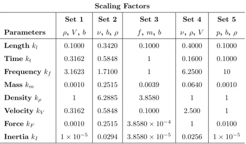
Scaling Factors
If the amplitude is large enough, the motion can damage the aircraft or supplies attached to the wings [23]. These primary quantities will be freely chosen and will determine the rest of the scale factors. These consist of the ratio between the parameter value of the scaled model and the parameter value of the full-size wing.
Parameters to Match
The parameters to be linked are those that are free after constraints are applied to the model, up to the number of primary dimensions involved in the governing equations. The scale factors required for the analysis of an aeroelastic scale model are: length (kl), time (kt), frequency (kf), mass (kM), air density (kρ), speed (kV), force (kF) , and inertia (kI). Frequencies and mode shapes are mandatory, as it is necessary to achieve the same dynamic response.
Composite Materials
- Local Referential
- Global Referential
- Symmetric Lay-up
- Hybrid Composites
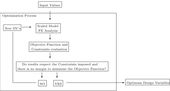
The x1 axis is parallel to the fiber, the x2 axis is transverse to the fiber direction in the plane of the lamina, and the x3 axis is perpendicular to the plane of the lamina, as shown in Figure 2.2. Recently, the incorporation of several different types of fibers into a single matrix has led to the development of hybrid composites. Before the optimization process, a finite element (FE) analysis should be performed for the full-size wing to obtain the shapes, frequencies and displacements.
![Figure 2.2: Local referential [26].](https://thumb-eu.123doks.com/thumbv2/123dok_br/19768578.0/34.892.297.592.273.454/figure-2-2-local-referential-26.webp)
Simultaneous Mass and Stiffness Distribution Matching
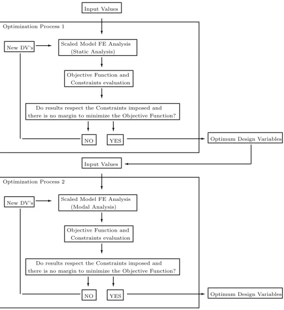
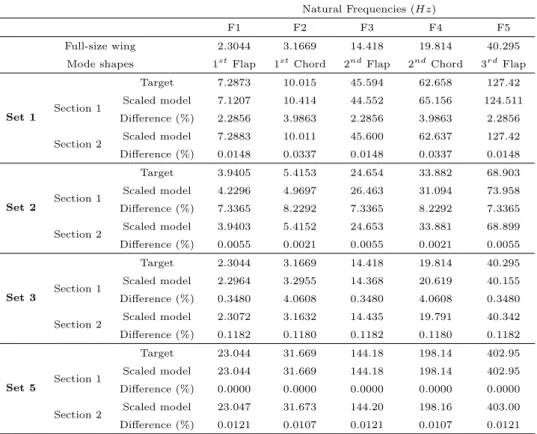
With the initial design variables, the algorithm performs an FE analysis to obtain the mode shapes and frequencies of the scaled model, comparing the results to the target values (the scaled values of the FE analysis results of the full-size wing). To match the stiffness and mass distribution, the frequencies and mode shapes of the scale model must match those of the full-size wing. Due to the fact that the global search algorithm does not use the same number of initial points in each optimization process, it is possible to obtain the same minimum value of the objective function and the optimal DV solution, but with different computational time.
Sequential Mass and Stiffness Distribution Matching
Optimization Process 1
To do this, we first obtain the full-size deformation of the wing by applying a predetermined vertical force to the tip of the wing. The initial design variables for optimization process 1 are the section dimensions of the reduced model. As described in methodology 1, the Global Search algorithm is used to accelerate the selection of the initial point.
Optimization Process 2
To ensure that the mass distribution is scaled appropriately, the frequencies and mode shapes of the scaled-down model must match the scaled frequencies and mode shapes of the full-size wing. The absolute value of the difference between the target frequency and the model frequency is used for frequency matching. The design variables for optimization process 2 are the radius and positions of the structural masses added to the reduced model.
Computational Tools
Structural Model
To match the mode shapes, we resort to COMAC, as this method has been shown to give better results (see Section 4.5.1). For the non-linear constraints, the same option described in method 1 is considered, which corresponds to equation 3.9. To do so, the stiffness matrix becomes dependent on the deformed state and an iterative method is required.
Aerodynamic Model
Aeroelastic Model
Depending on the type of experimental test for which the model is intended (wind tunnel test or flight test), and on the characteristics of the test, some limitations will be added to the scale model: space (due to the dimensions limited parameters of the wind tunnel ), wind speed, air density (can be changed in the wind tunnel test, but it can be expensive; . for the flight test the altitude can be determined based on this parameter, but it can challenging life to achieve the correct value), thicknesses and internal structure (structures that are too thin become more difficult to build and less resistant), among others. With the objective of analyzing the influence of the choice of primary quantities in the scaling procedure, five different groups will be defined and implemented in a simple model.
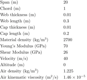
Full-Size Wing
Scaled Model
The internal structure is that which, with some level of accuracy, will give the same aeroelastic behavior of the full-size wing. For section 1, the DVs are the thicknesses of the caps and webs (tc andtw, respectively) and the lengths (rod c, respectively), and for section 2, the DVs are the height and width (candw, respectively). The material in the scaled model is also aluminum with the same properties as the full-size wing model, described in Table 4.1.
Scaling Factors
With it, it is possible to choose the desired spacing, speed and air density of the scaled model. The initial values selected for the main quantities of the scaled model for groups 1, 3 and 5 are listed in Table 4.3. Therefore for group 4 the flight condition of the full size wing does not need to be changed and the speed value is determined in addition to the air properties for the reduced model.

Methodology
Results
- Modal Matching Approach Analysis
- Reynolds Matching Analysis
- Primary Quantities Final Analysis
- Methodologies Analysis
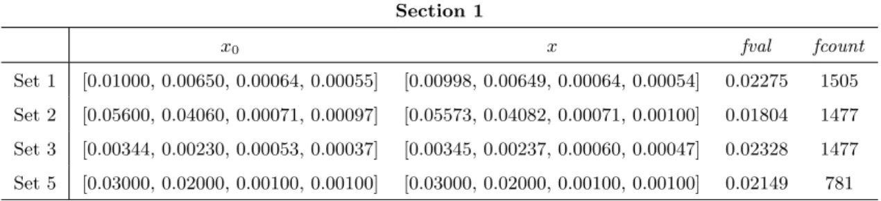
However, a smaller minimum value of the objective function does not necessarily mean a better modal fit. The final dimensions, material properties and condition of flight of the reduced model for each set of primary quantities are presented in Table 4.10. Also the best overall result of the objective function value and the number of function calls are listed.
Full-Size Wing
To verify whether it is possible to obtain a scaled-down model of laminated composite material that can replicate the scaled aeroelastic response of the full-size model, a scaling procedure was developed.
Scaled Model
Methodology
For the material properties of the fibers, the limits are based on the options provided. The limits for the thicknesses of each layer and the cross-section length are defined by trial and error.
Results
The number of finite element function calls needed to perform the optimization process using direct modal matching is lower than the COMAC approach (the COMAC approach needs 45.35.% more function calls), despite being higher compared to a metallic reduced model due to the fact that more DVs are involved.

Full-Size Wing
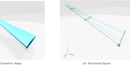
The geometry of the new wing is illustrated in Figure 6.1 and its main characteristics are given in Table 6.2. As for the side layers, they consist of the spars of the wing, which are located at 25% and 75% of the local chord of the airfoil. The skin thickness ts in the upper and lower layers is dimensionless by the maximum thickness of the support surface.
Scaled Model
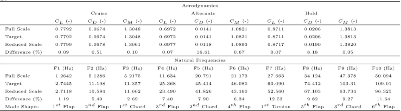
The dynamic analysis and scaling procedure is performed considering three flight conditions: cruise, alternating and hold. The angle of attack at which the analyzes were calculated was defined so that the wing lift corresponds to the weight of the aircraft (58 tons). All analyzes performed for this wing model were performed using an in-house nonlinear aeroelastic framework [35].
Results
Considering set 1, Mach number similarity was not achieved, resulting in a poor match between the aerodynamic and structural response for alternate flight conditions and stall flight conditions. Therefore, the air properties (density and temperature) were modified to ensure similarity of Mach numbers for these cases. Finally, when dealing with a more complex wing, the set of 5 primary quantities provided good results, despite the Froude number not being similar.
Future Work
In 48ste AIAA/ASME/ASCE/AHS/ASC Structures, Structural Dynamics, and Materials Conference, volume 1887, Honolulu, Hawaii, April 2007. In 48ste AIAA/ASME/ASCE/AHS/ASC Structures, Structural Dynamics, and Materials Conference, bladsy, 1889, Honolulu, Hawaii, April 2007. In 53ste AIAA/ASME/ASCE/AHS/ASC-strukture, strukturele dinamika en materiaalkonferensie, AIAA, volume 1454, Honolulu, Hawaii, April 2012.
![Figure 2.1: Collar triangle of forces [6].](https://thumb-eu.123doks.com/thumbv2/123dok_br/19768578.0/29.892.258.638.706.1044/figure-2-1-collar-triangle-of-forces-6.webp)