OPERATION MANUAL
EWYQ080DAYN EWYQ100DAYN EWYQ130DAYN EWYQ150DAYN EWYQ180DAYN EWYQ210DAYN EWYQ230DAYN EWYQ250DAYN
Packaged air-cooled water chillers
C
ONTENTS PageIntroduction ... 1
Technical specifications ... 1
Electrical specifications ... 2
Important information regarding the refrigerant used ... 3
Description ... 3
Function of the main components... 4
Safety devices... 5
Internal wiring - Parts table ... 6
Before operation... 7
Checks before initial start-up ... 7
Water supply ... 7
Power supply connection and crankcase heating... 8
General recommendations ... 8
Operation ... 8
Digital controller ... 8
Working with the unit ... 9
Advanced features of the digital controller... 12
Troubleshooting ... 20
Maintenance... 23
Maintenance activities ... 23
Disposal requirements ... 24
I
NTRODUCTIONThis operation manual concerns packaged air-cooled water chillers of the Daikin EWYQ-DAYN series. These units are provided for outdoor installation and used for cooling and heating applications.
The EWYQ units can be combined with Daikin fan coil units or air handling units for air conditioning purposes. They can also be used for supplying water for process cooling.
This manual has been prepared to ensure adequate operation and maintenance of the unit. It will tell you how to use the unit properly and will provide help if problems occur. The unit is equipped with safety devices, but they will not necessarily prevent all problems caused by improper operation or inadequate maintenance.
In case of persisting problems contact your local Daikin dealer.
Technical specifications (1)
EWYQ080DAYN EWYQ180DAYN EWYQ100DAYN EWYQ210DAYN EWYQ130DAYN EWYQ230DAYN EWYQ150DAYN EWYQ250DAYN
Packaged air-cooled water chillers
Operation manual
READ THIS MANUAL ATTENTIVELY BEFORE STARTING UP THE UNIT. DO NOT THROW IT AWAY. KEEP IT IN YOUR FILES FOR FUTURE REFERENCE.
Before starting up the unit for the first time, make sure that it has been properly installed. It is therefore necessary to carefully read the installation manual supplied with the unit and the recommendations listed in "Checks before initial start-up" on page 7.
(1) Refer to the engineering data book for the complete list of specifications.
General EWYQ 080 100 130
Dimensions HxWxD (mm) 2311x2000x2631
Weight
• machine weight (kg) 1400 1450 1550
• operation weight (kg) 1415 1465 1567
Connections
• chilled water inlet and outlet 3" OD 3" OD 3" OD
• evaporator drain 1/2" G 1/2" G 1/2" G
Internal water volume (l) 15 15 17
Expansion vessel (only for OPSP, OPTP and OPHP)
• volume (l) 35 35 35
• pre-pressure (bar) 1.5 1.5 1.5
Safety valve water circuit
(bar)
3.0 3.0 3.0
Pump (only for OPSP)
• type Vertical in-line pump
• model (standard) TP 50-240/2 TP 50-240/2 TP 65-230/2
Compressor
Type semi-hermetic scroll compressor
Qty x model 2x SJ180-4 2x SJ240-4 4x SJ161-4
Speed (rpm) 2900 2900 2900
Oil type FVC68D FVC68D FVC68D
Oil charge volume (l) 2x 6.2 2x 6.2 4x 3.3
Condenser
Nominal air flow (m3/min) 780 780 800
No. of motors x output (W) 4x 500 4x 500 4x 600
Evaporator
Model P120TH P120TH DV47HP
General EWYQ 150 180 210
Dimensions HxWxD (mm) 2311x2000x2631 2311x2000x3081 Weight
• machine weight (kg) 1600 1850 1900
• operation weight (kg) 1619 1875 1927
Connections
• chilled water inlet and outlet 3" OD 3" OD 3" OD
• evaporator drain 1/2" G 1/2" G 1/2" G
Internal water volume (l) 19 25 27
Expansion vessel (only for OPSP, OPTP and OPHP)
• volume (l) 35 35 35
• pre-pressure (bar) 1.5 1.5 1.5
Safety valve water circuit
(bar)
3.0 3.0 3.0
Pump (only for OPSP)
• type Vertical in-line pump
• model (standard) TP 65-230/2 TP 65-260/2 TP 65-260/2
Compressor
Type semi-hermetic scroll compressor
Qty x model 4x SJ180-4 2x SJ180-4 +
2x SJ240-4 4x SJ240-4
Speed (rpm) 2900 2900 2900
Oil type FVC68D FVC68D FVC68D
Oil charge volume (l) 2x 6.2 2x 6.2 + 2x 6.2 4x 6.2 Condenser
Nominal air flow (m3/min) 860 1290 1290
No. of motors x output (W) 4x 1000 6x 1000 6x 1000 Evaporator
Model DV47HP DV58HP DV58HP
Electrical specifications (1)
General EWYQ 230 250
Dimensions HxWxD (mm) 2311x2000x4833
Weight
• machine weight (kg) 3200 3300
• operation weight (kg) 3239 3342
Connections
• chilled water inlet and outlet 3" 3"
• evaporator drain 1/2" G 1/2" G
Internal water volume (l) 39 42
Expansion vessel (only for OPSP, OPTP and OPHP)
• volume (l) 50 50
• pre-pressure (bar) 1.5 1.5
Safety valve water circuit
(bar)
3.0 3.0
Pump (only for OPSP)
• type Vertical in-line pump
• model (standard) TP 65-260/2 TP 65-260/2
Compressor
Type semi-hermetic scroll compressor
Qty x model 2x SJ240-4 +
2x SJ300-4 4x SJ300-4
Speed (rpm) 2900 2900
Oil type FVC68D FVC68D
Oil charge volume (l) 2x 6.2 + 2x 6.2 4x 6.2
Condenser
Nominal air flow (m3/min) 1600 1600
No. of motors x output (W) 8x 600 8x 600
Evaporator
Model DV58HP DV58HP
EWYQ 080 100 130 150
Power supply YN
• Phase 3~
• Frequency (Hz) 50
• Voltage (V) 400
• Voltage tolerance (%) ±10
Unit
• Nominal running current (A) 60 72 88 113
• Maximum running current (A) 96 120 160 177
• Recommended fuses according to IEC 269-2
(A) 3x 125 gL 3x 160 gL 3x 200 gL 3x 200 gL Compressor
• Circuit 1 Circuit 2
(hp) (hp) 15 + 15
—
20 + 20
—
13 + 13 13 + 13
15 + 15 15 + 15
• Phase 3~
• Frequency (Hz) 50
• Voltage (V) 400
• Maximum running current Circuit 1
Circuit 2
(A) (A) 39 + 39
—
51 + 51
—
35 + 35 35 + 35
39 + 39 39 + 39 Control and fan motor
• Phase 1~
• Frequency (Hz) 50
• Voltage (V) 230 V
• Maximum running current (A) 4x 1.5 4x 1.5 4x 1.6 4x 2.3 Pump
• Power (kW) 2.2 2.2 3 3
• Maximum running current (A) 4.5 4.5 6.3 6.3
Heater tape (OP10)
• Supply voltage (V) 230 V ±10%
• Power (standard) (OPSP) (OPBT)
1x 300 W 2x 300 W 2x 300 W + 150 W
• Optional field heater maximum 1 kW
• Recommended fuses (A) 2x 10
EWYQ 180 210 230 250
Power supply YN
• Phase 3~
• Frequency (Hz) 50
• Voltage (V) 400
• Voltage tolerance (%) ±10
Unit
• Nominal running current (A) 131 144 162 181
• Maximum running current (A) 209 233 262 290
• Recommended fuses according to IEC 269-2
(A) 3x 250 gL 3x 250 gL 3x 300 gL 3x 355 gL Compressor
• Circuit 1 Circuit 2
(hp) (hp) 20 + 15
20 + 15
20 + 20 20 + 20
25 + 20 25 + 20
25 + 25 25 + 25
• Phase 3~
• Frequency (Hz) 50
• Voltage (V) 400
• Maximum running current Circuit 1
Circuit 2
(A)
(A) 51 + 39 51 + 39
51 + 51 51 + 51
65 + 51 65 + 51
65 + 65 65 + 65 Control and fan motor
• Phase 1~
• Frequency (Hz) 50
• Voltage (V) 230 V
• Maximum running current (A) 6x 2.3 6x 2.3 8x 1.6 8x 1.6 Pump
• Power (kW) 4 4 4 4
• Maximum running current (A) 8.0 8.0 8.0 8.0
Heater tape (OP10)
• Supply voltage (V) 230 V ±10%
• Power (standard) (OPSP) (OPBT)
1x 300 W 2x 300 W 2x 300 W + 150 W
• Optional field heater maximum 1 kW
• Recommended fuses (A) 2x 10
Important information regarding the refrigerant used
This product contains fluorinated greenhouse gases covered by the Kyoto Protocol.
Refrigerant type: R410A GWP(1) value: 1975
(1) GWP = global warming potential
Periodical inspections for refrigerant leaks may be required depending on European or local legislation. Please contact your local dealer for more information.
D
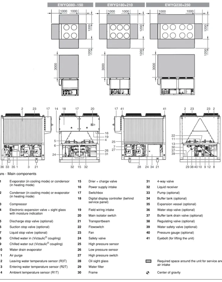
ESCRIPTIONThe EWYQ air-cooled water chillers are available in 8 standard sizes.
Figure - Main components 35
12001200
1000
16 19 4 1000
3 33
36
26 31 5
24 23
28 34 21 4010 9
1
3000
41 41
20
2 14 18 17 2 23 23 2
15
21 32 32 24
6
277 25
8
29 12
39 11
37 30 13 22
38
17 17
12001200
1000 1000
3000
EWYQ080~150 EWYQ180+210
12001200
1000 1000
3000
EWYQ230+250
1 Evaporator (in cooling mode) or condensor (in heating mode)
15 Drier + charge valve 31 4-way valve
16 Power supply intake 32 Liquid receiver
2 Condenser (in cooling mode) or evaporator (in heating mode)
17 Switchbox 33 Pump (optional)
18 Digital display controller (behind service panel)
34 Buffer tank (optional)
3 Compressor 35 Expansion vessel (optional)
4 Electronic expansion valve + sight glass with moisture indication
19 Field wiring intake 36 Water stop valve (optional)
20 Main isolator switch 37 Buffer tank drain valve (optional)
5 Discharge stop valve (optional) 21 Transportbeam 38 Regulating valve (optional)
6 Suction stop valve (optional) 22 Flowswitch 39 Water safety valve (optional)
7 Liquid stop valve (optional) 23 Fan 40 Pressure gauge (optional)
8 Chilled water in (Victaulic® coupling) 24 Safety valve 41 Eyebolt (for lifting the unit) 9 Chilled water out (Victaulic® coupling) 25 High pressure sensor
10 Water drain evaporator 26 Low pressure sensor
11 Air purge 27 High pressure switch
12 Leaving water temperature sensor (R3T) 28 Oil sight glass Required space around the unit for service and air intake
13 Entering water temperature sensor (R2T) 29 Water filter
14 Ambient temperature sensor (R1T) 30 Frame Center of gravity
Function of the main components
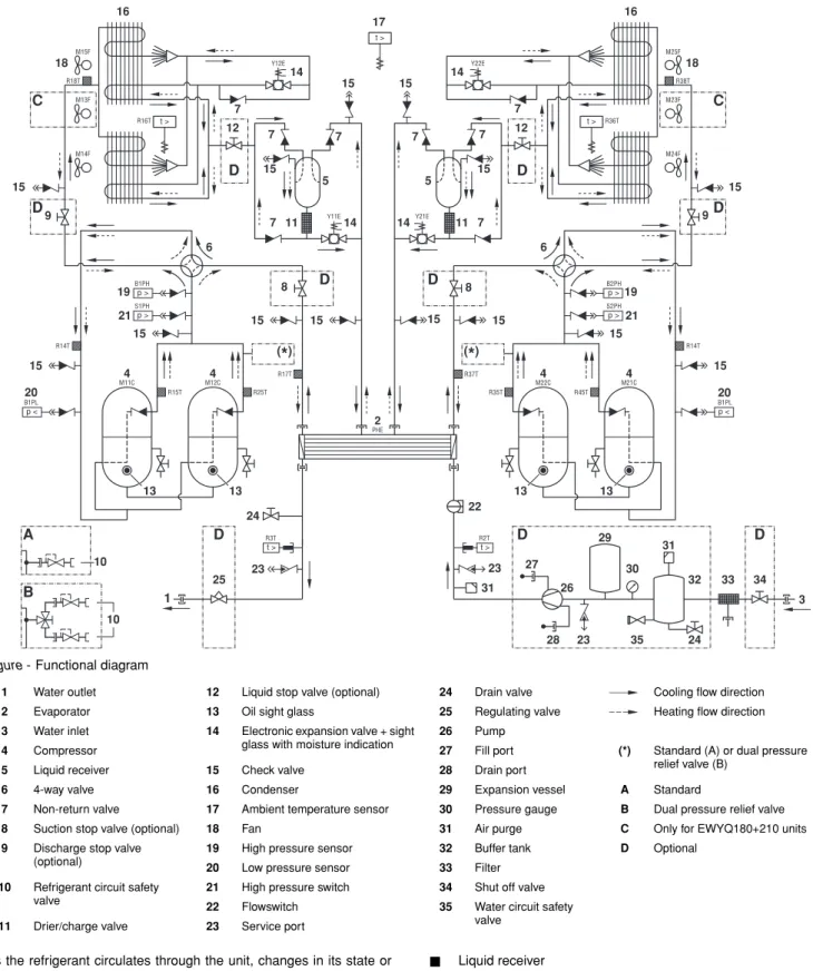
Figure - Functional diagram
As the refrigerant circulates through the unit, changes in its state or condition occur. These changes are caused by the following main components:
■ Compressor
The compressor (M*C) acts as a pump and circulates the refri- gerant in the refrigeration circuit. It compresses the refrigerant vapour coming from the evaporator at the pressure at which it can easily be liquefied in the condenser.
■ Condenser (in cooling mode) or evaporator (in heating mode) The function of the condenser is to change the state of the refrigerant from gaseous to liquid. The heat gained by the gas in the evaporator is discharged through the condenser to the ambient air, and the vapour condenses to liquid.
■ Liquid receiver
The liquid receiver prevents the plate heat exchanger from flooding with liquid in heating mode caused by a great difference between the volumes of coil and plate heat exchanger.
■ Filter/drier
The filter installed behind the condenser removes small particles from the refrigerant to prevent damage to the compressor and expansion valve.
The drier takes the water out of the system.
■ Expansion valve
The liquid refrigerant coming from the condenser enters the evaporator via an expansion valve. The expansion valve brings the liquid refrigerant to a pressure at which it can easily be evaporated in the evaporator.
p <
M12C M11C
M15F
M13F
M14F
R14T
B1PL
R15T R25T
R17T Y12E
PHE t >
2 4
4
13 13
17
11
20 18
16
C
15
14
t >
R16T
7 7
7
7
15
15 15
p >
B1PH
19
p >
S1PH
21
Y11E14 5
R18T
(
*
)15
15
p <
M22C M21C
M25F
M23F
M24F
R14T
B1PL R45T
R35T R37T
Y22E
4 4
13 13
11
20 18 16
C
15 15 14
t > R36T
7 7
7
7
15
15 15
p >
B2PH
19
p >
S2PH
21 14Y21E
5
R38T
(
*
)15
15 15
6 6
9 9
8
12 12
1 3
A D D D
10
B
10
22
25 24
23 27 30
29 31
31
28
26 32
24 35
34 33
t > t >
R3T R2T
D
D D
D
D
D
8
23
23
1 Water outlet 12 Liquid stop valve (optional) 24 Drain valve Cooling flow direction
2 Evaporator 13 Oil sight glass 25 Regulating valve Heating flow direction
3 Water inlet 14 Electronic expansion valve + sight glass with moisture indication
26 Pump
4 Compressor 27 Fill port (*) Standard (A) or dual pressure
relief valve (B)
5 Liquid receiver 15 Check valve 28 Drain port
6 4-way valve 16 Condenser 29 Expansion vessel A Standard
7 Non-return valve 17 Ambient temperature sensor 30 Pressure gauge B Dual pressure relief valve
8 Suction stop valve (optional) 18 Fan 31 Air purge C Only for EWYQ180+210 units
9 Discharge stop valve (optional)
19 High pressure sensor 32 Buffer tank D Optional
20 Low pressure sensor 33 Filter
10 Refrigerant circuit safety valve
21 High pressure switch 34 Shut off valve
22 Flowswitch 35 Water circuit safety
valve
11 Drier/charge valve 23 Service port
■ 4-way valve
The 4-way valve reverses the refrigerant flow in the unit to change from cooling mode to heating mode.
■ Evaporator
The main function of the evaporator is to take heat from the water that flows through it. This is done by turning the liquid refrigerant, coming from the condenser, into gaseous refrigerant.
■ Non-return valve
The non-return valve prevents the refrigerant from flowing in the wrong direction.
■ Water in/outlet connection
The water inlet and outlet connection allow an easy connection of the unit to the water circuit of the air handling unit or industrial equipment.
Safety devices
The unit is equipped with three kinds of safety device:
1 General safety devices
General safety devices shut down all circuits and stop the whole unit. For this reason the unit has to be manually put on again after a general safety occurred.
2 Circuit safety devices
Circuit safety devices shut down the circuit they protect, while the other circuits remain activated.
3 Part safety devices
Part safety devices shut down the part they protect.
An overview of all safety devices is given below.
■ Overcurrent relays
■ Overcurrent relay for compressors (only for SJ161-4) (circuit safety device)
The overcurrent relay protects the compressor motor in case of overload, phase failure or too low voltage.
■ Overcurrent relay for fans (part safety device)
The overcurrent relay protects the fan motors in case of overload, phase failure or too low voltage.
■ Overcurrent relay for pump (general safety device)
The overcurrent relay protects the pump in case of overload, phase failure or too low voltage.
When activated, the overcurrent relays have to be reset in the switch box and the controller needs to be reset manually.
■ Compressor SJ161-4 thermal protector (part safety devices) Compressor SJ161-4 is equipped with an internal overload motor protection to protect the unit against excessive current and temperature caused by overloading, low refrigerant flow or phase loss. The compressor will shut down and will automatically restart when temperature returns to normal. This is not detected by the controller.
■ Compressor SJ180-4 electronic protection module (circuit safety device)
Compressor SJ180-4 is equipped with an electronic protection module to provide for efficient and reliable protection against overheating, overloading, and phase loss. The controller will detect the shut down of the compressor. The controller needs to be reset manually. The compressor is internally protected against reverse phase.
■ Compressors SJ240-4 and SJ300-4 electronic protection modules (circuit safety device)
Compressors SJ240-4 and SJ300-4 are equipped with an electronic protection module to provide for efficient and reliable protection against overheating, overloading, phase loss and phase reversal. The controller will detect the shut down of the compressor. The controller needs to be reset manually.
■ Reverse phase protector (general safety device)
The reverse phase protectors prevent the unit from being operated in reverse phase. If the unit does not start, two phases of the power supply must be inverted.
■ Flowswitch (general safety devices) The unit is protected by a flowswitch (S1L).
When the water flow becomes lower than the minimum allowed water flow, the flowswitch shuts down the unit. When the water flow becomes normal, the protection resets automatically but the controller still needs to be reset manually.
■ Discharge thermal protectors (circuit safety devices)
The unit is equipped with discharge thermal protectors (R*T).
The protectors are activated when the temperature of the refrigerant leaving the compressor becomes too high. When the temperature returns to normal the controller needs to be reset manually.
■ Freeze-up protection (general safety devices)
The freeze-up protection prevents the water in the evaporator from freezing during operation.
■ When the outlet water temperature is too low, the controller shuts down the compressors. When the outlet water temperature returns to normal, the controller resets automatically.
■ When the refrigerant temperature is too low, the controller shuts down the unit. When the refrigerant temperature returns to normal, the controller needs to be reset manually.
■ Low pressure safety (circuit safety devices)
When the suction pressure of a circuit is too low, the circuit controller shuts down the circuit. When the pressure returns to normal, the safety device can be reset on the controller.
■ Pressure relief safety valve (general safety devices)
The safety valve is activated when the pressure in the refrigerant circuit becomes too high. If this occurs, shut down the unit and contact your local dealer.
■ High pressure setback (circuit safety device)
The high pressure setback prevents the high pressure to become too high so that high pressure switch is activated.
When the high pressure is too high, the controller shuts down the compressor. When the pressure returns to normal, the controller resets automatically.
■ High pressure switch (circuit safety devices)
Each circuit is protected by a high pressure switch (S*PH) which measures the condenser pressure (pressure at the outlet of the compressor).
When the pressure becomes too high, the pressure switch is activated and the circuit stops.
When the pressure becomes normal again, the protection resets automatically but the controller still needs to be reset manually.
The switch is factory-set and may not be adjusted.
■ Compressor protection function
The compressor protection function protects the compressor, while running in heating mode, from operating outside operation range.
If low pressure and high pressure temperatures are outside operation range, the controller shuts down the compressor.
When the low pressure and high pressure temperatures return to normal, the controller resets automatically.
The overcurrent relays are factory set and may not be adjusted.
Internal wiring - Parts table
Refer to the internal wiring diagram supplied with the unit. The abbreviations used are listed below:
A01P... PCB extension
A02P...**... PCB communication (only for option EKACPG) A4P... PCB wired remote controller
A5P...**... PCB wired remote controller (only for option EKRUPG)
A11P,A21P... PCB main controller circuit 1, circuit 2 A13P,A23P....**... Frequency inverter circuit 1, circuit 2
(only for option OPIF) A71P,A72P... PCB EEV driver
A73P... PCB EEV driver (only for EWYQ230+250) B1PH,B2PH... High pressure sensor circuit 1, circuit 2 B1PL,B2PL ... Low pressure sensor circuit 1, circuit 2 DS1... PCB DIP-switch
E1HS ...**... Switch box heater with fan
(only for EWYQ130~250 with option OPIF) E3H...**... Heater tape (only for option OP10) E4H...**... Heater tape
(only for option OP10, OPSP, OPHP or OPTP) E5H...* ... Field heater
E6H...**... Buffer tank heater
(only for option OP10 or OPBT) E7H...**... Switch box heater
(only for EWYQ080+100 with option OPIF) E11HC,E12HC ... Crankcase heater compressor circuit 1 E21HC,E22HC ... Crankcase heater compressor circuit 2
(only for EWYQ130~250) F1~F3 ...# ... Main fuses
F1U... Fuse for PCB F4,F5 ...# ... Fuse for heater
F6B ... Autofuse for primary of TR1 F8B ...**... Autofuse for switchbox heater
(only for option OPIF) F9B ... Autofuse for secondary of TR1
F11B,F12B ... Autofuse for compressors (M11C, M12C) (only for EWYQ130~250)
F14B,F24B ... Autofuse for fanmotors circuit 1, circuit 2 F15B,F25B ...**... Autofuse for fanmotors circuit 1, circuit 2
(only for option OPIF)
F16B ...**... Autofuse for pump (K1P) (only for option OPSP, OPHP, OPSC, OPTC and OPTP)
F17B ...**... Autofuse for pump (K2P) (only for options OPTC and OPTP) F21B,F22B ... Autofuse for compressors (M21C, M22C) H1P~H6P ...* ... Indication lamp for changeable digital outputs H11P,H12P ...* ... Indication lamp for operation compressor
circuit 1 M11C, M12C
H21P,H22P ...* ... Indication lamp for operation compressor circuit 2 M21C, M22C
HAP~HEP... LED PCB
K1A,K2A ... Auxiliary relay for compressor safety circuit 1, circuit 2
K1P...## .... Pump contactor (only for option OPSP, OPHP, OPSC, OPTC and OPTP)
K1R~K22R ... PCB relay
K1S...* ... Overcurrent relay pump K2P...**... Pump contactor
(only for options OPTC and OPTP) K3A... Auxiliary relay for heater tape K11M,K12M... Compressor contactor for circuit 1 K13F,K14F ... Fancontactor for circuit 1 K13S,K14S ... Fan overcurrent relay for circuit 1 K15F ... Fancontactor for circuit 1
(only for EWYQ080+100 and EWYQ180~250)
K15S ... Fan overcurrent relay for circuit 1
(only for EWYQ080+100 and EWYQ180~250) K16F ... Fancontactor for circuit 1
(only for EWYQ080+100 and EWYQ230+250) K16S ... Fan overcurrent relay for circuit 1
(only for EWYQ080+100 and EWYQ230+250) K21M,K22M ... Compressor contactor for circuit 2
(only for EWYQ130~250) K23F,K24F ... Fancontactor for circuit 2 (only for EWYQ130~250) K23S,K24S ... Fan overcurrent relay for circuit 2
(only for EWYQ130~250) K25F ... Fancontactor for circuit 2 (only for EWYQ180~250) K25S ... Fan overcurrent relay for circuit 2
(only for EWYQ180~250) K26F ... Fancontactor for circuit 2 (only for EWYQ230+250) K26S ... Fan overcurrent relay for circuit 2
(only for EWYQ230+250) M1F... Cooling fan for switch box
M1P... ** ... Pump motor 1(only for option OPSP, OPHP, OPSC, OPTC and OPTP)
M2P... ** ... Pump motor 2
(only for option OPTC and OPTP) M11C,M12C ... Compressor motors circuit 1 M13F,M14F ... Fan motors circuit 1 M15F... Fan motors circuit 1
(only for EWYQ080+100 and EWYQ180~250) M16F... Fan motors circuit 1
(only for EWYQ080+100 and EWYQ230+250) M21C,M22C ... Compressor motors circuit 2
(only for EWYQ130~250)
M23F,M24F ... Fan motors circuit 2 (only for EWYQ130~250) M25F... Fan motor circuit 2 (only for EWYQ180~250) M26F... Fan motor circuit 2 (only for EWYQ230+250) PE ... Main earth terminal
Q1T ... ** ... Thermostat (only for option OP10) Q11C,Q12C ... Electronic protection module compressor
circuit 1 (not for EWYQ130)
Q21C,Q22C ... Electronic protection module compressor circuit 2 (only for EWYQ150~250) R1T ... Ambient temperature sensor R2T ... Inlet water temperature sensor R3T ... Outlet water temperature sensor
R8T ... * ... Temperature sensor for changeable analogue input
R14T,R34T... Suction temperature sensor circuit 1, circuit 2 R15T,R25T... Discharge temperature sensor circuit 1 R16T,R36T... Coil temperature sensor circuit 1, circuit 2 R17T,R37T... Refrigerant piping temperature sensor circuit 1,
circuit 2
R18T,R38T... Heating suction temperature sensor circuit 1, circuit 2
R26T ... Coil temperature sensor circuit 1
(only for EWYQ080+100 and EWYQ230+250) R28T,R48T... Heating suction temperature sensor circuit 1,
circuit 2 (only for EWYQ080+100 and EWYQ230+250)
R35T,R45T... Discharge temperature sensor circuit 2 (only for EWYQ130~250)
R37T ... Refrigerant piping temperature sensor circuit 2 (only for EWYQ130~250)
R38T ... Heating suction temperature sensor circuit 2 (not for EWYQ080+100)
R46T ... Coil temperature sensor circuit 2 (only for EWYQ230+250)
S1A~S3A...PCB DIP-switch S1L...Flowswitch S1M...Main isolator switch
S1PH,S2PH ...High pressure switch circuit 1, circuit 2 S1S~S5S... *...Switch for changeable digital input S1T... ** ...Thermal contact (only for option OPIF) S2M... # ...Heater tape isolator switch
T1A... ** ...Current transducer (only for option OP57) T1V... ** ...Voltage transducer (only for option OP57) TR1 ...Transfo control circuit (400 V/230 V) TR1A ... ** ...Current measurement transfo
(only for option OP57) V1C ...Ferrite core
V1F,V2F... ** ...Noise filter circuit 1, circuit 2
(only for EWYQ130~210 with option OPIF) V2C ... ** ...Ferrite core (only for option EKACPG) X*A ...PCB terminal
X*Y ...Connector X1M...PCB terminal strip
Y11E ...Electronic expansion valve cooling circuit 1 Y12E ...Electronic expansion valve heating circuit 1 Y13E ...Electronic expansion valve heating circuit 1
(only for EWYQ080+100 and EWYQ230+250) Y21E ...Electronic expansion valve cooling circuit 2
(only for EWYQ130~250)
Y22E ...Electronic expansion valve heating circuit 2 (only for EWYQ130~250)
Y23E ...Electronic expansion valve heating circuit 2 (only for EWYQ230+250)
Y1R,Y2R ...Reverse valve circuit 1, circuit 2
B
EFORE OPERATION Checks before initial start-upAfter the installation of the unit, check the following before switching on the circuit breaker:
1 Field wiring
Make sure that the field wiring between the local supply panel and the unit has been carried out according to the instructions described in the installation manual, according to the wiring diagrams and according to European and national regulations.
2 Fuses or protection devices
Check that the fuses or the locally installed protection devices are of the size and type specified in the installation manual.
Make sure that neither a fuse nor a protection device has been bypassed.
3 Earth wiring
Make sure that the earth wires have been connected properly and that the earth terminals are tightened.
4 Internal wiring
Visually check the switch box for loose connections or damaged electrical components.
5 Fixation
Check that the unit is properly fixed, to avoid abnormal noises and vibrations when starting up the unit.
6 Damaged equipment
Check the inside of the unit for damaged components or squeezed pipes.
7 Refrigerant leak
Check the inside of the unit for refrigerant leakage. If there is a refrigerant leak, call your local dealer.
8 Oil leak
Check the compressor for oil leakage. If there is an oil leak, call your local dealer.
9 Stop valves
Open the liquid line, discharge and suction stop valves (if provided) completely.
10 Air inlet/outlet
Check that the air inlet and outlet of the unit is not obstructed by paper sheets, cardboard, or any other material.
11 Power supply voltage
Check the power supply voltage on the local supply panel. The voltage should correspond to the voltage on the identification label of the unit.
12 Water connection
Check water piping system and circulating pumps.
Water supply
Fill the water piping, taking into account the minimum water volume required by the unit. Refer to the "installation manual".
Make sure that the water is of the quality as mentioned in the installation manual.
Purge the air at the high points of the system and check the operation of the circulation pump and the flowswitch.
Not included with standard unit Not possible as option Possible as option
Obligatory # ##
Not obligatory * **
Make sure that the circuit breaker on the power supply panel of the unit is switched off.
Power supply connection and crankcase heating
To switch on the crankcase heater proceed as follows:
1 Switch on the circuit breaker on the local supply panel. Make sure that the unit is "OFF".
2 The crankcase heater is switched on automatically.
3 Check the supply voltage on the supply terminals L1, L2, L3 by means of a voltmeter. The voltage must correspond to the voltage indicated on the identification label of the unit. If the voltmeter reads values which are not within the ranges specified in the technical data, check the field wiring and replace the supply cables if necessary.
4 Check if the crankcase heaters are warming up.
After 6 hours, the unit is ready for operation.
General recommendations
Before switching on the unit, read following recommendations:
1 When the complete installation and all necessary settings have been carried out, close all service panels of the unit.
2 The service panels of the switch boxes may only be opened by a licensed electrician for maintenance purposes.
3 When accessibility to the digital controller is frequently necessary, install an optional digital remote controller (EKRUPG).
4 To prevent the evaporator from freezing (when OP10 is installed) and to avoid damage to the LCD displays of the digital controller, never switch off the power supply during winter.
O
PERATIONThe EWYQ units are equipped with a digital controller (located behind the service panel) offering a user-friendly way to set up, use and maintain the unit.
This part of the manual has a task-oriented, modular structure. Apart from the first section, which gives a brief description of the controller itself, each section or subsection deals with a specific task you can perform with the unit.
Depending on the unit there are one or two cooling/heating circuits in the system. EWYQ130~250 units consist of two circuits, whereas EWYQ080+100 units only have one circuit. These circuits are generally named C1 and C2 in the following descriptions. So all information about circuit 2 (C2) is not applicable for EWYQ080+100 units.
Digital controller User interface
The digital controller consists of an alphanumeric display, labelled keys which you can press and a number of LEDs.
■ Digital controller and digital remote controller (EKRUPG)
Figure - Digital (remote) controller
How to enter a menu
Scroll through the main menu using the fi and Ì keys to go to the menu of your choice. Push the ‡ key to enter the selected menu.
■ Access to the setpoints menu (∑) and the usersettings menu (Å) is protected by a password, refer to "Changing the user password" on page 20.
In order to avoid compressor damage, it is necessary to switch on the crankcase heater for at least 6 hours before starting the compressor after a long period of standstill.
œ key, to start up or to shut down the unit.
π key, to enter the safeties menu or to reset an alarm.
ƒ key, to enter the main menu
fi Ì
keys, to scroll up or down through the screens of a menu (only in case ^, v or ÷ appears) or to raise, respectively lower a setting.
‡ key, to confirm a selection or a setting.
NOTE Temperature readout tolerance: ±1°C.
Legibility of the alphanumeric display may decrease in direct sunlight.
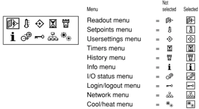
Menu
Not selected Selected Readout menu
Setpoints menu Usersettings menu Timers menu History menu Info menu I/O status menu Login/logout menu Network menu Cool/heat menu
=
=
=
=
=
=
=
=
=
= º Ò Â µ
®
† Ú æ
∂ Ï
ª
∑ Å Ó
‚
™ Ÿ Æ
∆ Í
ªÒµ®
†Úæ∂Ï
Connection of a remote digital controller to the unit
For a remote digital controller a cable length of up to 500 metres between the remote digital controller and the unit is allowed. This gives the opportunity to control the unit from a considerable distance.
Refer to "Cable for remote digital controller" in the installation manual for cable specifications.
These restrictions are the same for units in a DICN configuration.
Working with the unit
This chapter deals with the everyday usage of the unit. Here, you will find how to perform routine tasks, such as:
■ "Setting the language" on page 9
■ "Switching the unit on" on page 9
■ "Consulting actual operational information" on page 9
■ "Adjusting the temperature setpoint" on page 11
■ "Resetting the unit" on page 11
Setting the language
If desired, the operating language can be changed to any of the following languages: English, German, French, Spanish or Italian.
1 Enter the Å usersettings menu. Refer to chapter "How to enter a menu" on page 8.
2 Go to the Language submenu of the Å usersettings menu using the fi and Ì keys and press the ‡ key to enter.
3 Press ‡ to change the operating language until the desired language is active.
The controller is factory set to English.
Switching the unit on
1 Press the œ key on the controller.
Depending on whether or not a remote ON/OFF switch has been configured (refer to the installation manual), the following conditions may occur.
When no remote ON/OFF switch is configured, the LED inside the œ key lights up and an initialization cycle is started. Once all the timers have reached zero, the unit starts up.
When a remote ON/OFF switch is configured, the following table applies:
2 If the water chiller does not start after a few minutes, refer to
"Troubleshooting" on page 20.
Switching the unit off
If no remote on/off switch is configured:
Press the œ key on the controller.
The LED inside the œ key goes out.
If a remote on/off switch is configured:
Press the œ key on the controller or switch the unit off using the remote on/off switch.
The LED inside the œ key goes out in the first case and starts blinking in the second case.
Switching units ON/OFF in a DICN system
If the œ key is pressed on a unit with status NORMAL or STANDBY, all other units with status NORMAL or STANDBY will be ON or OFF.
If the œ key is pressed on a unit with status DISCONNECT ON/OFF, only this unit will be ON or OFF.
Consulting actual operational information
1 Enter the readout menu. Refer to the chapter "How to enter a menu" on page 8.
The controller automatically shows the first screen of the readout menu which provides the following information:
• ¶ cooling mode
• § heating mode
• ≠ fan (H high or L low)
• ¡ low noise mode activated (only available when option OPIF is installed)
• … pump on
• …1/2 in case of dual pump control: pump 1/2 on
• ∞11/12 circuit 1 compressor 1/2 on
• ∞21/22 circuit 2 compressor 1/2 on
• ≤ alarm and last occured malfunction code (0U4 in example)
• 13$6¢ actual temperature (inlet or outlet temperature depending on active mode)
• 12$0¢ temperature setpoint (inlet or outlet temperature depending on active mode)
NOTE When a remote digital controller is connected to a stand-alone unit, the address of the remote digital controller has to be set to SUB by means of the DIP- switches on the back of the remote digital controller.
Refer to the installation manual "Setting the addresses on the remote digital controller" for setting the address.
NOTE If the password protection is set to ON, the correct password has to be given before any further action is possible.
Local key
Remote
ON/OFF switch Unit œ LED
ON ON ON ON
ON OFF OFF Flashing
OFF ON OFF OFF
OFF OFF OFF OFF
NOTE Also consult "Customization in the service menu"
chapter "Setting of the changeable inputs and outputs"
in the installation manual.
NOTE When a remote ON/OFF switch is configured, the remote ON/OFF contact for all units with status NORMAL or STANDBY of a DICN network is the contact connected to the master unit.
For units with status DISCONNECT ON/OFF, the remote contact is the contact connected to this unit.
NOTE If the user wants 1 unit to operate on his command only, this unit is to be set to DISCONNECT ON/OFF.
It is recommended not to select the master unit for this purpose. Even if the status of the master is set to DISCONNECT ON/OFF, it will still be the contact connected to the master which will switch ON/OFF the other units in NORMAL or STANDBY mode. It would therefore never be possible to only switch the master unit OFF remotely.
Switching OFF the master unit only, should in this case be done by the local ON/OFF key on the master unit.
_v¶¡
… ≤0U4
013$6¢
∞11 ∞12 ≠H 012$0¢
∞21 ∞22 ≠H
2 Press the Ì key to enter the next screen of the readout menu.
• MANUAL MODE or COOL INLSP1/2 or COOL OUTLSP1/2 or HEAT INSLP1/2 or HEAT OUTSP1/2: manual/automatic control mode operation. If the automatic control mode is selected, the controller will indicate the active temperature setpoint.
Depending on the status of the remote contact, setpoint one or setpoint two is active.
• INL WATER: actual inlet water temperature.
• OUTL WATER: actual outlet water temperature.
• AMBIENT: actual ambient temperature.
3 Press the Ì key to enter the next screen of the readout menu.
The TEMPERATURE screen of the readout menu provides information concerning the discharge temperature of the compressors (C11 and C12/C21 and C22).
4 Press the Ì key to enter the next screen of the readout menu.
The C1/C2 TEMP. READOUT screen of the readout menu provides information concerning the refrigerant temperature (REFR) and coil temperature of circuit 1/circuit 2.
5 Press the Ì key to enter the next screen of the readout menu.
The ACT. PRESSURES screen of the readout menu provides information concerning the actual pressures of circuit.
■ HP1/2: high pressure of the refrigerant in circuit 1/2. The first number stands for the pressure in bar, the second number stands for the bubble point saturation temperature in degrees Celsius.
■ LP1/2: low pressure of the refrigerant in circuit 1/2. The first number stands for the pressure in bar, the second number stands for the dew point saturation temperature in degrees Celsius.
■ LOWNOISE: at the bottom of the first screen, the status of the lownoise setting is shown (Y=active or N=not active).
6 Press the Ì key to enter the next screen of the readout menu.
The UNIT STATUS screen of the readout menu provides information concerning the status of the different circuits.
• C11and C12: actual status of circuit 1 (ON or OFF).
• C21and C22: actual status of circuit 2 (ON or OFF).
When the unit is on and a circuit is OFF, the following status information may appear.
• SAFETY ACT.: one of the circuit safety devices is activated (refer to "Troubleshooting" on page 20).
• FREEZEUP DIS: the compressor is disabled by the freeze-up disable function.
• FREEZEUP PR: freeze-up prevention is active.
• DEFROST BUSY: defrost is active on this circuit.
• COMP PR: compressor protection function is active.
• HP SETBACK: high pressure setback is active.
• MIN.RUN.TIM: minimum running time of the compressor is active.
• LIMIT: the compressor is limited by the limitation function.
• STANDBY DICN: when in a DICN configuration, the unit is in stand by mode because there is sufficient current capacity to maintain set point.
• UNIT OFF: the unit is switched off.
• AREC INLET: the compressor will not start up when the inlet water temperature has not risen enough compared to previous switch off of the compressor.
• FREE COOLING: free cooling mode is active
• TIMER BUSY: the actual value of one of the compressor timers is not zero (refer to "Timers menu Ó" on page 13).
• PUMPLEAD TIM: the compressor will wait to start up for as long as the pump lead timer is counting down.
• NO FLOW: there is no flow after pumplead, the unit is in stand-by mode.
• NO PRIORITY: This compressor will not start up because it has no priority. Refer to "Defining the lead-lag settings" on page 16 for adjusting the priority.
• CAN STARTUP: the circuit is ready to start up when extra cooling or heating load is needed.
• When none of the above mentioned messages appears, no special functions are active and the compressor is running.
The preceding messages are written down in order of priority.
The UNIT CAPACITY is written down on the bottom of the first screen.
7 Press the Ì key to enter the next screen of the readout menu.
The EXTRA READOUT screens of the readout menu are providing the following information:
• CURRENT: actual current, measured in Ampere (A) (only when OP57 is installed)
• VOLTAGE: actual voltage (V) (only when OP57 is installed)
• RH11/12/21/22: actual running hours (h)
• C11/12/21/22C: actual running hours in cooling mode
• C11/12/21/22H: actual running hours in heating mode
• CS11/12/21/22: number of compressor start-ups
• RHP1/2: actual running hours (h) of the pump 1 or 2 8 Press the fi key to return to the other readout menus.
Selecting cooling or heating operation
The "cooling/heating" menu allows the user to set the unit in cooling, or heating operation.
The COOLING/HEATING menu provides information concerning the selected mode:
■ COOLING: cooling mode. The two cooling setpoints for both inlet water temperature control and outlet water temperature control can be used.
■ HEATING: heating mode. The two heating setpoints for both inlet water temperature control and outlet water temperature control can be used.
To define cooling/heating operation, proceed as follows:
1 Enter the cooling/heating menu. Refer to the chapter "How to enter a menu" on page 8.
If the controller is already in the cooling/heating menu, position the cursor in the upper left corner of the actual screen using the K key.
2 Position the cursor behind MODE using the K key.
3 Select the appropriate setting using the h and g keys.
4 Press K to confirm the selection.
The cursor returns to the upper left corner of the screen.
NOTE For a DICN system, the INLET WATER and OUTLET WATER values are the values of the individual units, not of the system. Temperatures of the system can be consulted in the first screen of the network menu.
NOTE When COOLING or HEATING is selected on a unit in a DICN system, this mode is transferred to all other units.
NOTE When a remote cool/heat switch is configured, the cooling/heating mode is based on the switch status. In this case the cooling mode or heating mode can not be modified in the cooling/heating menu.
Adjusting the temperature setpoint
The unit provides definition and selection of four independent temperature setpoints. Two setpoints are reserved for inlet control, the other two are reserved for outlet control.
■ COOL. INLSP1: cooling inlet water temperature, setpoint 1,
■ COOL. INLSP2: cooling inlet water temperature, setpoint 2.
■ COOL. OUTSP1: cooling outlet water temperature, setpoint 1,
■ COOL. OUTSP2: cooling outlet water temperature, setpoint 2.
■ HEAT. INLSP1: heating inlet water temperature, setpoint 1,
■ HEAT. INLSP2: heating inlet water temperature, setpoint 2.
■ HEAT. OUTSP1: heating outlet water temperature, setpoint 1,
■ HEAT. OUTSP2: heating outlet water temperature, setpoint 2.
The selection between setpoint 1 and 2 is done by a remote dual setpoint switch (to be installed by the customer). The actual active setpoint can be consulted in the readout menu.
If the manual control mode is selected (refer to "Usersettings menu Å" on page 12), none of the above-mentioned setpoints will be active.
To adjust a setpoint, proceed as follows:
1 Enter the setpoints menu. Refer to the chapter "How to enter a menu" on page 8.
If the user password is disabled for setpoint modifications (refer to "Usersettings menu Å" on page 12), the controller will immediately enter the setpoints menu.
If the user password is enabled for setpoint modifications, enter the correct code using the fi and Ì keys (refer to "User password menu Æ" on page 15). Press ‡ to confirm the password and to enter the setpoints menu.
2 Select the setpoint to be adjusted using the ‡ key.
A setpoint is selected when the cursor is blinking behind the setpoint's name.
The ">" sign indicates the actual active temperature setpoint.
3 Press the fi and Ì keys to adjust the temperature setting.
The default, limit and step values for the cooling temperature setpoints are:
4 Press ‡ to save the adjusted temperature setpoint.
When the setting has been confirmed, the cursor switches to the next setpoint.
5 To adjust other setpoints, repeat from step 2.
Resetting the unit
The units are equipped with three kinds of safety devices: unit safeties, circuit safeties and network safeties.
When a unit or circuit safety occurs, the compressor is shut down.
The safeties menu will indicate which safety is activated. The UNIT STATUS screen of the readout menu will indicate OFF - SAFETY ACTIVE. The red LED inside the π key lights up and the buzzer inside the controller is activated.
When a network safety occurs in a DICN configuration, the slaves not detected by the network will function as stand alone units.
■ If a slave unit can not be found by the network, the red light inside the π key of the master lights up and the buzzer inside the control is activated.
■ If the master can not be found by the network, the red light inside the π key of all the slaves light up and the buzzer inside their controls are activated. All units will work as stand alone units.
If the unit has been shut down due to a power failure, it will carry out an autoreset and restart automatically when the electrical power is restored.
To reset the unit, proceed as follows:
1 Press the π key to acknowledge the alarm.
The buzzer is deactivated.
The controller automatically switches to the corresponding screen of the safeties menu: unit safety or circuit safety or network safety.
2 Find the cause of shutdown and correct.
Refer to "Listing activated safeties and checking the unit status"
on page 18 and "Troubleshooting" on page 20.
When a safety can be reset, the LED under the π key starts blinking.
3 Press the π key to reset the safeties that are no longer active.
If required, enter the USER PASSWORD or the SERVICE PASSWORD. (Refer to the installation manual "Setting the password for safety reset".)
Once all safety devices are deactivated and reset, the LED under the π key goes out. If one of the safeties is still active, the LED under the π key goes on again. In this case, return to step 2.
4 It will only be necessary to switch the œ key on again if a unit safety occurs.
NOTE The customer is also allowed to define a setpoint in function of an analogue input.
NOTE Refer to "Customization in the service menu" chapter
"Setting of the changeable inputs and outputs" in the installation manual
COOLING INLET SETP COOLING OUTLET SETP
default value 12¢ 7¢
limit values(*)
(*) For glycol treated units with OPZH installed, the lower limit of the cooling temperature setpoint can be adapted by changing the minimum operating temperature in the service menu (refer to the installation manual).
7 ➞ 23¢ 5 ➞ 20¢
step value 0$1¢ 0$1¢
HEATING INLET SETP HEATING OUTLET SETP
default value 40¢ 45¢
limit values(*) 20 ➞ 45¢ 25 ➞ 50¢
step value 0$1¢ 0$1¢
NOTE When a setpoint on a unit in a DICN system is set, this setpoint will be transferred to all other units.
NOTE Also consult "Defining the floating setpoint settings" on page 16.
If the user shuts down the power supply in order to repair a safety, the safety will automatically be reset after power-up.
NOTE The history information, i.e. the number of times a unit safety or a circuit safety occurred and the unit status at the moment of shutdown, can be checked by means of the history menu.
Advanced features of the digital controller
This chapter gives an overview and a brief functional description of the screens provided by the different menus. In the following chapter, you will find how you can set up and configure the unit using the various menu functions.
All menus are directly accessible using the corresponding key on the digital controller or through the main menu (refer to "How to enter a menu" on page 8). The down arrow v on the display indicates that you can go to the next screen of the current menu using the Ì key.
The up arrow ^ on the display indicates that you can go to the previous screen of the current menu using the fi key. If ÷ is displayed, this indicates that you can either return to the previous screen or can go to the next screen.
Readout menu ª
Setpoints menu ∑
Depending upon the settings in the "advanced" usersettings menu, the "setpoints" menu can either be entered directly or by means of the user password.
Usersettings menu Å
The "usersettings" menu, protected by the user password, allows a full customization of the units.
THERMOSTAT
COMPRESSOR
FAN To consult actual operational informa-
tion about the status of the pump, the compressor and the fans and the temperature setpoint (depending on active mode).
To consult actual operational informa- tion about the control mode, the inlet and outlet water temperature.
Note that for a DICN system, the INLET WATER and OUTLET WATER values are the values of the individual units, not of the system. Temperatures of the system can be consulted in the first screen of the network menu.
To consult information about the discharge temperature of circuit 1.
To consult information about the discharge temperature of circuit 2 (only for EWYQ130~250).
To consult information about the temperature of the refrigerant and coils of circuit 1.
To consult information about the temperature of the refrigerant and coils of circuit 2 (only for EWYQ130~250).
To consult information about the actual pressures and the fans of circuit 1 and to check if the fans are running in lownoise mode.
To consult information about the actual pressures and the fans of circuit 2 (only for EWYQ130~250).
To consult information about the unit status of circuit 1 and the capacity of the unit.
To consult information about the unit status of circuit 2 (only for EWYQ130~250).
To consult actual operational informa- tion about the current (Ampere) and voltage of the unit.
_v¶
… ≤0U4
013$6¢
∞11 ∞12 ≠H 012$0¢
∞21 ∞22 ≠H
_÷COOL. INLSP1:012$0¢
INLET WATER:013$6¢
OUTLET WATER:007$0¢
AMBIENT:006$5¢
_÷ C1 TEMP.READOUT C11 DISCHARGE:010$1¢
C12 DISCHARGE:010$5¢
_÷ C2 TEMP.READOUT C21 DISCHARGE:010$1¢
C22 DISCHARGE:010$5¢
_÷ C1 TEMP.READOUT C1 REFR:000$0¢
C11 COIL:000$0¢
C12 COIL:000$0¢
_÷ C2 TEMP.READOUT C2 REFR:000$0¢
C21 COIL:000$0¢
C22 COIL:000$0¢
_÷ C1 ACT. PRESSURES HP1:019$0b = 050$8¢
LP1:000$4b = -05$2¢
FAN1:OFF
_÷ C2 ACT. PRESSURES HP2:019$0b = 050$8¢
LP2:000$4b = -05$2¢
FAN2:OFF
_÷ UNIT STATUS C11:OFF SAFETY ACT.
C12:OFF SAFETY ACT.
UNIT CAPACITY:000%
_÷ UNIT STATUS C21:OFF SAFETY ACT.
C22:OFF SAFETY ACT.
_÷ EXTRA READOUT CURRENT:055A VOLTAGE:023V
To consult actual operational informa- tion about the total running hours, total running hours in cooling and in heating mode and the number of compressor stops of circuit 1 (first screen) and total running hours of the pumps.
To consult actual operational informa- tion about the total running hours, total running hours in cooling and in heating mode and the number of compressor stops of circuit 1 (second screen).
To consult actual operational informa- tion about the total running hours, total running hours in cooling and in heating mode and the number of compressor stops of circuit 2 (first screen) (only for EWYQ130~250).
To consult actual operational informa- tion about the total running hours and the number of compressor stops of circuit 2 (second screen) (only for EWYQ130~250).
To define the temperature setpoints.
Use the fi and Ì keys to scroll through the menu and press the ‡ key to enter the submenu of your choice.
To define the thermostat settings.
To define the settings for manual control.
To define the compressor lead-lag settings.
To define the compressor capacity limitation settings.
To define the action on all the fans in case the unit is off.
_÷ EXTRA READOUT C11RH:00000hCS:00000 C11C:00000h H:00000h RHP1:00001hP2:00000h
_÷ EXTRA READOUT C12RH:00000hCS:00000 C12C:00000h H:00000h
_÷ EXTRA READOUT C21RH:00000hCS:00000 C21C:00000h H:00000h
_÷ EXTRA READOUT C22RH:00000hCS:00000 C22C:00000h H:00000h
> COOL. INLSP1:012$0¢
COOL. INLSP2:012$0¢
COOL. OUTSP1:007$0¢
COOL. OUTSP2:007$0¢
USERSETTINGS MENU
>THERMOSTAT COMPRESSOR FAN PUMP
FLOATING SETPOINT LANGUAGE
TIME AND DATE FREE COOLING DICN ADVANCED DEFROST SERVICE MENU
_v THERMOSTAT MODE:INL WATER LOADUP:300s-DWN:030s
_^ MANUAL SETTINGS C11:OFF C12:OFF C21:OFF C22:OFF F1*:OFF F2*:OFF
_v COMPR.LEAD-LAG MODE:PRIORITY PRIORITY:
C11>C12>C21>C22
_^ COMPR.CAP.LIMIT MODE:LIMIT SETTING SET: C11:OFF C12:OFF C21:OFF C22:OFF
_ FAN FORCED ON IF UNIT IS OFF THEN ALL FANS:OFF