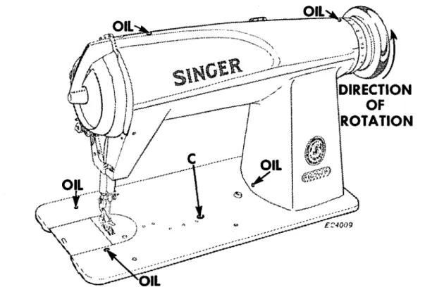
A reservoir in the machine's bearing supplies oil to the race of the sycrog and to the bearings and eccentrics on the hook drive shaft (except the rear ball bearing). Release the latch, turn the open end of the bobbin case down and the bobbin will drop out. Then wind the end of the thread around the bobbin a few times in the direction shown in fig.
Hold the coil between the thumb and forefinger of the right hand, as shown in Fig. Then pull the thread into the slot on the end of the bobbin case as shown in Fig. 8; draw the thread under the tension spring and into the delivery eye at the end of the tension spring.
5 of the coil holder; release the latch and push the spool housing back until. The pressure of the presser foot on the material is regulated by the screw N, fig. 20, when the tip of the needle reaches the neck plate on the downward stroke of the needle bar.
22 on the needle bar should only be visible on the lower edge of the needle bar clutch F2, Fig.
CASE
TO SET THE NEEDLE SHOULDER AT THE CORRECT HEIGHT IF THE NEEDLE BUSH REVIEW TIP. Place the needle bar when it is at the end of its stroke so that the needle hole is over the needle guard of the needle box holder enough to allow clearance for the thread, as shown in Fig. Remove the presser foot, slide plate, plate throat, bobbin case, feed dog and bobbin case holder position finger.
Turn the bobbin case about half a turn so that it is clear of the needle. The tip of the hook should pass the needle as close as possible without actually touching it. The function of the needle guard Fig. 28 of the bobbin holder is to prevent the hook tip from contacting the needle with the loop take-up time in case the needle is bent sideways. point to the hook point.
When the needle guard is positioned correctly in relation to the needle, it will deflect the needle slightly to the left as the needle approaches its lowest position. The clearance between the positioning finger and the bobbin case holder should be just sufficient. When it is necessary to create more space for the needle, remove the bobbin case holder from the hook and remove a small amount of metal from the needle guard, using a 1/8 inch strip of very fine emery cloth (approx. . #320), while holding one. end of the emery.
HOOK POINT
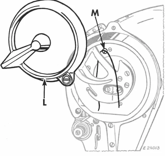
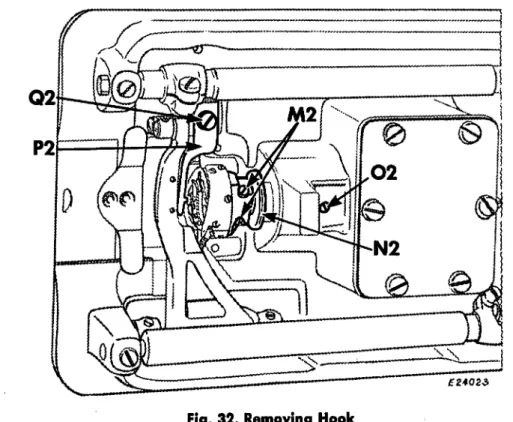
Loosen the two setscrews at M2 in the hub of the hook and then turn the machine pulley away from you. When installing a new sewing hook on the spindle, make sure that the hook thread protector T2 is at the bottom and the bobbin case holder U2 is in the position shown in the figure. Turn the bobbin case holder U2 until the notch 52 is at the top. Then, replace the bobbin case holder positioning bracket, making sure that the positioning finger fits into the notch at the top of the bobbin case holder, as shown in Fig.
34 can be moved end-wise enough to control the end play of the hook shaft before tightening the two screws X2, Fig. When replacing this unit in the machine, make sure the set screw enters the spline in the bottom of the bushing. The hook drive shaft bushing will be posted correctly. sitiC?ne~ when end play has been removed from the shaft by placing the bushing against the hub of the internal gear.
The J3 collar should normally be flush with the end of the eccentric body hub. To remove all end play from the shaft, lightly tighten the set screws in the machine pulley and while holding the needle bar crank in place, tap the machine pulley into place with the palm of the hand; Then tighten the screws securely. -the two shafts, in this position, guide the belt to the bottom pulley at the point furthest from you and then, turning the machine pulley away from you, slide the belt across the rest of the width of the bottom pulley.
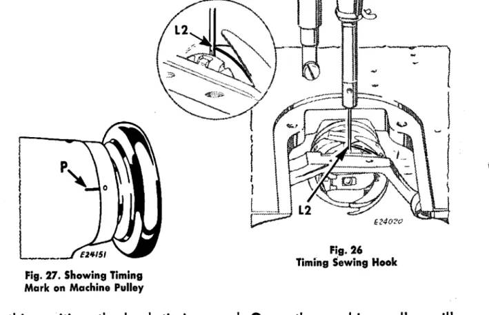
Check the timing of the machine before you start sewing; see page 16, and if necessary, loosen the set screws in the lower pulley to bring ·the upper and lower shafts into exact time. The armature must be removed from the face plate side of the machine and under no circumstances should any attempt be made to separate the needle bar crank from the shaft as it is manufactured as a unit for accuracy. Remove the needle rod crank bolt Z, Fig. 21 by loosening the two set screws, reached through hole R, Fig.
To remove the needle bar link, drop it to its lowest position, pull. forward from the guide block, turn at right angles, then pull upwards and outwards. Care must be taken to see that no foreign objects enter these bearings when they are handled from the machine. The ball bearings on the front of the arm, and the rear of the hook drive shaft are forced into their correct position at the factory and should not be removed except for replacement.
PARTS LIST
MACHINE 600W1
201537E Rotary pick-up guard spring lock washer nut 350503X Rotary pick-up guard spring catch screw.
TO ALL WHOM IT MAY CONCERN
SINGER* PARTS AND NEEDLES IN SINGER MACI-IINES