CATALOG NO.
WH398M
First Edition
STYLES
398-21 398-22 398-23 398-24 398-25 398-26 398-27 398-28 398-29
Adjusting instructions and illustrated parts list
—
ii
U
398 Classic Series
-Safety stitch machines with Pushbutton stitch length change
I
Finest Quality Zua
EquipmentCATALOG NO. WH398M ADJUSTING INSTRUCTIONS AND
ILLUSTRATED PARTS LIST FOR
398 CLASSIC SERIES - SAFETY STITCH MACHINES WITH
PUSHBUTTON STITCH LENGTH CHANGE
STYLES
398-21 398-24 398-27
398-22 398-25 398-28
398-23 398-26 398-29
First Edition Copyright 1982
By
Union Special Corporation Rights Reserved in All Countries
Printed in U.S.A.
July, 1982
CLASS DESCRIPTION
Small frame, high speed, high capacity, differential feed, vertical needle, Safety Stitch machines. The needle drive mechanism moves two straight needles in a vertical plane. Two independent rows of stitching are produced - “Double-Lock” stitch at the left needle and two or three thread overseaming stitch at the right needle. Machines include fabric trimming mechanism, adjustable looper avoid motion, fully enclosed automatic lubrication.
TECHNICAL DATA STITCH AND
SEAM TYPE
Specification 516-SSa-2
Spreader furnished for conversion to Specification 515—SSa-2
FEED SYSTEM
Main and differential feed mechanisms.
Push button stitch length adjustment with independent thumbscrew control for
differential feed
MAXIMUM SPEED 5500 R.P.M.
(Depending on operation) LUBRICATION
Enclosed automatic splash system with oil return pump
NEEDLE GAUGE See machine styles
(Seam width)
NEEDLE GAUGE EXPLANATION. Example: On Style 398-27 the 12 3/16 is gauge of machine.
The 12 indicates the distance between needles graduated inis 12/64 or 3/16 inch between needles. The fraction 3/16 represents1/64 increments, thus 12the width of overedge seam. The total seam width is the sum of the two figures, i.e., 3/16 + 3/16 or total seam width of 3/8 inch.
MACHINE STYLES
398-21 (8-1/8 Ga.) For seaming light to medium weight fabrics. Short, narrow presser foot with matiching feeds and throat plate allow stitching on short radius curves. Typical application - setting sleeves and side seaming work shirts, robes and pajamas.
398-22 (8-3/16 Ga.)
398-23 (12-3/16 Ga.)fabric. Design of sewing parts allows machine to be used on a variety of garGeneral purpose machine for seaming light to heavy weight ments ranging from shirts and blouses to women’s sportwear and jackets.
398-24 (8-3/16 Ga.) Same as Style 398-22 except fitted with narrow tractor type presser foot and related sewing parts for crossing heavy seams.
398-25 Same as Style 398—24 except 12—3/16 gauge.
398-26 (5-1/8 Ga.)
398-27 (12-3/16 Ga.)women’s sportwear.tion - assembling and seaming operations on jeans, work clothing, jacketsFor seaming medium to heavy weight fabrics. Typical applicaand
MACHINE STYLES (Continued)
398-28 Same as Style 398-27 except fitted with tractor type presser foot and related sewing parts for crossing heavy seams.
398-29 Same as Style 398-21 except 12-3/16 gauge.
NOTE: All machine styles listed can be furnished with “AIR-KLIPP’ vacuum type chain cutter.
IDENTIFICATION OF MACHINES
Each UNION SPECIAL machine carries a style number, which on this class machine is stamped in the style plate located to the right rear of machine.
The serial number is stamped on extension of casting at right rear base of machi ne.
LUBRICATION
Oil capacity of Class 398 is eight ounces. Use a straight mineral oil with a Saybolt viscosity of 90 to 125 seconds at 100 degrees F. This is equivalent to Union Special Corporation Specification No. 175.
Machine is filled with oil at spring cap under top cover or at oil filler screw between tension disc support and top cover. Before operating, check oil level at sight gauge on front of machine. When proper oil level is reached, red bulb on oil level indicator will register between red gauge lines.
To drain oil remove magnetic plug on back of machine near bottom edge of base.
Clean magnetic plug of any metallic material that may have accumulated in crankcase.
Oil must be changed periodically to minimize wear.
THREADING
Be sure machine is threaded properly according to threading diagram Fig. 1, for five thread machines or Fig. 1A, for four thread machines.
THREADING DIAGRAMS
Before threading machine; unlock presser foot release bushing,swing presser arm and cloth plate out of position; pull upper looper thread tube up for five threads.
Turn handwheel in operating direction until needles are at highest position. Thread tweezers No. 660-272 and threading wire No. 39899 A are furnished with machine to aid in threading.
Thread machine in sequence as shown in Fig. 1; (1) lower overedge looper thread, (2) 401 looper thread, (3) upper overedge looper thread, (4) rear needle thread and (5) front needle thread. Push upper looper thread tube down.
Thread machine in sequence as shown in Fig. 1A; (1) overedge looper thread, (2) 401 looper thread, (3) rear needle thread and (4) front needle thread.
Fig. 1
TUBE UP
TURN TO RELEASE PRESSER ARM
Fig. 1A
--
ADJUSTING iNSTRUCTIONS NOTE: Instructions stating direction or
location, such as right, left, front or rear of machine; are given relat ive to operator’s position at the machine. The handwheel rotates clockwise, in operating direction;
when viewed from the right end of machine.
EXAMINE NEEDLES TO ASSURE PROPER TYPE AND SIZE ARE BEING USED (EXAMPLE:
120 GS-090/036). THE FOLLOWING CHECKS RE LATED TO NEEDLES ARE IMPORTANT FOR SUCCESS FUL OPERATION. IMMEDIATELY REPLACE AND DIS CARD DEFECTIVE NEEDLES.
- Roll the needle over a flat surface to check straightness. If the needle is bent it will wobble; as shown (A, Fig. 2).
- Use the thumbnail test to check for bluntness as shown (B, Fig. 2).
- Check for any sharpness around the eye and grooves of the bottom of the eye! Seesaw the thread through for a quick sharp it will cut the thread; as shown (C, Fig. 2).
- Make sure the needles are all the way up in needle holder with the spot or scarf to the rear; as shown (D, Fig. 2).
Machines shipped from the factory are sewn off using needles listed:
Machine Style Type and Size
398-21, 398-22, 398-23, 398-24, 398-25, 398-26, 398-29 120 GS-090/036 398-27, 398-28
120 GAS-125/049 making adjustments involving the needles, loopers or needle guards, use new needles of correct type and size.
SEE FOLLOWING CHART FOR DESCRIPTIONS AND SIZES OF NEEDLES AVAILABLE FOR CLASS 398 MACHINES.
____________
Description
_______________
Round shank, round point, set point, extra 080/032, short, double groove, struck groove, ball 100/040, eye, spotted, rounded scarf, with 3/64 125/049, inch (1.2mm) radius at scarf, chromium
plated.
Same as Type 120 GS except it has a modi- 110/044, 125/049, fled point
140-/054.
Fig. 2
and hooks on the tip of the needle;
needle. Don’t forget the check. If the eye is and positioned correctly
NOTE: Before always
Needle Type 120 GS
120 GAS
Size Available 075/029,
090/036, 110/044, 140/054.
Needle Type Description Sizes Available 120 GFS Same as Type 120 GS except it has a reduced 110/044, 125/049.
eye and groove,
120 GHS Same as Type 120 GS except it has a thin ball 075/029, 080/032,
point. 090/036, 100/040,
110/044, 125/049, 140/054.
120 GKS Same as Type 120 GHS except it has an over- 075/029, 080/032,
size ball eye. 090/036, 100/040,
110/044.
To have needle orders promptly and accura tely filled, an empty package, a sample needle, or type and size number should be forwarded.Use description on label. A complete order would read: “1000 Needles, Type 120 GS,Size 090/036”.
NEEDLE REPLACEMENT
To replace needles, turn handwheel in oper ating direction until needles reach highest position. Rotate presser foot release lever (A, Fig. 3) counterclockwise and swing presser foot (B) to the left. Loosen screws (C) and remove needles. Insert new needles against stop in holder with scarf of needle positioned to the rear; tighten screws (C). Swing presser foot (B) into position and lock presser foot release lever (A).
NEEDLE ALIGNMENT
Needle must center in needle slots of
throat plate (left to right) as shown in Fig.4.
If adjustment is required, loosen screws (A, Fig. 5) and needle lever binder screw
(A, Fig. 6). Align needles to center in throat plate needle slots by turning eccentric needle head guide bar (B, Fig. 5). Position needle lever to left or right on its cross shaft to correspond with the repositioning of eccentric guide bar. Manually move needle head (C) up and down several times to ensure that the
needle lever aligns with the needle head.Tight en screws (A). Temporarily tighten screw
(A, Fig. 6) and proceed to needle height ad justment.
NEEDLES ARE CENTERED LEFT TO RIGHT
Fig. 4
—C
Fig. 5
NEEDLE HEIGHT
Rotate handwheel in operating direction until needles are at highest position. Speci fied height is 17/32 inch (13.5mm) from point (tip) of needles to top of throat plate as shown in Fig. 7.
If adjustment is required, loosen binder screw (A, Fig. 6) and position needle lever
(B) up or down as required to attain specifi ed dimension. Tighten screw (A, Fig. 6). Ro tate handwheel in operating direction and check for binds in needle head assembly.
Should a bind exist, refer to NEEDLE ALIGN MENT.
Needle height gauge No. 21227 DD can be used by placing it on top of throat plate and rotate handwheel to bring needle head down so its bottom rests on proper step of gauge AT BOTTOM OF DOWNSTROKE. You will note two levels on gauge; upper step is for these machines re quiring 17/32 inch (13.5mm) needle height, while the lower step is used for other machine
styles requiring a 7/16 inch (11.1mm) setting.
PRIOR TO MAKING THE FOLLOWING ADJUSTMENTS, RE MOVE CLOTH PLATE, FABRIC GUARD, CHIP GUARD, UPPER KNIFE, LOWER KNIFE,MAIN AND DIFFERENTIAL FEEDS.
CLOTH PLATE
To remove cloth plate (A, Fig. 8) loosen screw (B) and lift upward with stud (C) and screw (D) assembled.
Before replacing, tighten screw (D) while holding stud (C)until all end play is removed.
Cloth plate must be allowed to swing open, so do not over tighten screw (D). Assemble cloth plate to machine by inserting stud (C) with flat and “V’ notch to rear, into hole in bed casting. Tighten screw (B) to press “V’ notch of stud (C) against screw (D). This locks screw CD) and stud (C) in position and allows cloth plate to swing open.
Fig. 6
lTII
I
17/32 inch • •
(13.5mm)
1
Fig. 7
Fig. 8
LOWER OVEREDGE LOOPER
PRIOR TO CHECKING LOOPER ADJUSTMENT, REMOVE FRONT AND REAR NEEDLE GUARDS.
LOOPER GAUGE - With looper (A, Fig. 9) at ex treme left position, distance from looper point to centerline of rear needle should be 3/32 inch (2.4mm) as shown in Fig. 9.
PRIOR TO ADJUSTING LOOPER, POSITION UPPER LOOPER/SPREADER UP AND AWAY FROM LOWER LOOPER.
Rotate handwheel to position looper at ex treme right end of travel and loosen clamp nut (B, Fig. 9). Rotate handwheel to position looper at extreme left end of travel and set looper gauge by adjusting looper in or out of looper shaft (C). Rotate handwheel and po sition looper into scarf of rear needle and set looper point to touch but NOT deflect needle. Tighten clamp nut (B) securely and recheck looper gauge.
REAR OVEREDGE NEEDLE GUARD
Remove spring from inside of lower knife holder (A, Fig. 10) and assemble lower knife holder into throat plate support block. Re place rear needle guard (B) using screw (C) with front edge of guard centered in slot of
knife holder (A) as shown. Tighten screw (C) temporarily to hold guard in position yet allows it to be moved. Rotate handwheel in operating direction so the lower overedge looper (D) moves from the extreme left po sition into the scarf of rear needle. Move guard (B) forward until the front guarding surface contacts the needle but does NOT de flect it. Set guard as low as possible so that it will not interfere with needle thread as loop is formed to rear of needle. Tighten screw (C) securely. Guard should not inter fere with lower knife holder movement or con tact lower overedge looper at any point.
FRONT OVEREDGE NEEDLE GUARD
Assemble front overedge needle guard (E, Fig. 10) to throat plate support using screw (F). Rotate handwheel in operating direction to position needle at bottom of stroke. Set guard to needle with minimum clearance - approximately .004 inch (.10mm).
Tighten screw (F) securely. DO NOT PINCH NEEDLE BETWEEN FRONT AND REAR GUARDS.
Fig. 9
Fig. 10
Fig. 11
OVEREDGE UPPER LOOPER AND/OR SPREADER NOTE: When using needle sizes 075/029 throuqh
100/040 fit machine with upper looper No. 39808 A. Looper No. 39808 C is re commended for use with needle sizes 110/044 through 140/054.
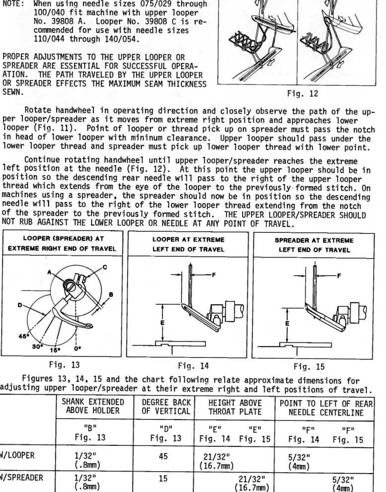
PROPER ADJUSTMENTS TO THE UPPER LOOPER OR SPREADER ARE ESSENTIAL FOR SUCCESSFUL OPERA ATION. THE PATH TRAVELED BY THE UPPER LOOPER OR SPREADER EFFECTS THE MAXIMUM SEAM THICKNESS SEWN.
Rotate handwheel in operating direction and closely observe the path of the up per looper/spreader as it moves from extreme right position and approaches lower looper (Fig. 11). Point of looper or thread pick up on spreader must pass the notch in head of lower looper with mininum clearance. Upper looper should pass under the lower looper thread and spreader must pick up lower looper thread with lower point.
Continue rotating handwheel until upper looper/spreader reaches the extreme left position at the needle (Fig. 12). At this point the upper looper should be in position so the descending rear needle will pass to the right of the upper looper thread which extends from the eye of the looper to the previouslyformed stitch. On machines using a spreader, the spreader should now be in position so the descending needle will pass to the right of the lower looper thread extending from the notch of the spreader to the previously formed stitch. THE UPPER LOOPER/SPREADER SHOULD NOT RUB AGAINST THE LOWER LOOPER OR NEEDLE AT ANY POINT OF TRAVEL.
LOOPER (SPREADER) AT EXTREME RIGHT END OF TRAVEL
Fig. 15
Figures 13, 14, 15 and the chart following relate approximate dimensions for adjusting upper looper/spreader at their extreme right and left positions of travel
SHANK EXTENDED DEGREE BACK HEIGHT ABOVE POINT TO LEFT OF REAR ABOVE HOLDER OF VERTICAL THROAT PLATE NEEDLE CENTERLINE
‘‘B’’ ‘‘E’’ ‘‘F’’ ‘‘F’’
Fig. 13 Fig. 13 Fig. 14 Fig. 15 Fig. 14 Fig. 15
W/LOOPER 1/32” 45 21/32” 5/32”
(.8mm) (1.6.7mm) (4mm)
W/SPREADER 1/32” 15 21/32” 5/32”
(.8mm) (16.7mm) (4mm)
Fig. 12
LOOPER AT EXTREME LEFT END OF TRAVEL
-F SPREADER AT EXTREME
LEFT END OF TRAVEL
Fig. 13 Fig. 14
To adjust upper looper/spreader, follow instructions in sequence as follows:
1. Position upper looper/spreader at the right end of travel, loosen clamp screw (A, Fig. 13) and set looper/spreader shank to diniension ‘B’ above holder.
Tighten screw (A) lightly.
2. With upper looper/spreader still positioned at the right end of travel, loosen screw (C) and rotate holder to align shank of looper/spreader to the specified line in castin9 denoting 15, 30 or 45 decirees back of vertical (location “D”).
Tighten screw (C) liqhtly.
3. Rotate handwheel in operating direction bringing the upper looper/spreader into the LOWER looper. The POINT of upper looper or THREAD PICK-UP of upper spreader should be set to enter the notched area behind the head of the lower looper - See Fig. 11.
4. Continue to rotate handwheel in operating direction until upp’ér looper/spreader is at extreme LEFT end of travel. Rotate upper looper/spreader holder as re quired to position POINT of upper looper to dimension “E”, Fig. 14 or LOWER POINT of upper spreader to dimension “E”, Fig. 15 from top of throat plate.
5. With upper looper/spreader still positioned at left end of travel, it may be necessary to move looper/spreader holder in or out of its shaft to set POINT of looper dimension “F”, Fig. 14 or LOWER POINT of spreader dimension “F”, Fig. 15 which is to the left of centerline of rear needle. Rotate handwheel to position upper looper/spreader to the right end of travel before tightening screw
(C, Fig. 13) securely. Tighten screw (A).
6. If the needle(s) are beina deflected by the upper looper/spreader, clearance to the needle can be increased by reducing the length of looper/spreader shank above holder (dimension “B”), See Step 1. It will then be necessary to slightly reduce the angle of the shank back of vertical, See Step 2. Set looper/spreader to lower looper, See Step 3. Reversing this procedure will position the looper!
spreader closer to the needle.
401 STITCH LOOPER ADJUSTMENTS
PRIOR TO CHECKING LOOPER REMOVE FRONT NEEDLE GUARD AND REAR NEEDLE GUARD OUT OF POSITION.
Loosen screw (A, Fig. 16) and push
looper down so that its shank rests on shaft.
Rock looper blade to front and rear while tightening clamp screw (A). This will ensure the clamp screw is securing looper on flat surface of looper shank.
With looper to extreme right, loosen binder screw (B, Fig. 16). Position looper Fig. 16 holder right or left so the point of looper
is 3/32 inch (2.4mm) from centerline of front needle as shown in Fig. 16. Turn handwheel in operating direction until point of looper enters scarf on back side of needle. Move looper blade forward until it touches but does NOT deflect needle. Tighten binder screw (B).
To form stitch type 401, the looper mov ing to the left passes to rear of needle and enters the thread loop formed as needle rises (A, Fig. 17). Traveling to the right, looper passes to front of descending needle which enters a triangle formed by the looper thread, blade of looper and needle loop around looper blade (B).
This front to rear movement of looper is termed “AVOID MOTION”. Avoid motion of the looper occurs in unison with its right and left travel. As a result, the looper point travels in an elliptical path as shown in Fig. 17.
Minimum clearance between needle and looper at functions shown in Fig. 17 must be maintained. The descending needle (B) may contact the looper blade lightly. Too much clearance or needle deflection at A or B can cause skipped stitches, broken needles, etc..
The looper avoid motion on these machines can be adjusted to obtain proper conditions for various size needles used.
ECCENTRIC SETTING NEEDLE RANGE BY SIZE S - SMALL
M - MEDIUM L - LARGE
075/029, 080/032, 090/036 080/032, 090/036, 100/040 110/044, 125/049, 140/054
Loosen nut (A, Fig. 18). Rotate handwheel until needles are at lowest position.
Align proper mark 5, M or L on stud (B) to timing mark on link (C). Torque nut (A) to 25 in. lbs. (29 cm/kg). Re-check 401 looper setting, then replace bottom cover and torque cover mounting screws to 19—21 in. lbs. (22—24 cm/kg). Fill machine with oil to proper level.
NOTE: If needed, stud (B) can be positioned to timing mark at any point between 5, M or L to obtain proper amount of looper avoid. Check clearance between 401 looper and needle following any adjustment to the looper avoid setting.
LOOPER AVOID ADJUSTMENT
C
NEEDLE OF FEEDDIRECTIONPATH LOOPER POINT TRAVFLS AROUND NEEDLE
Fig. 17
Fig. 18 Should conditions described previously indi
cate adjustments are required; drain the oil and remove bottom cover from machine.The
“S”, “M” or “L” marked on eccentric stud are aligned to the timing mark on looper a void link according to the range of needle size used. SEE CHART:
— —
______________
401 STITCH REAR NEEDLE GUARD
Rear needle guard (A, Fig. 19) should prevent the looper point from striking the needle as the looper moves from the right and enters the scarf of front needle.
Rotate handwheel in operating direction so that the point of looper moving from ex treme right position enters the scarf of front needle. Loosen screw (B) and move guard for ward to touch but NOT deflect needle. Turn handwheel so needle is at lowest position.
Raise or lower guard so top of needle eye is slightly above guarding surface of rear needle guard - REAR GUARD MUST NOT INTERFERE WITH FORMATION OF THREAD LOOP FORMED AS NEEDLE RISES. Re-check guard to needle position de scribed earlier and tighten screw (B).
401 STITCH FRONT NEEDLE GUARD
With needles at lowest position, front needle guard (C, Fig. 19) is set with minimum clear ance to needle, .004 inch (.10mm). DO NOT PINCH NEEDLE BETWEEN FRONT AND REAR NEEDLE GUARDS. 401 LOOPER MUST NOT RUB GUARD.
If adjustment is required, loosen screw (D) and locknut (E). With needle at lowest position set guard (C) so it’s relatively close to the needle but NOT touching it.
Tighten screw CD). Turn screw (F) in against guard. Continue turning screw (F) to force guard slightly to the rear maintaining .004 inch (.10mm) clearance to needle. Tighten locknut (E).
MAIN AND DIFFERENTIAL FEEDS
ASSEMBLE MAIN, DIFFERENTIAL FEEDS AND THROAT PLATE TO MACHINE.
Rotate handwheel in operating direction and stop when teeth of rising feeds first appear above top surface of throat plate. The feeds should be level with the throat plate at this time. With feeds at highest point of travel, teeth should extend approximately 3/64 inch
(1.2mm) above throat plate as shown in Fig. 20.
To level feeds, loosen lock screw (A, Fig. 20) and rotate tilt adjusting pin (B) to position rear of feeds up or down. Tighten lock screw (A) securely.
Feed height is set by loosening attaching screws and moving feeds to height re quired. Retighten screws.
Fig. 19
Fig. 21
LOWER KNIFE
INSERT SPRING BACK INTO LOWER KNIFE HOLDER AND ASSEMBLE HOLDER TO THROAT PLATE SUPPORT.
Upper edge of knife (A, Fig. 21) is set even with top surface of throat plate. Positioning of the lower knife cutting edge left to right to obtain proper seam width is determined by the width of the stitch tongue of the throat plate.
If adjustment is required, loosen screw (B) and move knife up or down so its cutting
edge is even with top of throat plate. Tight- Fig. 22 en screw (B). If cutting edge of knife is
tilted, loosen screw (C) and rotate holder (D) front to rear as required. Tighten screw (C). Holder should move freely left to right and not bind with overedge rear needle guard centered in slot of knife holder shaft.
NOTE: See shear angle adjustment.
UPPER KNIFE
REMOVE NEEDLES AND RE-ASSEMBLE UPPER KNIFE HOLDER INTO ITS SLOT ON UPPER KNIFE DRIV ING ARM. ALSO REPLACE UPPER KNIFE IN ITS HOLDER AND HOLD FIRMLY IN POSITION.
At lowest position the front tip of cutting edge of upper knife should extend 1/32 inch (.8mm) below cutting edge of lower knife.
With upper knife
CE,
Fig. 21) at lowest point of travel; position front tip of its cutting edge 1/32 inch (.8mm) below cutting edge of lower knife by moving knife holder (F) left to right. Upper knife must be held firmly against lower knife dur ing this adjustment. Tighten upper knife holder screw (G) to lock upper knife in position. Assemble knife clamp (H) and chip guard (J) in position using nut (K).Set chip guard (J) against top surface of upper knife and slightly back of its cut ting edge. Tighten nut (K).
Loosen screw CL) to enable spring pressed lower knife to move freely left to right. If desired, lower knife can be locked in position by tightening screw CL) against knife holder shaft.
NOTE: Locking nut (M) must be tightened to hold screw CL) in position; screw (L) also serves as a latch pin for cloth plate. Proceed to shear angle adjust ment.
SHEAR ANGLE ADJUSTMENT
NOTE: Be sure lower and upper knives are adjusted properly before setting shear angle.
The proper shear angle between cutting edge of upper and lower knives is 1 degree as shown in Fig. 22. This results in a cutting action similar to that of a pair of scissors. Best results are obtained if both knives are sharpened correctly prior to adjusting.
If adjustment is required, loosen locknut (A, Fig. 22) and lock lower knife holder out of position away from upper knife with screw (B).
SHEAR ANGLE ADJUSTMENT (Continued) Loosen screw (C) and clamp screw (D). Ad just guide plate (E) inward to angle top front edge of lower knife slightly to the right.Hold guide plate (E) in position and tighten screw
(C) and clamping screw (D). Loosen screw (B) to allow lower knife holder to float left to right. Tighten locknut (A).
PRESSER FOOT ALIGNMENT
To align presser foot bottom, loosen clamp screw (A, Fig. 23) and unlock presser foot release lever (B), but do not raise plunger (C) from presser arm (D). Adjust presser foot front to rear so front of its needle slots align with needle slots in throat plate.
To adjust presser foot so it will lie flat on throat plate; lift presser foot and tilt its right edge up or down as required.
Tighten clamp screw (A), lock presser foot re lease lever and check alignment.
To align presser foot needle slots to throat plate needle slots left to right, loosen collar screws (A, Fig. 24) and clamp screw (B). Adjust lifter lever shaft (C) left or right as required and tighten collar screws (A). Hold lifter lever CD) up and tighten clamp screw (B).
Corpletely unlock presser foot release lever (B, Fig. 23). Plunger (C) should clear presser arm (D) without binding.
On machines equipped with a tractor type presser foot; the front edge of its 401 stitch needle slot must be 1/16 inch (1.6mm) forward of front edge of the 401 stitch needle slot in throat plate.
Lift tractor presser foot to its hightest position and tilt front of presser foot toe downward. The rear of presser foot front section must not contact needle.
PRESSER FOOT LIFT
Lift presser foot to highest position and rotate handwheel in operating direction.
Upper looper/spreader must move from extreme right to extreme left without contact ing presser foot.
If adjustment is required, loosen locknut (E, Fig. 24) and adjust stop screw (F) so presser foot will not interfere with upper looper/spreader, then tighten locknut (E).
Loosen locknut (G) and set stop screw (H) on upper end of lifter lever arm so there is approximately 1/16 inch (1.6mm) free motion in lifter lever before presser foot starts to rise, then tighten locknut (G).
Fig. 23
Fig. 24
PRESSER FOOT PRESSURE
Sufficient pressure should be maintained to D E feed work uniformly. Excessive spring press
ure will cause feeds and presser foot to wear prematurely when chaining.
\
Rotate handwheel in operating direction (1m) until both main and differential feeds are
positioned below throat plate. Loosen locknut (A, Fig. 25) and turn pressure reciulator (B) clockwise for more pressure of counterclock wise for less pressure, then tighten locknut (A).
NOTE: Adjusting pressure regulator (B) will effect the function of pressure re lease lever (C). Plunger (C, Fig. 23) should clear presser arm when pressure release lever (C, Fig. 25) is unlocked in position. When release lever (C) is locked in position, presser foot should be held firmly against throat plate. If these conditions do not exist the following adjustment must be made.
Lock presser foot in position with pressure release lever (C); loosen capnut CD) and ad just nut (E) up or down so its under surface is 1/16 inch (1.6mm) above pressure regulator (B) as shown in Fig. 25. Hold nut (E) in position and tighten capnut CD).
SETTING STITCH LENGTH
The actual stitch length produced is usually measured as the number of stitches sewn per inch of seam. This is determined by the distance feeds travel with their teeth protruding above the throat plate.
Class 398 machines are fitted with a feed system having two separate feed dogs
- MAIN (rear) and DIFFERENTIAL (front). The resulting stitch length is determined to a great extent by travel of the main feed. Differential feed travel can be adjusted independently of the main feed and is used to gather or stretch the fabric prior to being stitched.
To adjust stitch length, depress and hold plunger (A, Fig. 26) down, then turn handwheel in operating direction until plunger drops into notch of stitch regulator eccentric. While holding plunger down, continually forcing handwheel to turn in oper ating direction will increase stitch length or continually forcing handwheel to turn in the reverse direction will decrease stitch length. Numbers stamped in handwheel are for reference use only.
If desired, plunger may be locked to prevent accidental changing of stitch
length by loosening locknut (B) and by turning locking screw (C) inward to rest firm ly against plunger. Tighten locknut (B).
Fig. 25
Fig. 26
_
DIFFERENTIAL FEED TRAVEL
When differential feed indicator pointer CD, Fig. 26) is set to “0” on the grad uated scale of indicator plate (E) the main and differential feeds will have the same travel. Turning thumbscrew (F) clockwise will position the pointer to the “+“ portion of the scale indicatinq differential feed travel is greater than main feed travel.
Fabric is gathered at this setting. Turning thumbscrew (F) counterclockwise will po sition the pointer to the “-“ portion of the scale indicating differential feed
travel is less than main feed travel. The fabric is stretched at this setting. Thumb screw adjustments to the differential feed can be made while machine is in operat ion.
Stop screw (G) is used to limit differential feed travel and prevent the diff erential feed from striking the forward edge of throat plate slot.
401 STITCH NEEDLE THREAD CONTROL
Set adjustable thread guide (A, Fig. 27) near its highest position until approximately 1/8 inch (3.2mm) adjustment remains in slot as shown in Fig. 27. As the eyelet is lower ed more needle thread remains in the stitch.
Having additional needle thread in the stitch may be desirable when sewing thick material.
With needles at lowest position loosen clamp screw and position strike off tip of thread pull-off (B) 1/16 inch (1.6mm) to 1/8 inch (3.2mm) below eyelet (C) as shown in Fig. 27.
Fig. 27
With needles at highest position set eyelet (C) so lower cam surface of thread pull-off (B) just contacts the thread at Ref.
point (D).
401 STITCH LOWER LOOPER THREAD CONTROL Thread take-up cam (A, Fig. 28) should be centered in the slot of cast-off support plate (B). Loosen the three mounting screws
(C) and position support plate (B) so cam does not rub it while rotating handwheel several revolutions, then tighten screws (C).
To check thread take-up action of cam (A) rotate handwheel in operating direction so that needles are at highest position. The Fig. 28 leading flat edge of cam should now appear
just above the cast-off support plate and be gin to take up the slack thread. Loosen clamp nut (0) and position cam, then torque nut CD) to 24-25 in/lbs. (28-29 cm/kg.).
Adjustable thread eyelets CE), effect the amount of looper thread used in the stitch. When set at lowest position, the maximum amount of looper thread is drawn.
Set eyelets initially down 1/8 inch (3.2mm) from highest position.
NEEDLL UP
OVEREDGE NEEDLE THREAD CONTROL
With needles at lowest position, loosen screw securing needle thread cam pull-off (A, Fig. 29) and set the lower extended sur face of its strike-off tip 1/32 inch (.8mm) below the centerline of overedge needle thread eyelet holes (B) on FIVE thread mach ines or 1/8 to 3/16 inch (3.2 to 4.8mm) on FOUR thread machines - Ref. point (C).
With needles at highest position, set eyelet (B) so the lower cam surface of pull- off (A) barely contacts thread at Ref. point (D).
OVEREDGE LOWER LOOPER THREAD CONTROL
With needles at highest position, loosen screw (A, Fig. 30) and center lower slots of the looper thread take-up (B) front to back to thread tube (C), then tighten screw (A).
Threading wire No. 39899 A should pass freely through thread tube (C) and the lower slots of looper thread take-up - Ref. point (D).
To set the lower looper cast-off blade (E), loosen screw (F) and position blade up or down until its curved section - Ref. point (G) contacts the lower looper thread as soon as the needles start descending. Position blade front to back, so when the needles reach their lowest position the lower looper thread.barely contacts the vertical surface -
Ref. point (H) on the cast-off blade, then tighten screw (F).
Fig. 29
NEEDLES IN HIGHEST POSITION
OVEREDGE UPPER LOOPER THREAD CONTROL
With needles in highest position, loosen screw (J, Fig. 30) and set upper looper take-up eyelet (K) in a horizontal position with its mounting slot centered (front to back); also set auxiliary thread guide (L) slightly above a horizontal position. At this time, the upper looper thread should be taut through the eyelet holes and should barely contact the rear portion of the slot in left side of looper(B). thread take-up
Reposition eyelet (K) if necessary, (slightly upward or downward) to center thread in the slot of take-up (B), then tighten screw (J).
9
-D
NEEOLES UP
L
Fig. 30
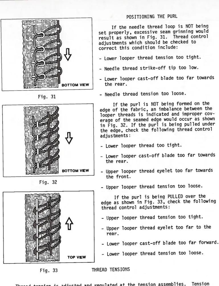
POSITIONING THE PURL
If the needle thread loop is NOT being set properly, excessive seam grinning would result as shown in Fig. 31. Thread control adjustments which should be checked to correct this condition include:
- Lower looper thread tension too tight.
- Needle thread strike-off tip too low.
- Lower looper cast-off blade too far towards the rear.
- Needle thread tension too loose.
If the purl is NOT being formed on the edge of the fabric, an imbalance between the
looper threads is indicated and improper cov erage of the seamed edge would occur as shown in Fig. 32. If the purl is being pulled under the edge, check the following thread control adjustments:
- Lower looper thread too tight.
- Lower looper cast-off blade too far towards the rear.
- Upper looper thread eyelet too far towards the front.
- Upper looper thread tension too loose.
If the purl is being PULLED over the edge as shown in Fig. 33, check the following thread control adjustments:
- Upper looper thread tension too tight.
- Upper looper thread eyelet too far to the rear.
- Lower looper cast-off blade too far forward.
- Lower looper thread tension too loose.
Fig. 33 THREAD TENSIONS
Thread tension is adjusted and regulated at the tension assemblies. Tension on the threads should be only enough to secure proper stitch formation. Using a postal scale, the measurements are taken with the needles at the top of their stroke.
The following tensions are starting points only and may have to be changed due to type and size of thread or material being sewn.
BOTTOM VIEW
Fig. 31
BOTTOM VIEW
Fig. 32
*
TOP VIEW
THREAD TENSION (Continued)
- 401 needle thread tension is 2 to 2 1/2 oz (57 to 71 gr), to be measured straight out of lower eyelet located on left side of needle head.
- Overedge needle thread tension is 1 1/2 to 2 oz (43 to 57 gr), to be measured straight out of lower eyelet located on right side of needle head.
- Overedge lower looper thread tension is 1 to 1 1/2 oz (28 to 43 gr), to be measured straight out of thread tube located to rear of throat plate.
- Overedge upper looper thread tension is 1 to 1 1/2 oz (28 to 43 gr), to be measured straight out the bottom of thread tube located to right of upper knife driving arm.
- 401 lower looper thread tension is 1 to 1 1/2 oz (28 to 43 qr), to be measured straight out of eye at point of looper.
INTERNAL FEED ADJUSTMENTS
The basic drive motion for horizontal travel of the main and differential feeds is derived from stitch regulator assembly (A, Fig. 34). This motion is transmitted to the individual feed bars by means of the main feed segment (B) and differential feed segment (C). Both segments are affixed to a common shaft which is driven in a rocking motion by an adjustable eccentric within the stitch regulator assembly. As a result, any stitch length change will effect the travel of both the main and diff—
erential feeds.
The location of the feed drive links (D and E) within each segment will effect the
___________________
_____
feed travel individually. The longest feed
travel is obtained with the link located at c H
the highest position within the segment.This E G
position of the link is fixed for the main
/
feed and adjusted by a thumbscrew for the
B D
differential feed. u T
The adjustable eccentric within stitch L
regulator assembly (A) is set at the factory N A
to produce a maximum stitch length of V
7 S.P.I. for the main feed and 5 S.P.I. for
the differential feed. K S
Longer feed travel for both feeds can be
obtained by loosening inner lock screw (F) Fig. 34 and turning limit screw (G) counterclockwise.
Tighten screw (F). Rotate handwheel in operating direction and check feed travel in throat plate slots making sure the feeds do not contact the front or rear ends of the slots.
If necessary, repeat procedure until desired or maximum stitch length is pro duced, then torque limit screw (G) to 20 in. lbs. (23 cm/kg). An access screw, located at the left front of casting below the upper looper thread tube is provided for this adjustment.
Both main and differential feeds can be centered front to back in the throat plate by following instructions listed in sequence for adjusting feed drive segments(B and C).
DIFFERENTIAL FEED DRIVE SEGMENT
- Set push button stitch regulator (A, Fig. 34) to maximum stitch length by depress ing and holding plunger (H) down in notch of stitch regulator eccentric and turning handwheel in operating direction.
- Turn differential thumbscrew (J) counterclockwise until differential feed indicator pointer (K) is positioned at the bottom of graduated scale on indicator plate (L).
- Turn stop screw (M) counterclockwise as required to allow full up and down movement of pointer (K).
- Drain oil and remove bottom cover.
- Rotate handwheel in operating direction until the differential feed dog is positioned all the way to the rear.
- Loosen clamp screw (N) and position differential feed drive segment (C) forward.
Temporarily tighten screw (N) to hold segment in position, yet allowing segment to be repositioned on feed drive rock shaft (P) for adjustment.
- Manually operate pointer (K) up and down so sliding block (R) travels to the top and bottom of segment slot. At this time, while operating pointer, observe diff erential feed movement. Then gradually tap the top - front section of segment (C) to the rear as required until differential feed shows no movement when pointer is operated and sliding block travels the full length of segment slot. Recheck set ting, then torque clamp screw (N) to 38 - 40 in. lbs. (44 - 46 cm/kg).
- Replace bottom cover and torque its mounting screws to 19 - 21 in. lbs. (22 - 24 cm/kg), then fill machine with oil to proper level.
MAIN FEED DRIVE SEGMENT:
- Set push button stitch regulator (A) to maximum stitch length by depressing and holding plunger (H) down in notch of stitch regulator eccentric and turning hand- wheel in operating direction.
- Drain oil and remove bottom cover.
- Rotate handwheel in operating direction until needle head is at highest position.
- Loosen clamp screw CS) and clamping nut CT).
- Position main feed drive segment (B) on feed drive rock shaft (P) so when main feed drive link CD) travels the full length of the segment slot, the middle row of main feed dog teeth are centered in the slot of throat plate and feed shows no movement. Recheck setting, then torque clamp screw
Cs)
to 38 - 40 in. lbs.(44 - 46 cm/kg).
- Set main feed drive link CD) at the top of the segment slot and torque clamping nut CT) to 19 - 21 in. lbs. (22 - 24 cm/kg).
- Replace bottom cover and torque its mounting screws to 19 - 21 in. lbs.
(22 - 24 cm/kg), then fill machine with oil to proper level.
- If necessary, further adjustment can be made to the main and differential feeds by loosening locknuts (U), then rotating eccentric ferrules CV) as required to
Hold ferrules in position and tighten locknuts.
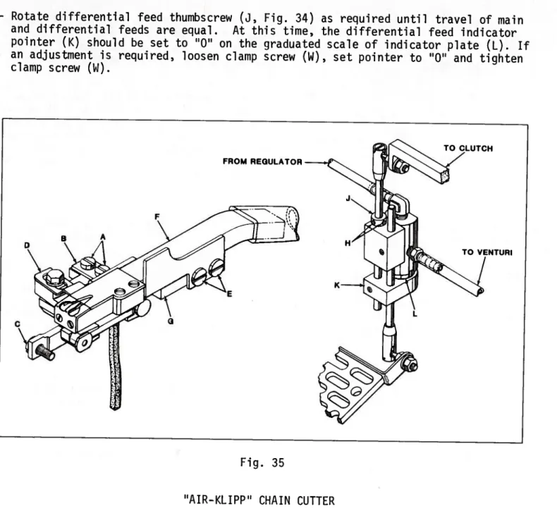
DIFFERENTIAL FEED INDICATOR POINTER
- Rotate differential feed thumbscrew (3, Fig. 34) as required until travel of main and differential feeds are equal. At this time, the differential feed indicator pointer (K) should be set to ‘O on the graduated scale of indicator plate (L). If an adjustment is required, loosen clamp screw (W), set pointer to “0” and tighten clamp screw (i).
“AIR-KLIPP” CHAIN CUTTER
1. If adjustment to the ‘AIR-KLIPP” chain cutter is necessary; remove cloth plate, cast-off support plate, throat plate, 401 looper take-up, take-up spacer, rear throat plate support and rear throat plate support bracket.
2. Remove “AIR-KLIPP” chain cutter assembly from the machine by removing screws (A, Fig. 35), washer plate (B) and screw (C).
With “AIR-KLIPP” chain cutter assembly out of machine; position movable knife CD) to its extreme right. Loosen screws (E) and press air tube (F) and base (G) together applying only enough pressure on movable knife to ensure proper cutting maintaining a slight shear angle, then tighten screws (E).
FROM REGULATOR
A
C
TO VENTURI
Fig. 35
“AIR-KLIPP” CHAIN CUTTER (Continued) When the movable knife (A, Fig. 36) travels from extreme left to the right; its cutting edge must be even with the cutting edge of stationary knife - Ref. point B.
To adjust movable knife (A), loosen screw (C) and position knife front to back as re quired. Hold knife in position and tighten screw (C). Check, if movable knife (A) is adjusted properly it will cut a single strand of thread when manually moving knife left to right.
3. Re-assemble “AIR-KLIPP’ chain cutter assembly,the main feed and plate (B, Fig. 35) to the machine with screws (A and C).
With “AIR-KLIPP” chain cutter assembly in position, temporarily replace throat plate and check for a 1/64 inch (.4mm) clearance between front edge of air tube (D, Fig. 36) and rear edge of throat plate (E), as shown. If a clearance adjust ment is necessary, loosen screws (E, Fig. 35) and adjust the air tube (F) front to
back on “AIR—KLIPP” chain cutter base as required. Re-adjust movable knife press ure as outlined in STEP 2, then tighten screws (E).
Before tightening mounting screws be sure the right side of “AIR-KLIPP” chain cut ter base is set flush against the main feed bar. Tighten screws (A and C).
NOTE: Main stitch length determines movable knife travel and must be set before mak ing the following adjustment.
With main stitch length set and movable knife (A, Fig. 36) positioned to its ex treme right; loosen screw (C) and adjust movable knife left to right as required to extend no less than 1/64 inch. (.4mm) beyond the cutting edge of stationary knife as shown in Fig. 36. Clearance must be maintained between the moving knife and the inner wall of air tube - Ref. Point F. Hold knife in position and tighten screw (C).
4. To adjust the air valve system, loosen screws (H, Fig. 35) and set collar (J) to permit acuator block (K) to just contact button of air valve - Ref. point L, when button is fully extended, then tighten screws (H). When treadle is pressed to start sewing, the air valve must open before the clutch is engaged.
1I64 (.4mm)
1164 (.4mm)
Fig. 36
“AIR-KLIPP” CHAIN CUTTER (Continued) 5. Replace parts removed in STEP 1 in a re
verse manner. Turn handwheel in operating direction until the needles are at high est position.
To set 401 looper thread cam take-up (A, Fig. 37), loosen nut (B) and position cam take-up so its longest flat is para llel with cast-off plate (C). Torque nut (B) to 24 - 25 in/lbs. (28—29 cm/kg).
To center cam take-up (A) in slot of
cast-off plate (C) loosen screws (D) and Fig. 37 adjust cast-off plate left to right as
required, then tighten screws. Rotate handwheel in operating direction several times to check for binding.
CRANKSHAFT REMOVAL
PRIOR TO CRANKSHAFT REMOVAL: DRAIN OIL AND REMOVE THROAT PLATE AND BOTH TOP AND BOTTOM COVERS.
1. Remove nut (A, Fig. 38), washer (B), 401 looper thread take-up (C) and take-up spacer (D). Loosen screws E, F, G and H securing stitch regulator assembly (J) to crankshaft.
NOTE: Tension spring (K) may drop out of stitch regulator assembly (J) during crank shaft removal.
NOTE: To re-assemble stitch regulator assembly (J), SEE STEP NO. 12.
2. Remove four screws (L) and counterweights (M).
IMPORTANT: Mark counterweights and crankshaft cheeks for correct positioning of counterweights during re-assembly.
3. Remove oil tube (N) and all connecting rod bearing caps at points P, R, S and T on crankshaft.
IMPORTANT: During re-assembly, be sure trademarks stamped on both the connecting rods and bearing caps are positioned on the same side and face towards the left end of machine.
4. Remove inner crankshaft bearing stud (U), to allow inner crankshaft bearing (V) to slide out with crankshaft.
5. Loosen clamp nut (A, Fig. 39). Slide upper knife driving arm (B) to the left until driving lever (C) drops off arm (B) allowing bearing cap (D) to be positioned for removal. Remove two screws (E) and bearing cap (D) - Ref. point (W, Fig. 38) on crankshaft.
6. Remove screw (X) and take off pulley cap (Y).
7. Loosen two screws
(z)
and slide belt pulley (AA) off crankshaft.8. Remove three screws (AB), bearing plate (AC), spacer collars AD and AE.
Y
Fig. 38
9. Remove needle driving lever connecting rod and withdraw crankshaft from machine.
With crankshaft out of machine, check ball bearing (AF) for wear. To remove bearing (AF) use an arbor press. Only after bearing (AF) is pressed off crank shaft can flange (AG), thrust washer (AH) and bearing CV) be removed from crank shaft.
NOTE: When pressing a new bearing onto crankshaft, be sure it seats against thrust washer (AH).
x
AC
AE AF
PRIOR TO RE-ASSEMBLING CRANKSHAFT, THOROUGHLY CLEAN MACHINE.
10. To re-assemble crankshaft, follow steps outlined for removal in a reverse manner.
During re-assembly, check exploded views for proper positions of parts on crank shaft. Rotate pulley cap (Y) periodical ly during re-assembly to be sure no bind ing occurs.
11. In order to re-assemble stitch regulator assembly (J) correctly on crankshaft, tool No. 21270 OP is required. Slide tool (A, Fig. 40) through stitch regula tor assembly and rotate tool until its slot slips into tension spring (B) posi tioned in stitch regulator mechanism.
Thread tool onto crankshaft and slide crankshaft through stitch regulator,then unscrew and remove tool. With stitch re gulator assembly positioned on crank shaft, turn handwheel in operating di rection until first screw hole of stitch regulator assembly (J) aligns with tim ing groove on crankshaft for spot screw CE, Fig. 38), then insert and tighten spot screw (E); continue to rotate hand- wheel until hole for screw (F) is visi
ble, then insert and tighten set screw (F). To secure inner lock screw (G) and limiting screw (H) - SEE INTERNAL FEED ADJUSTMENT.
Fig. 39
Fig. 40
-a-.m... —
_____________________
MAIN FRAME, MISCELLANEOUS COV[RS, PLATES ANI) BUSUI NGS
Aint.
P1J±LPfl Reib
Screw, for top cover 2
Top Cover 1
Screw, for upper oil shield cover 12
Upper Oil Shield Cover 1
Gasket, for upper oil shield cover 1
Metol 1 ic Filter 1
Screw, for oil collector 1
Oil Collector 1
Oil Wick As Req.
Plug Screw 1
Needle Lever Drive Shaft Bushing 4
Oil Filler Screw Assembly 1
Screw, for oil system 2
Stitch Length Regulator 1
Stitch Length Regulator Return Spring 1
Screw, for sti tch length regulator 1
Nut 1
Screw, for cloth plate stud 1
Cloth Plate Stud 1
Foot Lifter Shaft Bushing 2
Upper Knife On vi ng Arm Bushing, left 1
Upper Knife Driving Arm Bushing, right 1
Lower Looper Bar Bushing 1
Oil Tube 1
Differential Feed Rocker Shaft Bushing 1
Plug Screw, for bed 1
Differential Feed Rock Shaft Bushing 2
Cloth Plate Fabric Guard, for machines without “AIR—KLIPP” chain cut
ter 1
Screw, for cloth plate 1
Cloth Plate, for machines without “AIR-KLTPP” chain cutter 1 Cloth Plate, for machines with “AIR—KLIPP” chain cutter 1
Bottom Cover 1
Oil Tube, tygothane 1
Oil Tube, brass 1
Retaining Ring, for oil tube 1
Porex Filter, for oil tube 1
Spring, for oil tube 1
Oil Tube, tygothane 1
Oil Pump Tube 1
Isolator 4
Bottom Cover Plate 1
Bottom Cover Plate Gasket 1
Porex Filter Sleeve 1
Pin 1
Oil Filter 1
Oil Pump Tube 1
Oil Tube Spacer 1
Screw, for bottom cover 1
Screw, for bottom cover 17
Bottom Cover Gasket 1
Oil Gauge Float 1
Screw, for bottom cover 1
Screw, for oil tube spring 1
Oil Gauge Indicator 1
Spring, for oil tube 1
Felt Pad 1
Screw, for cloth plate latch spring 2
Cloth Plate Latch Spring 1
Screw, for cloth plate fabric guard 2
Screw, for feed bar thrust washer 2
Differential Feed Bar Thrust Washer 1
Crankshaft Bearing, inner left 1
Plug Screw 1
401 Looper Drive Shaft Bushing, left 1
Base Plate Extension 1
oi Looper Drive Shaft Bushing, right 1
Screw, for base plate extension 2
Ref. Port
No. No.
22894 AG
2 39002 R
3 22541 B
4 39002 P
5 39082 F
6 39894 C
7 22569 D
O 39094 0
O CL21
18 22565
11 39852 M
12 39893 C
13 88
14 39849 C
15 39849 F
16 22804 AK
17 15037 A
18 22560
10 30501 K
20 30855 D
21 30573 K
22 30573 AA
23 30544 X
24 643-400 Blk
25 39536 BY
26 22894 Y
27 39836 Y
28 39578 F
29 22657 D—12
30 39501 DX
31 39501 DY
32 39782 A
33 30593 K
34 666-271
35 660—506
36 56393 8
37 56393 V
38 666-280
39 39593 LI
40 39595
41 39782
42 39782 B
43 39893 8
44 P1-18
45 39893 F
46 660-645
47 39893 D
48 22806 A
49 22541 B
50 39882 5
51 39593 C
52 22586 T
53 22569 D
54 39593 D
55 39893 E
56 666—268
57 90
58 39B32
59 138
60 22569 8
61 39834 0
62 39890 F
63 22539 K
64 39844 E
65 39582 F
66 39644 C
67 22653 0—4
CRANKSHAFT MECHANISM
Amt.
Req.
1 39690 A 2 39890 C
3 660-443
4 39590 J 5 39590 G
6 660-268
7 39590 R 8 39590 5 9 39590 H 10 22569 B 1]. 39521 GA
12 95
13 39821 A 14 22769 B 15 29477 MK 16 39852 A
17 77
18 22587 M 19 39516-625
- 39516-626
- 39516-627 20 30-106 Blk.
21 51—569 Blk.
22 C067 E
23 40-46
24 258
25 39890 E
26 97A
27 39691 28 39593 J 29 39591 K 30 22747 B
Stud, for crankshaft bearing 1
Crankshaft Bearing, inner right 1
“0” Ring, for crankshaft bearing, inner right 1
Thrust Washer 1
Crankshaft Ball Bearing Housing 1
Crankshaft Ball Bearing 1
Ball Bearing Stop Collar 1
Spacer Collar 1
Crankshaft Ball Bearing Retaining Plate 1 Screw, for ball bearing retaining plate and housing 3
Pulley 1
Screw, for pulley 2
Pulley Cap 1
Screw, for pulley cap 1
Crankshaft and Needle Driving Connecting Rod Assembly 1 Needle Driving Connecting Rod Assembly 1
Screw 1
Screw 2
Needle Bearing, .0625 inch (1.588 mm) diameter 28 Needle Bearing, .0626 inch (1.590 mm) diameter 28 Needle Bearing, .0627 inch (1.593 mm) diameter 28
Wood Plug, birch 1
Vent Plug 1
Cork Plug 1
Washer 1
Nut 1
Split Bearing and Oil Pump 1
Screw, for split bearing and oil pump 2
Crankshaft Counterweight, right 1
Oil Pump Tube 1
Crankshaft Counterweight, left 1
Screw, for crankshaft counterweight 4
Ref. Part
No. No. Description
£8
IL
FEED DRIVE MECHANISM
Ref. Part Amt.
No. No. Description Req.
1 93 A Screw, for main feed dog 1
2 Main Feed Dog (See page 49) 1
3 93 Screw, for differential feed dog 1
4 Differential Feed Dog (See page 49) 1
5 39536 BE Stud, for differential feed bar 1
6 39838 Feed Lift Block 1
7 39823 Take-up Spacer 1
8 258 Nut 1
9 39868 R 401 Looper Thread Take-up 1
10 39536 E Nut, for main feed bar driving stud 1
11 39536 BU Main Feed Driving Eccentric Ferrule 1
12 39836 W Main Feed Bar Driving Connection 1
13 39536 BE Stud, for main feed bar 1
14 22569 G Screw, for feed bar thrust washer 2
15 39834 D Differential Feed Bar Thrust Washer 1
16 22894 3 Screw, for feed bar guide 1
17 39535 N Feed Bar Guide, right 1
18 39834 E Differential Feed Bar 1
19 39535 3 Feed Bar Guide Block 1
20 39834 F Main Feed Bar 1
21 39536 BX Main Feed Bar Thrust Washer 1
22 39835 F Feed Leveling Pin 1
23 22894 3 Screw, for feed leveling pin 1
24 660-466 “E” Ring, for feed control shaft 1
25 40-144 Washer, for feed control shaft 1
26 39836 AC Feed Control Shaft 1
27 39836 R Stitch Indicator Pointer 1
28 93 Screw 1
29 39836 AB Stitch Indicator Plate 1
30 22565 C Set Screw 1
31 92201 Pressure Plug Screw 1
32 39536 CA Pressure Plug 1
33 39836 N Stitch Regulating Screw 1
34 660—219 E Pin 1
35 39836 AD Main Feed Return Spring 1
36 61248 G Collar, for feed control shaft 1
37 89 Screw 2
38 39536 BU Differential Feed Drive Stud Ferrule 1
39 39536 E Nut, for differential feed bar stud 1
40 39849 A Stitch Regulator Assembly 1
41 22894 0 Spot Screw 1
42 22894 C Set Screw 1
43 22585 T Stop Screw 1
44 22894 AJ Locking Screw 1
45 22571 H Socket Set Screw 2
46 22651 EM-4 Set Screw 2
47 39849 D Tension Spring 1
48 660-642 Needle Bearing 1
49 thru 85 See following page
FEED DRIVE MECHANISM
Ref. Part Amt.
No. No. Description Req.
1 thru 48 See preceding page
49 39836 U Differential Feed Drive Connecting Rod 1
50 77 Screw 1
51 660-647 Unit Cage Bearing 1
52 35751 G Collar, for feed drive rock shaft 1
53 22572 B Screw 1
54 62244 A Thrust Washer, for feed drive rock shaft 1
55 51236 A Link Pin, for differential feed drive lever 1
56 39836 X Differential Feed Drive Lever 1
57 40-139 Washer 1
58 22852 A Screw 1
59 39536 BB Differential Feed Drive Link Pin 1
60 39536 BA Differential Feed Control Link 1
61 22760 E Screw, for differential feed control link 1
62 39536 AX Differential Feed Drive Link 1
63 39536 AT Differential Feed Control Lever 1
64 22652 A-6 Screw 1
65 41071 G Nut, for differential feed control link screw 1
66 39536 CJ Screw, for main feed return spring 1
67 39836 M Differential Conrol Lever Actuator 1
68 22652 A-8 Screw 1
69 89-64 Plug 1
70 22517 Screw, for stitch indicator plate 1
71 22789 C Stop Screw 1
72 39836 V Main Feed Drive Segment 1
73 80557 Washer 1
74 22852 A Screw 1
75 39836 AE Differential Feed Drive Segment 1
76 22852 A Screw 1
77 80557 Washer 1
78 39536 AY-247 Differential Feed Segment Sliding Block, marked “K”,
.247 inch (6.274 mm) wide 1
- 39536 AY-248 Differential Feed Segment Sliding Block, marked “L”,
.248 inch (6.299 tin) wide 1
- 39536 AY-249 Differential Feed Segment Sliding Block, marked “M”,
.249 inch (6.325 mm) wide 1
79 22733 Set Screw 1
80 39836 Z Main Feed Drive Connecting Rod Stud 1
81 8372 A Washer, for main feed drive connecting rod stud 1 82 12934 A Nut, for main feed drive connecting rod stud 1
83 39836 K Feed Drive Rock Shaft 1
84 660-467 “E” Ring, for feed drive rock shaft 1
85 62244 A Thrust Washer, for feed drive rock shaft 1
NEEDLE DRIVE MECHANISM AND TAKE-UPS Ref.
No.
Part
No. Description Ant.
Req.
1 1 1 1 1 1 Req.
2 1 1 1 1 1 2 1 1 1 1 1 Req.
1 1 1 1 1 1 1 1 1 39852 R Needle Guide Bar
2 C067 E Cork
3 CL21 Oil Wick
4 22894 C Set Screw
5 22894 L Spot Screw
6 39852 C Needle Lever Roller Pin
7 WO-3 Wool Yarn As
8 660-667 ‘0” Ring, for needle guide bar
9 660-416 Retaining Ring, for needle lever roller pin
10 39852
Q
Needle Lever11 22852 C Screw
12 40-139 Washer
13 39863 T Upper and Lower Looper Thread Take-Up 14 39852 E Needle Lever Drive Shaft
15 39573 A Thrust Washer
16 660-442 Retaining Ring, for needle lever drive shaft 17 39852 D Needle Drive Lever
18 22852 C Screw
19 40-139 Washer
20 51236 A Link Pin, for needle drive lever
21 WO-3 Wool Yarn As
22 39843 D Needle Lever Drive Shaft Thrust Clamp Collar
23 22652 B-10 Screw
24 22588 A Screw, for needle thread cam pull-off 25 39863 D 503 Needle Thread Cam Pull-off
26 39863 J 401 Needle Thread Cam Pull-off
27 39863 S Upper and Looper Looper Thread Take-up Lever
28 22572 B Screw
29 22588 A Screw, for thread take-up
30 39852 S-5 Needle Head, marked “BS”, for No. 5 1/8 gauge,
all Styles 1
- 39852 S-8 Needle Head, marked “BT”, for Nos. 8 1/8 and 8 3/16
gauge, all Styles 1
- 39852 S-12 Needle Head, marked “BU”, for No. 12-3/16 gauge,
all Styles 1
31 22784 L Screw, for top needle head eyelet I
32 39852 N Needle Head Eyelet, top 1
33 28 C Screw, for needle 2
34 39852 K-5 Needle Head Eyelet, for No. 39852 S-5 1
- 39852 K-8 Needle Head Eyelet, for No. 39852 S-8 1
- 39852 K-12 Needle Head Eyelet, for No. 39852 S—12 1 35 22738 B Screw, for No. 39852 S-5 or No. 39852 S-8 1
- 605 Screw, for No. 39852 S-12 1
36 120 GS Needle, for all Styles except 398—27, 398-28 2
— 120 GAS Needle, for Styles 398-27, 398-28 2
37 39594 N Oil Splasher 1
38 87 U Screw, for oil splasher 1
v9I,
•I,I II,
1
I’)II(
DL
LOWER LOOPER DRIVING MECHANISM AND FOOT LIFTER PARTS
Ref. Part Amt.
No. No. Description
1 39808 D Lower Looper, marked “ACZ” 1
2 39151 Nut, for lower looper bar 1
3 52344 Lower Looper Bar 1
4 77 Screw, for connecting link pin 1
5 660-206 “0” Ring, for lower looper bar driving lever shaft 1 6 22894 AE Screw, for lower looper bar driving lever shaft 2
7 482 C Lower Looper Shaft Collar 1
8 22894 C Screw 2
9 39894 C Oil Pump Oiler 1
10 12982 Nut, for oil pump oiler screw 1
11 22894 J Screw, for oil pump oiler 1
12 538 Screw, for ball joint guide fork 2
13 39644 X Ball Joint Guide Fork 1
14 39644 R—2 Shim, for ball joint guide fork, .002 inch (.051 niii) thick-- As Req.
- 39644 R—5 Shim, for ball joint guide fork, .005 inch (.127 mm) thick—— As Req.
15 666-255 Felt Plug, for lower looper drive lever connecting rod 1
16 39644 F Lower Looper Drive Lever Connecting Rod 1
17 22729 D Screw 2
18 22729 E Screw 2
19 77 Screw, for connecting link pin 1
20 39844 Lower Looper Bar Driving Lever 1
21 39844 B Lower Looper Bar Driving Lever Shaft 1
22 39544 D Lower Looper Bar Connecting Link Pin 2
23 39544 B Lower Looper Bar Connecting Link 1
24 Presser Foot (See pages 49, 50, 51) 1
25 22571 D Plug Screw, for foot lifter hole 1
26 22566 B Screw, for foot lifter lever 1
27 39855 Foot Lifter Lever 1
28 39855 B Foot Lifter Intermediate Lever 1
29 41332 J Washer 1
30 39555 C Foot Lifter Lever Arm 1
31 627 Screw 1
32 12538 Locknut 2
33 22597 E Screw 2
34 8372 A Washer, for connecting link 1
35 39855 A Foot Lifter Lever Spring 1
36 660-142 Cotter Pin, for connecting link 2
37 39857 H Foot Lifter Lever Connecting Link 1
38 12865 Thrust Collar, for foot lifter lever shaft 1
39 88 Screw 2
40 39855 C Foot Lifter Lever Shaft 1
41 258 A Nut, for presser arm screw 1
42 22791 H Screw, for presser arm 1
43 39656 B Presser Arm, on Styles 398-21, 398-29 1
- 39856 D Presser Arm, on all Styles except 398-21, 398-29 1
44 39856 C Chain Cutting Knife 1
45 22547 A Screw, for chain cutting knife 1
46 21695 AN Finger Guard, on all Styles except 398-24, 398—25 1
46A 21695 AL Finger Guard, on Styles 398-24, 398-25 1
47 53678 N Washer 1
48 22797 A Screw, for chain cutting knife and finger guard 1 49 39830 AJ Shoulder Screw, for presser foot bottom spring 1 50 39830 AL Spring, for presser foot bottom, on all Styles except 398-24,
398-25, 398—28 1