When recharging the refrigerant in the refrigeration cycle, do not mix any other refrigerant or air except R410A into the specified refrigerant. Refrigerant cannot be obtained from the outdoor unit; otherwise, a serious accident such as breakage or injury will occur. If you use gas for charging, the composition of the refrigerant and then the characteristics of the air conditioner will change.).
SPECIFICATIONS
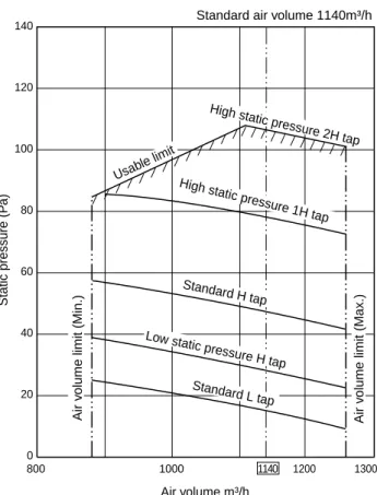
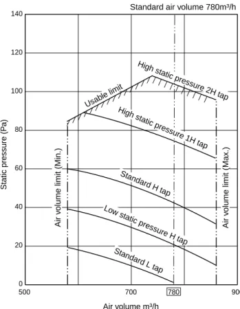
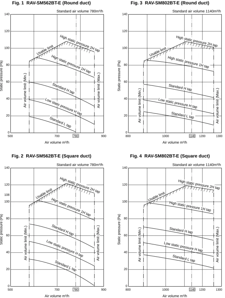
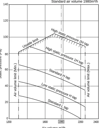
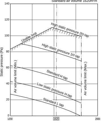
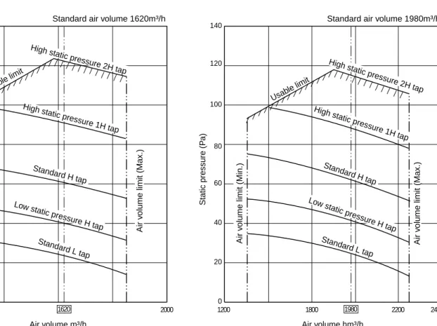
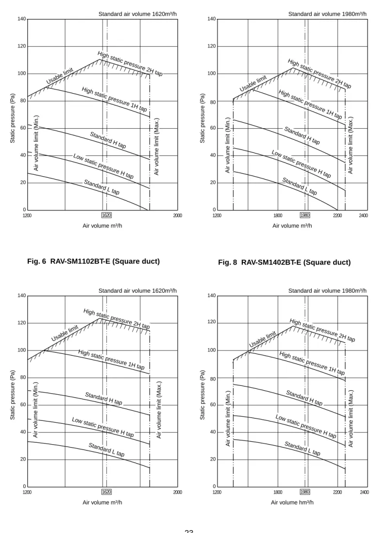
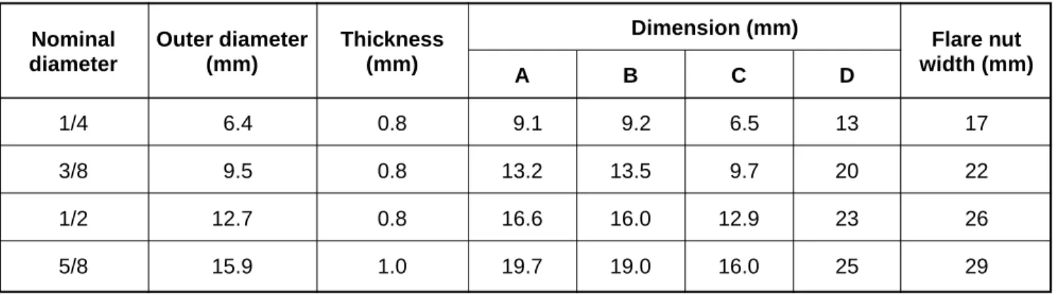
AIR DUCTING WORK
CONSTRUCTION VIEWS (EXTERNAL VIEWS)
For equipment maintenance, install a control port A in the position shown below. Using the separately available drain kit, a drain of 300 (mm) from the drain hole of the main unit is necessary.
SYSTEMATIC REFRIGERATING CYCLE DIAGRAM
The compressor frequency (Hz) measured with a clamp meter is 2 times the revolutions (rps) of the compressor. The cooling cycle of the indoor units varies according to the models to be combined. For the cooling cycles of the other indoor units, refer to the corresponding Service Manuals described in the list on the cover.
WIRING DIAGRAM
SPECIFICATIONS OF ELECTRICAL PARTS
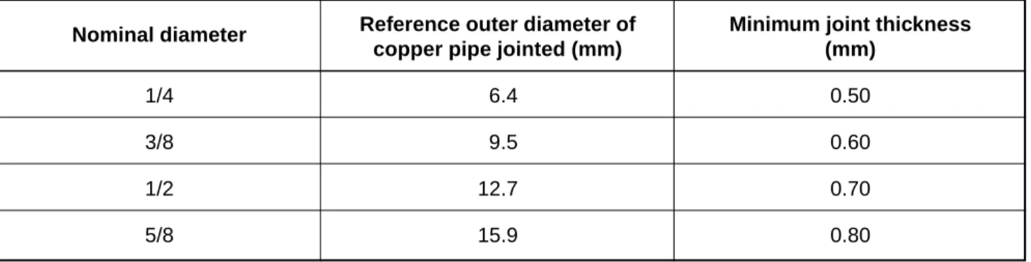
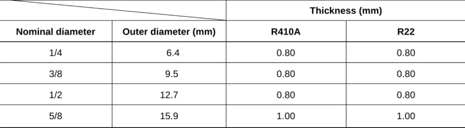
REFRIGERANT R410A
There is a possibility that a large amount of bad oil or moisture remains inside the pipe. Turn the existing pipe switch on the cycle control PC board on the outdoor unit to the ON side. By pressing the refrigerant recovery switch on the terminal block of the outdoor unit, forced cooling starts.
CONTROL BLOCK DIAGRAM
Based on EEPROM data, the speed of the indoor fan or the setting of whether to adjust the air direction or not is selected. When the cooling operation is started, the air velocity selects a downward slope, i.e. the high position. If the temperature is just at the differential limit, the air speed does not change.
When the heating function is started, the air speed selects an upward slope, i.e. the high position. In auto cooling/heating, the revolving frequency of [HH] is set higher than in standard cooling/heating. However, the rotational frequency is limited in automatic heating mode, as shown in the following figure.
When operation starts or when Tc or Tcj becomes lower than 30 °C after operation, the temperature is controlled between the values in brackets A and B. The display TEST] in the display part disappears and the state returns to normal shutdown. condition.). lt;In the case of a wireless remote control>. The operation content can be selected from the remote controller and the central controller on the indoor unit side, and the operation is performed with the content selected last.
In the initial operation after power-on, the position is automatically controlled according to the working status (COOL/HEAT).
CIRCUIT CONFIGURATION AND CONTROL SPECIFICATIONS
In heating operation, PMV is controlled with the temperature difference between TS sensor and TE sensor. A sensor problem can cause fluid backflow or abnormal overheating, resulting in excessive shortening of compressor life. V The outdoor fan is controlled by TE, TD and TO sensors and also revolution frequency of the operation.
R Only for 60 seconds after the operation starts, the fan is fixed with the maximum fan tap corresponding to the zone in the following table. S In the event that the TE sensor has come out of its holder, the fan is controlled so that the fan revolution frequency increases regardless of TE if the temperature of the TD sensor has risen. T When the above status R occurs frequently, it is assumed that the filter of the suction section of the indoor unit is dirty.
Just like a test run, it is recommended to turn on the compressor in advance when starting operation after the power to the compressor has been cut off for a long time. No Power ON Continuous ON (L) Continuous ON (M) Power ON condition. In problems with TE sensor). QI heating operation, defrosting operation is performed when the TE sensor temperature meets any condition in A zone to D zone.
The defrost operation also ends when the defrost function has continued for 10 minutes even if the temperature of the TE sensor has become 7°C or lower.
TROUBLESHOOTING
Error → Lamp display confirmation →. When the 4-way air discharge cassette type wireless remote controller is connected). Terminal Resistance Check (Connection Interface SW01) Check the check code of the corresponding device using the remote controller Wireless sensor. lamp display Operating hours ready. Remote control power failure, defective indoor EEPROM 1. Check cables between the remote control. including socket insertion): The phenomenon of automatic address repetition occurred.
The control codes are classified into Type A and Type B according to the remote control used. Are connections between connections. board and connectors CN51 of indoor P.C. Check connections of A, B terminal blocks. E03 error] is detected when the indoor unit cannot receive a signal sent from the main remote controller (and central controller).
Since communication is disabled, [E03] is not displayed on the main remote controller and the central control unit. There is no display of the control code or alarm history for the main remote control.
REPLACEMENT OF SERVICE INDOOR P.C. BOARD
Press the SET, CL and TEST buttons of the remote control at the same time for 4 seconds or more. The fan of the selected indoor unit runs and the louver starts to swing if there is one. Using the temperature / set buttons, the article code (DN) can be moved up and down one by one. Setting the filter sign lighting time) Mark the set data displayed at this time.
Depending on the system configuration, turn on the power of the indoor unit using one of the methods below. Turn on the power of the indoor unit whose P.C. board has been replaced by the service P.C. board with a method in the following items. The line address/indoor address of the replaced indoor unit is automatically set to the free addresses except addresses of other indoor units that have not been replaced.
It is recommended to note that the refrigerant piping containing the corresponding indoor unit and the corresponding indoor unit is master or sub in the group control. r3 Write the setup contents to EEPROM. The fan of the selected indoor unit runs and the louver starts swinging, if present. The content of the setting data displayed during this time should be agreed with the content in the previous memorandum in r1.
Same as above, check the setting data content and then change it to the data content in the previous memorandum.
SETUP AT LOCAL SITE AND OTHERS
1 Remove a screw that secures the serial plate of the receiver part on the wireless remote control. 2 Perform a test operation with button on the wireless remote controller. and LED flash during test operation. Under status of [TEST RUN ON], the temperature adjustment from the wireless remote controller is invalid.
3 Press the button on the wireless remote controller and select an operation mode [COOL] or [HEAT] with the MODE button. All the display lights of the sensor part of the wireless controller flash during the tst operation.). After test operation, press the [Start/Stop] button to stop operation. lt;Overview of wireless remote controller test operation>.
Use the timer on the main or sub remote control. lt;Wireless remote control>. The indoor unit connected to the outdoor unit (Individual/Master of twin) controls the room temperature according to the setting on the remote control. The setting range (operation mode/air volume selection/setting temperature) of the indoor unit that has been set on the main unit is reflected on the remote controller.
The central control address number is displayed as the line number of the central control remote control.
ADDRESS SETUP
Master unit (= 1): The representative of multiple indoor units in group operation sends/receives signals to/from the remote controllers and sub indoor units. It has no relation to an indoor unit communicating serially with the outdoor units.). For the example above, perform setting by connecting the wired remote controller alone without remote controller inter-unit cable.
In the event that the addresses of the indoor units will be determined before the work on the pipelines after the work with the cables (manual setting from the remote control). lt;Address Setting Procedure>. Knowing the addresses of the indoor unit, although the position of the indoor unit case is recognized. When other indoor units are connected to the same remote controller (group control unit), each time the UNIT button is pressed, the numbers of the other units will also be displayed.
To confirm unit no. Follow the procedure during operation) (in this procedure, the indoor units stop in group control.). The indoor unit numbers in the group control are displayed successively, and the fan, slats and drain pump of the corresponding indoor unit are turned on. 2 Each time the UNIT button is pressed, the unit numbers in the group control are displayed successively.
DETACHMENTS
When attaching the turbo fan, make sure the fan head matches the D-cut of the motor shaft. When reconnecting the lead wires to the compressor terminals after replacing the compressor, be sure to seal the Faston terminal without loosening it. When reconnecting the lead wires to the compressor terminals after replacing the compressor, be sure to seal the Faston terminal without loosening it.
EXPLODED VIEWS AND PARTS LIST
CORD HEATER INSTALLATION WORK
Separate the cord heater power supply from the air conditioner power supply and connect it to the exclusive breaker. Be sure to connect the fuse and thermostat to the LIVE side of the cord heater. Drill a hole in the base plate of the outdoor unit and fix the cord heater to the base plate of the outdoor unit using a P-shaped clamp.
These holes are used to fix the cord heater to the base plate of the outdoor unit with a P-shaped clamp. This conduit is designed to protect the cord heater from the mounting screws used to secure the anchor feet. As shown in the left figure, install the cord heater (1.5 m) on the base plate of the outdoor unit using a P-shaped clamp and screws (self-tapping screw type B Ø4 × 6 mm, stainless).
Carry out the cord heater cable process together with the connection cable of the fan motor and collect the remaining part of the cables at the cable process section of the inverter. Attach the power cord for the cord heater to the terminal block mounting plate using the P-shaped clip and pull it out of the wiring area of the side box (R). Check if the marked part of the cord heater is on the base plate of the outdoor unit or close to it.
When installing, connect the power cord for the cord heater to another circuit breaker that is separate from a circuit breaker for the air conditioner power cord.