In this context, magnetic cooling is one of the most promising for near-room temperature applications.
Motivation and objectives
Experimentally characterize the thermodynamic performance of a commercial wine cooler powered by a vapor compression refrigeration system; Build the designed prototype of the magnetic wine cooler developed by the PoloMag project, using the same cabinet as the vapor compression wine cooler, and connect it to real heat exchangers;

Thesis Overview
This chapter provides an overview of the concepts of the vapor compression refrigeration and the magnetocaloric refrigeration technologies. Initially, the operational principle and main components of the vapor compression systems are described, with a further overview of various works in the field to assess the main characterization tests of vapor compression refrigerators.
Conventional Refrigeration System
Characterization of Household Refrigerators
Steady-state energy consumption tests were performed by compensating for the exceeded cooling capacity by generating heat inside the cold rooms. To evaluate the chiller performance metric and the compressor run time, it was necessary to estimate the UA of the chiller compartments, which was achieved by the reverse heat leakage test proposed by Gonçalves et al.
Magnetic Refrigeration System
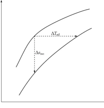
- The Magnetocaloric Effect
- Active Magnetic Regenerators
- Performance Parameters of Active Magnetic Regenerators
- Overview on Magnetocaloric Refrigerator Prototypes
The efficiency of the magnetic cooling system is highly dependent on the efficiency of the regenerative matrix. Another parameter that strongly influences the performance of AMR is the MCE itself (ENGELBRECHT; BAHL, 2010).
Performance comparison between cooling technologies
A key fact to be learned from these works is that none of them - like most of the work reported in the literature - tested their devices with a cabinet as a refrigerated environment and a real heat exchanger in the cold side. Also, most works control the regenerator inlet temperature on the hot side, which does not really reflect a real application of magnetic cooling devices such as refrigerators. Therefore, as advanced as the knowledge of AMR and magnet design is, there is still a lack of knowledge on the behavior of the system operating with a real cabinet and real heat exchanger, and how close magnetic cooling is to vapor compression technology.
If it is assumed that the refrigerator is ideal, inside and outside, the coefficient of performance depends only on the temperatures of the internal and external environments - TC and TH, and is equal to the CarnotCOP presented in Eq. The ideal internal COP is the maximum coefficient of performance that can be achieved by the refrigerator when working with real heat exchangers.
COLD ENDHOT END
If it is assumed that the cooling device works ideally between the cold and hot points —TCE and DIE, the COP considering only thermal losses due to the external irreversibilities can be calculated as follows in Eq. 2.15) where the ii index stands for internal ideal.
T CETC
Conventional wine cooler characterization
- Product description
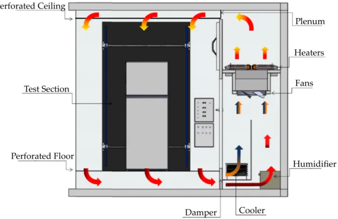
- Cabinet instrumentation
- Test chamber
- Temperature Pull Down Test
- Energy Consumption Test
- Reverse Heat Leakage Test
- Conventional Wine Cooler Thermodynamic Analysis
The instrumentation of the enclosure was installed according to the IEC standard for domestic refrigeration appliances. For household refrigerators, the standard recommends following the product's climate classification. The energy consumption is then calculated by integrating the product's power consumption over the entire test period.
The thermodynamic performance of the conventional wine cooler is evaluated in terms of the coefficient of performance (COP), the overall second law efficiency (η2nd) and the internal and external portions (η2nd,i and η2nd,e). Q˙C =UAup(Tamb−Tup)+UAlow(Tamb−Tlow) (3.3) The total power is calculated with the average of the voltage and the electrical product in periodic steady state.

Magnetic wine cooler development
- AMR/Magnet System
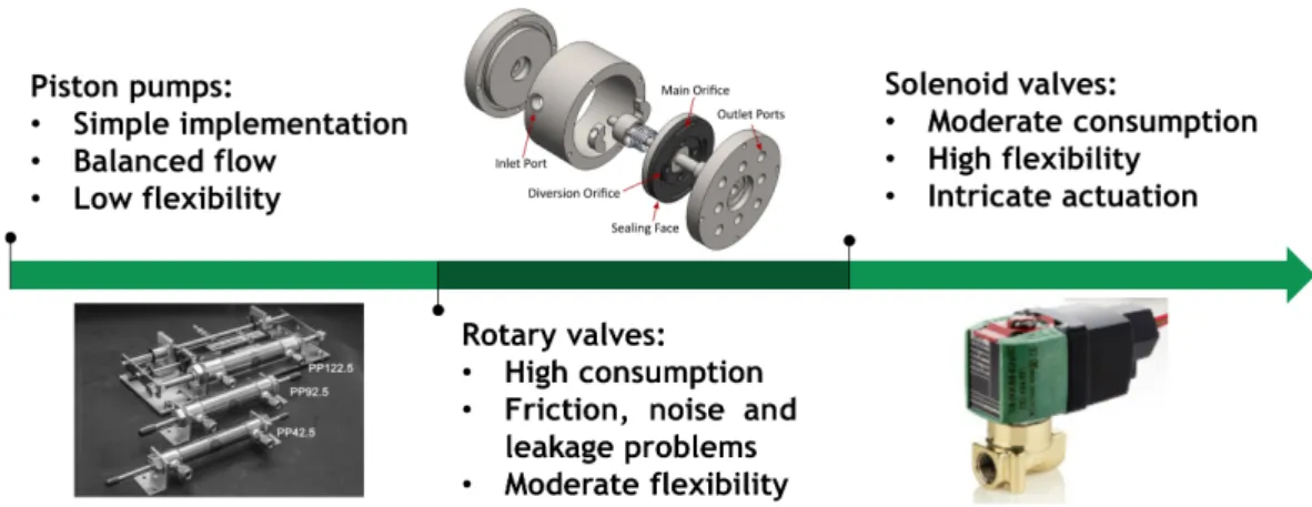
- Hydraulic/Control System
- Cabinet/Heat Exchangers System
- Experimental Apparatus
- Experimental Procedure
A more detailed description of the PoloMag project and magnetic subsystems for wine cooling can be found in the work of Nakashima et al. The main components of the AMR/magnet assembly are presented in the figure. Figure 20 – Exploded view of the first prototype. The logic of assembling 2/2 valves with regenerators is further presented in Fig. 27 in the section.
The blowing fraction is the ratio of the blowing period in a regenerator to the cycle period. The input variables of the test are then the operating frequency and the volumetric flow rate.

- Magnetic Wine Cooler Thermodynamic Analysis
The thermodynamic efficiency of the magnetic wine cooler is evaluated according to the coefficient of performance (COP) and the second law of efficiency (η2nd). COP is the ratio between the cooling capacity and the total energy consumption of the system. Thus, the COP is calculated as presented in Eq. 3.6) where ˙WP, ˙WMo, ˙WCF, ˙WHF and ˙WV are the energy consumption of the pumping system, magnetic rotating system, cold fan, hot fan and valves.
The power consumption of the cold and hot fans as well as the valves is calculated from the measured current and voltage values. 5 The efficiency of the electric motor driving the magnetic system is based on catalog information.
Conventional Wine Cooler Characterization
- Temperature Pull Down Test
- Energy Consumption Test
- Reverse Heat Leakage Test
- Conventional Wine Cooler Thermodynamic Analysis
- Uncertainty Analysis
The second of the basic characterization tests was the assessment of annual energy consumption. 7, based on the extrapolation of the power consumption of the integrated product during a test period of 5 hours. 35 (b) presents the analysis of the external, internal and overall second-law efficiency for the two test points of the conventional wine cooler.
The low efficiency of the heat exchangers may also be due to the compressor being too large. The results of the thermodynamic analysis of the conventional wine cooler are summarized in Tab.

Magnetic Wine Cooler Characterization
- Performance Tests
- Temperature Pull Down Test
- Influence of the Cold Fan Power Test
- Uncertainty Analysis
- Evaluation of Improvement Points
This discrepancy is due to the influence of the ambient temperature on the steady state case temperature. The contribution of each share of energy consumption is also evaluated as a function of flow rate and operating frequency, as shown in Fig. Figures 43 (a) and (b) represent the Carnot and internally ideal COPas function of flow rate and operating frequency.
Figures 44 (a) and (b) present the second-law and internal-external efficiencies as a function of flow rate and operating frequency. 4.1) where ˙Wviscis the viscous power and ˙Qdis the heat dissipation of the pump in the working fluid.

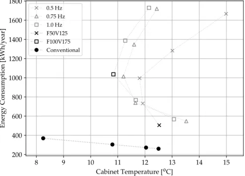
Performance Comparison
The best second-law efficiency of the magnetic wine cooler, 1.7%, was about 46% lower than the second-law efficiency of the conventional wine cooler for a cabinet temperature of 12oC, 3.1%. These results show how much greater the internal irreversibilities and losses of the magnetic wine cooler are compared to the conventional one. The COP and second-law efficiency results of the magnetic wine cooler were all inferior to those of the conventional wine cooler.
The best second-law efficiency of the magnetic wine cooler was about 46% lower than the second-law efficiency of the conventional wine cooler, around a cabinet temperature of 12oC. The shutdown time for the magnetic wine cooler was five times higher than for the conventional one, 5 hours and 1.1 hours respectively.
Recommendations for future works
Sensitivity Study of Multilayer Active Magnetic Regenerators Using First Order Magnetocaloric Material La(Fe,Mn,Si)13Hy.Journal of Applied Physics, American Institute of Physics Inc., v. Influence of Flow Velocity Waveform and Mass Imbalance on the Performance of Active Magnetic Regenerators. Performance evaluation of an active magnetic regenerator for refrigeration applications part I: Experimental analysis and thermodynamic performance. International Journal of Refrigeration, v.
Evaluation of demagnetization phenomena in the performance of an active magnetic regenerator. International Journal of Refrigeration, v. Magnetocaloric properties of spheroidal La(Fe,Mn,Si)13Hy granules and their performance in epoxy-bonded active magnetic regenerators.Applied Elvi Thermal Engineering, Ltd, v.
Theoretical Definitions
This appendix presents the uncertainty analysis of the characterization tests for both the conventional and the magnetic wine cooler, based on the works of Boeng (2012) and Thiessen (2015). When a variable measured indirectly - obtained by a combination of direct variables, the random uncertainty can be derived from the general expression of the uncertainty propagation, such as:.
Uncertainties of the Conventional Wine Cooler Tests
Uncertainties of the Magnetic Wine Cooler Tests
The thermocouples and the pressure transducers uncertainties are the maximum uncertainties obtained during the calibration of those sensors, which is performed internally in the Polo laboratory. The expanded uncertainties were calculated as described in the previous section, as a combination of type A and B uncertainties, for all the performance tests of the magnetic. This appendix presents the analysis of the entropy generation of the prototype and the components of the Hydraulic/Control subsystem.
A further estimated analysis on the entropy generation of the remaining subsystems and its components is proposed and evaluated, to get a sense of possible additional critical points in the contribution of the system inefficiency.
Evaluation of the Hydraulic / Control Subsystem
The term∆h/THS is from Eq. B.5 as there were no temperature measurements between the components, which limits the assessment of the working fluid enthalpy. The flowmeter was installed between the pump outlet and the HHEx inlet, and since the pressure and temperature measurements were not at the exact inlet and outlet of the flowmeter, the entropy generation due to heat losses (˙Qloss,FM) of the tube . was also considered. B.6) The heat losses from the tube to the external environment were calculated as presented in Eq. Applying the experimental data of the F50V125 test condition in the equations described above, the result of the entropy generation of the Hydraulic/Control subsystem.
The Hydraulic/Control subsystem contributes to 69% of the total entropy generation of the magnetic wine cooler, with 45% due to the pump, 16% due to the valves and filter and 8% due to the flow meter. The remainder was attributed to the sum of the contributions from the AMR/Magnet and Cabinet/HEx subsystems.
Estimation of the Entropy Generation of other Subsys- tems
- AMR/Magnet
- Cabinet/HEx
The entropy generation of the magnet is due to the mechanical losses of its drive system to the external environment. The power consumption of the drive system is due to the magnetic interaction and transmission losses. To characterize the entropy generation of the propulsion system, the transmission loss force (˙WTr) must be separated from the magnetic interaction force (˙WMag), by Eq.
Due to limitations in the prototype instrumentation, the temperature and entropy variation of the magnetocaloric material could not be assessed. Considering all transmission losses as heat rejection to the external environment, the entropy generation of the magnet was calculated using Eq.
Overall Evaluation of the Entropy Generation
The pump, the fans and the valves should be addressed first when considering the improvement of the inefficiency of the magnetic wine cooler, since together they represent 78% of the total entropy generation of the prototype. Also, the entropy generation of the valves must be evaluated without the influence of the filter, to identify if the valves are indeed one of the. However, the shares of entropy generation of the components and the subsystems could change if the entropy generation evaluation were more accurate.
The entropy generation of the CHEx, HHEx and the fans can be improved with a characterization in a wind tunnel, to determine the airflow rates of the fans and the pressure drop in the fans and the HExs. With the pressure drop and air flow rates, the efficiency of the fans could also be calculated.