Study on Effect of Thickness and Fibre Orientation on a Tensile
and Flexural Properties of a Hybrid Composite
Mr. Santhosh Kumar. M
1, Dr. S. G. Gopala Krishna
2, Dr. Rajanna. S
3 Dept of Mechanical engineering. NCET. BangalorePrincipal. NCET. Bangalore
Associative prof. Government engineering college. Kushalnagar.
ABSTRACT
This project presents the study of tensile, flexural & moisture absorption properties of composites made from S-glass, Carbon and E-glass fibre. The specimens are prepared using hand lay-up techniques as per ASTM standard for different thickness 2mm and 3mm and fibre orientation of 30º, 45º and 60º, where an attempt is made to study the properties of composite materials by composing the different materials together to obtain the desired properties by increasing the thickness and fibre orientation. By the variation of thickness tensile strength of hybrid composite is observed for each thickness and is compared with the finite element analysis results. The test ready specimens were subjected to tensile and flexural loads on UTM. This research indicates that tensile strength is mainly dependent on the fiber orientation & thickness of laminated polymer composites. The moisture absorption increases with the fibre, filler content and duration of immersion in water.
I.
INTRODUCTION
In the past few decades, research & engineering interest has been shifting from monolithic materials to reinforced materials .the glass and carbon fibers are being used as reinforced materials in reinforced plastics (FRP). This FRP’s have been. widely accepted as materials for structural & non-structural applications. The main reason for the interest in FRP is due to their high stiffness to weight ratio and high strength to weight ratio compared to conventional materials. However, these materials have some drawbacks such as renew ability, recyclability, disposal and expensive. The demand for improved performance of these structural materials makes it necessary to evaluate these materials under multi-axial loading. Fiber reinforced composites show strong anisotropic mechanical behavior due to their fiber orientations. These orientations cause a variety of failure mechanisms, which are more complex under multi-axial loading conditions[1].
Since early 1960s, there has been an increasing demand for materials that are stiffer and stronger yet lighter in fields as aerospace, energy and civil construction and the popularity/usage of bi-woven composites having glass and carbon fibers as reinforcement has been increased in such fields due to their lower production costs, light weight, higher fracture toughness, low thermal expansion, corrosion resistance and better control over the thermo-mechanical properties[2].By choosing an appropriate combination of reinforcement and matrix material, manufactures can produce properties that exactly fit the requirement for a particular structure for a
particular purpose. Composite material systems result in a performance unattainable by the individual constituents and they offer the great advantages of flexible design. Most of efficient design of, say an aerospace structure, an automobile, a boat or an electric motor, we can make a composite material that meets the need. Glass fibre reinforced resins have been in use since about the 1940s.
Glass fibre reinforced resins are very light and strong materials, although their stiffness is not very high. Composite materials are engineering materials made from two or more constituents that remain separate and distinct on a macroscopic level while forming a single component. It consists of a matrix and reinforcement; matrix is bulk of a material holding the reinforcement together in position and help in transferring the loads[3]. The demand for improved performance of these structural materials makes it necessary to evaluate these materials under multi-axial loading. Fiber reinforced composites show strong anisotropic mechanical behavior due to their fiber orientations. These orientations cause a variety of failure mechanisms, which are more complex under multi-axial loading conditions. Therefore, continuous effort has been made to make quasi-isotropic composite materials with controlling parameters, such as the orientation of adjacent plies, the stacking sequence and the properties of the constituents. Several researchers found that bending strength was greater than tensile strength in polymeric composite materials. Wisnom reported in his review that the ratios between 3-point flexural strength and tensile strength of different composite materials were in the range of 1.3–1.49.The majority
of engineering composites materials in demanding applications consist of continuous fibers of glass or carbon reinforcement in thermosetting epoxy polymer. There has been a tremendous advancement in recent days. Compared to metals, the polymeric composites have many advantages as higher fatigue strength, higher corrosion resistance and lower weight[4,5] polymeric composites are susceptible to mechanical damages when they are subjected to efforts of tension, flexural, compression which can lead to material failure. Therefore it is necessary to use materials with higher damage tolerance & carryout an adequate mechanical evaluation.
Damage tolerance of epoxy polymeric composites can be enhanced by improving the interlaminar properties by toughening matrix [6], reinforcement with bidirectional woven fabrics [7,8].
The basic concepts of composites material along with details of earlier works are explained by author at reference [8].The author investigated the influence of different sized glass fibers on the mechanical properties of glass fiber epoxy resin composites. The compressive experimental study to identify the effects of fiber cross sectional aspect ratio on tensile & flexural properties and failure modes of glass fiber/epoxy composites by using fibers of different cross sectional shapes was carried out by authors[9,10].Author[11] investigated the influence of fiber orientation and fiber content of epoxy resin. components on mechanical prosperities. The main aim of the present investigation was to study the influence of fiber orientation on tensile properties and also the influence of thickness of the specimen.
II.
EXPERIMENTAL PROCEDURE
2.1 Materials:
Fig.1: Carbon Fibres Fig.2: Glass Fibres
Carbon fibres are a new breed of high-strength materials as shown in Fig.1. In 1958, Dr. Roger Bacon created high-performance carbon fibers at the Union Carbide Parma Technical Center, located outside of Cleveland (United States), Ohio. Those fibers were manufactured by heating strands of rayon until they carbonized. Carbon fibre has been described as a fibre containing at least 90% carbon obtained by the controlled pyrolysis of appropriate fibres. Fig. 2 shows the Glass Fibres. When these fibres are reinforced with the matrix material(epoxy) forms a strong, lightweight material having many uses, including boats, water tanks, roofing, pipes, automobile bodies and cladding. These two fibres are reinforced in epoxy matrix forming a Bi Woven Fabric. These Bi woven fabrics provide greater
damage tolerance and increased popularity in different applications. The present investigation carried contained a glass fibre of 200 gsm, carbon fibre of 200 gsm and epoxy resin YD128 and hardener HY140 mixed in appropriate ratio with room temperature curing cycle of 48 hours duration.
2.2 Specimen Preparation.
Fig.3(a) & (b):Sample preparation
The laminates were fabricated by placing the glass fiber fabrics and Carbon fibre fabrics one over the other with a matrix in between the layers. These fabrics are stacked layer by layer of about 8,11 layers to attain the thickness of 2mm,3mm respectively as per the ASTM Standard Specimen. Bonding agent (epoxy resin) is applied to create bonding between 8 and 11 layers of sheet, in the ratio of 100:10. Tools were used to distribute resin uniformly, compact plies and to remove entrapped air. The surfaces of the laminates were covered with 25 micron Mila film to prevent the layup form external disturbances. The laminates were cured in room temperature and at
constant pressure for two days. The laminates were cut to suit ASTM dimension by a band saw cutter and edges were ground.
All composites were processed such that fiber fraction was greater than the epoxy resin. For the purpose of investigation 3 different orientation and two different thicknesses were selected. Thickness selected were 2mm and 3mm. The fiber orientation selected for the experimentation was ±30º, ±45º, ±60º. For the purpose of varying the volume fraction of the specimens, the number of carbon and glass fabric layers was varied from 8 to 11.
Fig.4: Standard Tensile Test Specimen Dimensions as per ASTM D - 3039
Fig.5: Standard Flexural Test Specimen Dimensions as per ASTM D - 2344
The tensile and flexural properties of the glass fiber reinforced polymer composites were determined according to standard test specifications of ASTM 3039 and ASTM 2344 [12] respectively. The average
2.3 Specimen Calculation for the Preparation of Laminates
Table.1: Specimen Calculation for the Preparation of Laminates
The Table.1 shows the Specimen Calculation for the Preparation of Laminates for required thickness of 2mm and 3mm respectively.
III.
RESULTS AND DISCUSSION
3.1 Tensile Test
Tensile test is one of the fundamental mechanical tests which is required to evaluate the strength of any material, where a carefully prepared specimen is subjected to tensile load in a controlled manner.
Tensile properties can be measured by the relation of load applied on the material to deflection (Strain) experienced against the applied load. Tensile tests are used to determine the modulus of elasticity. The Tensile tests were carried out in Universal Testing Machine. The specimens were clamped and tests were performed. The tests were closely monitored and conducted at room temperature. The load at which the completed fracture of the specimen occurred has been accepted as breakage load.
Fig 6(a): Load vs Displacement for 2mm thickness at
30º orientation
Fig 6(b): Load vs Displacement for 2mm thickness at 30º orientation
Fig 7(c): Load vs Displacement for 2mm thickness at
30º orientation
Fig 7(d): Load vs Displacement for 2mm thickness at 45º orientation
0 0.5 1 1.5 2 2.5 3 3.5 4
0 5 10 15
Load
i
n
KN
Disp in mm
0 0.5 1 1.5 2 2.5 3 3.5 4
0 5 10 15 20
L
o
a
d
in K
N
Displacement in mm
0 0.5 1 1.5 2 2.5 3 3.5 4 4.5
0 5 10 15 20
L
o
a
d
in K
N
Displacement in mm
0 0.5 1 1.5 2 2.5 3 3.5 4 4.5
0 10 20 30
L
o
a
d
in K
N
Disp in mm Required
Thickness
Number of carbon fibre layers
No of S-glass fibre layers
No of E-glass fibre layers Total Thickness
2mm 2 layers 2*0.22= 0.44mm
3 layers
3*0.2= 0.6mm
3 layers 3*0.2= 0.6mm
0.44+0.6+0.6 =1.66mm 3mm 3 layers 3*0.22=
0.66mm 4 layers
4*0.2= 0.8mm
4 layers 4*0.2= 0.8mm
Fig 7(e): Load vs Displacement for 2mm thickness at
45º orientation
Fig 7(f): Load vs Displacement for 2mm thickness at 45º orientation
Fig 7(g): Load vs Displacement for 2mm thickness at
60º orientation
Fig 7(h): Load vs Displacement for 2mm thickness at 60º orientation
Fig 7(i): Load vs Displacement for 2mm thickness at
60º orientation
Fig 7(j): Load vs Displacement for 3mm thickness at 30º orientation
0 0.5 1 1.5 2 2.5 3 3.5 4 4.5
0 10 20 30
L
o
a
d
in K
N
Disp in mm
0 0.5 1 1.5 2 2.5 3 3.5 4 4.5
0 10 20 30
L
o
a
d
in K
N
Disp in mm
0 0.5 1 1.5 2 2.5 3 3.5 4 4.5
0 5 10 15 20
L
o
a
d
in K
N
Disp in mm
0 0.5 1 1.5 2 2.5 3 3.5 4 4.5
0 5 10 15 20
Load
i
n
KN
Disp in mm
0 0.5 1 1.5 2 2.5 3 3.5 4 4.5
0 5 10 15 20
Load
i
n
KN
Disp in mm
0 1 2 3 4 5 6 7 8 9
0 5 10 15
Load
i
n
KN
Fig 7(k): Load vs Displacement for 3mm thickness at
30º orientation
Fig 7(l): Load vs Displacement for 3mm thickness at 30º orientation
Fig 7(m): Load vs Displacement for 3mm thickness
at 45º orientation
Fig 7(n): Load vs Displacement for 3mm thickness at 45º orientation
Fig 7(o): Load vs Displacement for 3mm thickness at
45º orientation
Fig 7(p): Load vs Displacement for 3mm thickness at 60º orientation
0 1 2 3 4 5 6 7
0 10 20 30
Load
i
n
KN
Disp in mm
0 1 2 3 4 5 6 7 8
0 5 10 15 20
Load
i
n
k
n
Disp inmm
0 0.5 1 1.5 2 2.5 3 3.5 4 4.5
0 5 10 15
Load
i
n
k
n
Disp in mm
0 1 2 3 4 5
0 10 20 30
Load
i
n
k
n
Disp in mm
0 1 2 3 4 5 6
0 5 10 15 20
Load
i
n
KN
Disp in mm
0 1 2 3 4 5 6 7
0 5 10 15 20
Load
i
n
k
n
Fig 7(q): Load vs Displacement for 3mm thickness at
60º orientation
Fig 7(r): Load vs Displacement for 3mm thickness at 60º orientation
Table 2: Tensile properties of Carbon and S-glass and E-glass fiber reinforced polymer composites Sample
thickness (mm)
Fiber orientation
(degrees)
Maximum breakage load (KN)
Ultimate tensile strength
(N/mm2) Avg
Young’s
Modulus (N/mm2) Avg
% of elongation
Avg
2 30 3.64 75.86 968.21 10.64
3 30 7.2 93.15 1073.08 13.3
2 45 4.16 60.88 647.82 15.73
3 45 4.5 80 769.87 15.97
2 60 3.84 76 789.15 12.51
3 60 6.58 85.82 1021.81 12.61
The load v/s displacement graphs of the tensile test for the 2mm and 3mm thickness hybrid laminates were plotted as shown in Fig.6 (a) to Fig.6(i). The curves show a steep linear increase up to a point where the specimens tends break suddenly. The
Values of the Ultimate tensile strength, Young’s
Modulus are tabulated in Table 2.
3.2 Flexural Testing
Flexural strength is the ability of the material to withstand bending forces applied Perpendicular to its
longitudinal axis. Sometime it is referred as cross breaking strength where maximum stress developed when a bar-shaped test piece, acting as a simple beam, is subjected to a bending force perpendicular to the bar. There are two methods that cover the determination of flexural properties of material: three-point loading system and four point loading system. Three-point loading system applied on a supported beam was utilized. Flexural test is important for designer as well as manufacturer in the form of a beam.
Fig 8(a): Load vs Displacement for 2mm thickness at 30º orientation
Fig 8(b): Load vs Displacement for 2mm thickness at 30º orientation
0 1 2 3 4 5 6 7 8
0 5 10 15
Load
in
kn
Disp in mm
0 1 2 3 4 5 6
0 5 10 15 20
Load
i
n
k
n
Disp in mm
0 0.05 0.1 0.15 0.2 0.25
0 10 20 30
Load
i
n
KN
Disp in mm
0 0.05 0.1 0.15 0.2 0.25
0 10 20 30
Load
i
n
KN
Fig 8(c): Load vs Displacement for 2mm thickness at 30º orientation
Fig 8(d): Load vs Displacement for 2mm thickness at 45º orientation
Fig 8(e): Load vs Displacement for 2mm thickness at 45º orientation
Fig 8(f): Load vs Displacement for 2mm thickness at 45º orientation
Fig 8(g): Load vs Displacement for 2mm thickness at 60º orientation
Fig 8(h): Load vs Displacement for 2mm thickness at 60º orientation
0 0.05 0.1 0.15 0.2 0.25
0 10 20 30
Load
i
n
KN
Disp in mm
0 0.02 0.04 0.06 0.08 0.1 0.12 0.14 0.16 0.18 0.2
0 10 20 30
Load
i
n
KN
Disp in mm
0 0.02 0.04 0.06 0.08 0.1 0.12 0.14 0.16 0.18 0.2
0 10 20 30
Load
i
n
KN
Disp in mm
0 0.02 0.04 0.06 0.08 0.1 0.12 0.14 0.16 0.18 0.2
0 10 20 30
Load
i
n
KN
Disp in mm
0 0.02 0.04 0.06 0.08 0.1 0.12 0.14 0.16
0 5 10 15 20
Load
i
n
KN
Disp in mm
0 0.02 0.04 0.06 0.08 0.1 0.12 0.14 0.16
0 10 20 30
Load
i
n
KN
Fig 8(i): Load vs Displacement for 2mm thickness at 60º orientation
Fig 8(j): Load vs Displacement for 3mm thickness at 30º orientation
Fig 8(k): Load vs Displacement for 3mm thickness at 30º orientation
Fig 8(l): Load vs Displacement for 3mm thickness at 30º orientation
Fig 8(m): Load vs Displacement for 3mm thickness at 45º orientation
Fig 8(n): Load vs Displacement for 3mm thickness at 45º orientation
0 0.02 0.04 0.06 0.08 0.1 0.12 0.14 0.16
0 10 20 30
Load
i
n
KN
Disp in mm
0 0.05 0.1 0.15 0.2 0.25 0.3 0.35 0.4
0 10 20 30
Load
i
n
KN
Disp in mm
0 0.05 0.1 0.15 0.2 0.25 0.3 0.35 0.4 0.45
0 5 10 15 20
Load
i
n
KN
Disp in mm
0 0.05 0.1 0.15 0.2 0.25 0.3 0.35 0.4
0 5 10 15 20
0 0.05 0.1 0.15 0.2 0.25 0.3 0.35 0.4
0 10 20 30
Load
i
n
KN
Disp in mm
0 0.05 0.1 0.15 0.2 0.25 0.3 0.35
0 10 20 30 40
Load
i
n
KN
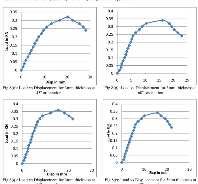
Fig 8(o): Load vs Displacement for 3mm thickness at 45º orientation
Fig 8(p): Load vs Displacement for 3mm thickness at 60º orientation
Fig 8(q): Load vs Displacement for 3mm thickness at 60º orientation
Fig 8(r): Load vs Displacement for 3mm thickness at 60º orientation
The load v/s displacement graphs for the Flexural test of the 2mm and 3mm thickness hybrid laminates were plotted as shown in Fig.7(a) to Fig.7(i). The resulting curves show an initial increase
and beyond a certain point there is a linear increase in curve up to the maximum stress where the component fails. The Values of the Ultimate tensile
strength, Young’s Modulus are tabulated in Table 3.
Table 3: Flexural properties of Carbon and S-glass and E-glass fiber reinforced polymer composites Sample
thickness (mm)
Fiber orientation
(degrees)
Flexural Stress in Mpa Avg
Flexural modulus in Mpa Avg
2 30º 263.15 6241.26
3 30º 213.87 4309.01
2 45º 236.84 4635.13
3 45º 190.55 2636.96
2 60º 202.22 5234.76
3 60º 184.21 3479.35
IV.
CONCLUSIONS
Experiments were conducted on bi directional woven fabric S-glass, Carbon and E-glass composite specimens with varying thickness and fibre
orientation to evaluate the tensile, bending properties. The experimental results clearly indicate that
a) Increase in thickness of laminates tends to increase the tensile strength. Load required to fracture the specimen completely depends on the thickness. If 0
0.05 0.1 0.15 0.2 0.25 0.3 0.35
0 10 20 30
Load
i
n
KN
Disp in mm
0 0.05 0.1 0.15 0.2 0.25 0.3 0.35 0.4
0 5 10 15 20 25
0 0.05 0.1 0.15 0.2 0.25 0.3 0.35 0.4
0 10 20 30
Load
i
n
KN
Disp in mm
0 0.05 0.1 0.15 0.2 0.25 0.3 0.35 0.4
0 10 20 30
L
o
a
d
i
n
KN
thickness increases by 1 mm then 40 to 50% more load is required for fracture and the tensile strength is superior in case of 30º orientation.
b) % of elongation and Young’s modulus increases
with increase in thickness in tensile test. c)
Increase of the flexural stress, young’s modulus with
decrease in thickness.
d) More loads are required for fracture of laminates in case of 90º orientations. More elongation is observed in 45º orientation. The elongation is
minimal in case of 30º orientation. Young’s modulus
is more in case of 30º orientations.
e) Increase of the flexural stress and young’s modulus with decrease in thickness.
REFERENCES
[1] B.H.Manjunath, Dr. K Prahlada Rao,
“Influence Of Fiber/Filler Particles
Reinforcement On Epoxy Composites”,
International Journal of Engineering Research and Applications (IJERA), Vol. 3, Issue 3, May-Jun 2013, pp.1147-1151. [2] Prashanth Banakar , H.K. Shivananda and
H.B. Niranjan, “Influence of Fiber Orientation and Thickness on Tensile
Properties of Laminated Polymer
Composites”, Int. J. Pure Appl. Sci.
Technol., 9(1) (2012), pp. 61-68.
[3] Mr. M. Nayeem Ahmed, Dr. P. Vijaya Kumar, Dr. H.K. Shivanand, Mr. Syed Basith Muzammil4 ,”A Study on Effect of Variation of Thickness on Tensile Properties of Hybrid Polymer Composites
(Glassfibre-Carbonfibre-Graphite) and GFRP
Composites”, International Journal of
Engineering Research and Applications (IJERA), Vol. 3, Issue 4, Jul-Aug 2013, pp.2015-2024.
[4] M.M. Schwartz,Composite Materials: Properties, Nondestructive Testing and
Repair, V.1, Prentice- Hall Inc., New Jersey,
USA, 1997.
[5] A.A. Baker, P.J. Callus, S. Georgiadis, P.J. Falzon, S.E. Dutton and K.H. Leong, An
affordable methodology for replacing
metallic aircraft panels with advanced
composites, Composites: Part A, 33(2002),
687–696.
[6] N. Selaand and O. Ishai, Interlaminar fracture toughness and toughening of
laminated composite materials: A review,
Composites, 20(20) (1989), 423–425. Int. J. Pure Appl. Sci. Technol., 9(1) (2012), 61-68. 68
[7] A. Mouritz, K. Leong and I. Herszberg, A review of the effect of stitching in the in plane mechanical properties of fiber
reinforced polymer composites, Composites:
Part A, 28(12) (1997), 979–991.
[8] B.S. Hayes, E.N. Gilbert and J.C. Seferis,
Scaling complications of dual temperature cure resin prepreg systems in airplane part
manufacture, Composites: Part A, 31(2000),
717–725.
[9] D.M. Issacand and O. Ishai, Engineering
mechanics of composite materials, Oxford
University Press, Oxford.
[10] S. Deng, L. Ye and Y.W. Mai, Influence of fiber cross-sectional aspect ratio on mechanical properties of glass fiber/epoxy
composites, Tensile and flexure behavior,
Composite Science and Technology, 59(1999), 1331–1339.
[11] K.M. Kaleemulla and B. Siddeswarappa,
Influence of fiber orientation on the in-plane mechanical properties of laminated hybrid
polymer composites, Journal of Reinforced
Plastics and Composites, 29(12) (2009). [12] ASTM, Standard test method for tensile
properties of polymer matrix composite
materials, ASTM D3039, Annual Book of
ASTM Standards, American Society for Testing and Materials, PA, 15(03) (2003). [13] Keshavamurthy Y C , Dr. Nanjundaradhya
N V , Dr. Ramesh S Sharma, Dr. R S
Kulkarni “Investigation of Tensile Properties of Fibre Reinforced Angle Ply
laminated composites” ISSN 2250-2459,
Volume 2, Issue 4 April 2012.
[14] GuruRaja M. N, A. N. HariRao. “Hybrid
Effects on Tensile Properties of
Carbon/Glass Angle Ply Composites”.