22
Scientific Bulletin of the „Petru Maior” University of Tîrgu Mureş Vol. 13 (XXX) no. 2, 2016
ISSN-L 1841-9267 (Print), ISSN 2285-438X (Online), ISSN 2286-3184 (CD-ROM)
DIDACTIC SYSTEM FOR THE EXPERIMENTAL STUDY
OF DIGITAL PID CONTROL STRUCTURES
Stelian-Emilian OLTEAN
1, Mircea DULĂU
2, Adrian-Vasile DUKA
3 1,2,3Petru Maior University of Tirgu-Mures Nicolae Iorga st., no. 1, Tirgu-Mures, 540088, Romania 1
[email protected], [email protected], [email protected]
Abstract
The proportional integral derivative (PID) controller has a known structure used in feedback control of industrial processes. One of the most common applications is the control of the DC motor. The paper presents a didactic system designed for educational purposes used for studying various conventional PID structures and the influence of the PID components in the control process of the DC motor’s speed. The system contains a low cost acquisition board based on PIC 16F628A microcontroller. The experimental results are shown graphically using a PC application made in Matlab environment.
Key words: didactic system, digital PID control, dc motor speed control, PIC microcontroller.
1. Introduction
Control systems lectures are part of the curriculum of higher education institutes offering degrees in engineering (especially in control or electrical engineering, electronics and mechatronics). The main controllers presented in these lectures contain the proportional, integral or/and derivative components (continuous time or discrete time). Moreover, most of the industrial control applications are using PID controllers, whether we speak about positioning, speed, temperature, pressure, level, flow or other physical variables [8,11,12].
Although PID control structures are well known, understanding their operation and components actions represent difficult tasks for beginners and the use of some educational units helps a lot. This paper proposes such a didactic system for studying different PID control actions on dc motor’s speed.
Mathematical models of the dc motor and PID controllers are presented in [8,11,12] and also simulations of the designed feedback control systems which show the influence of the PID components on dc motor speed can be found in [6], [17] and [21].
The authors of [9] analyse the dc motor speed control under varying load conditions. The authors of [1] and [2] compare the performances of the conventional control with fuzzy logic control, while [3] and [16] propose the use of fuzzy logic for the automatic tuning of the PID parameters. The available results were obtained in Matlab and Labview programming environments.
Besides theoretical studies, for educational purposes it is more attractive to test different conventional control structure on physical processes. In [5] is presented an implementation of an analogue PID controller for the speed control of a dc motor using operational amplifiers. Today's spread of the microcontrollers enable low cost implementation of flexible digital control structures.
Sometimes, the digital controllers (on/off, PID or other type) are programmed directly on the data acquisition boards. In [10] and [14] the PIC microcontroller contains the temperature controller and the PC is used just for monitoring and configuring the overall system, locally or remotely via a server-client application.
In other practical applications [13] and [20], microcontroller based acquisition boards (based on Arduino or PIC microcontrollers) are used as interface modules to the computer. In these situations, the PID controller is implemented on the computer and the graphical user interface, done in Matlab or Labview allows easy user access to the system components.
23 Compared to the more expensive units available on the market, this work describes a low cost didactic system and some practical experiments for teaching the concepts of PID control of DC motor speed control. The PID control structures are implemented in Matlab environment on a PC and the user has some experimental options.
2. Didactic system
The didactic system consists of five main hardware components:
- personal computer, running Matlab environment; - electronic interface with PIC microcontroller; - power supply (6V..15V);
- rotary incremental encoder for the motor speed; - dc motor.
The block diagram of the didactic system is shown in fig. 1.
Fig. 1: Block diagram of the didactic system
Different programming languages and virtual instrumentation environments could be used for monitoring, graphical visualization of functional signals and for interacting with various components of the speed control system. In this educational kit, Matlab was chosen due to its powerful toolboxes for numerical computing, modelling and simulation of dynamic systems. Matlab is a multi-domain environment and fourth-generation programming language developed by MathWorks for matrix manipulations, plotting of functions and data, implementation of algorithms, creation of user interfaces, and interfacing with programs written in other languages [18]. Moreover, Matlab contains also an additional package, Simulink, which is a graphical multi-domain simulation environment and model-based design for dynamic systems.
The implemented software application offers the beginner user options: to view the functional signals, select different digital PID structures, access and tune their parameters. An advanced user could modify the control algorithm; test his knowledge of control engineering or teaching/learning other concepts such as analogue electronics, digital electronics, control systems, microcontrollers, programming and systems identification due to interdisciplinary character of the overall system.
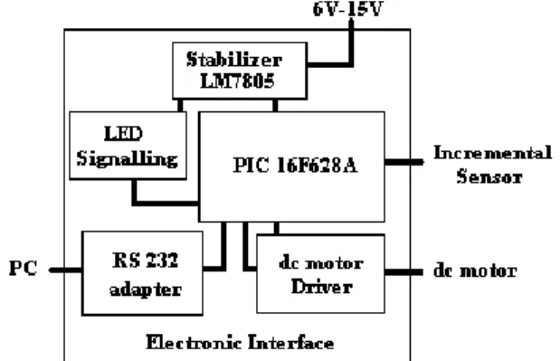
An important part of the didactic system is the electronic interface module (low cost acquisition board) based on PIC microcontroller. This interface
measures the angular speed of the shaft by counting the pulses coming from the incremental sensor and provides the PWM signal to the dc motor according to the control algorithm implemented in Matlab.
The block diagram of the electronic interface is shown in fig. 2.
Fig. 2: Block diagram of the electronic interface
The main unit of the electronic interface is the PIC16F628A microcontroller. PIC16F628A is an eight bit CMOS microcontroller with high performance RISC CPU and Harvard architecture. It has the following features: 16 I/O pins with individual direction control, analogue comparator module, 3 timers (two 8 bit timers and one 16 bit), capture, compare, PWM module, USART serial module and selectable oscillator options.[19]
The electronic interface contains five modules: - constant voltage regulator module made with LM7805 integrated circuit;
- RS 232 serial communication module; - DC motor driver module;
- signalling module with two LEDs;
- the PIC16F628A microcontroller is used as PWM signal generator and for computing the angular speed of the dc motor.
The microcontroller’s program implements two main functions. The first function is to compute the angular speed of the dc motor using the analogue signal from the incremental sensor and the second function is to command the dc motor via the driver module, with a PWM signal. The angular speed and PWM duty cycle represent the process value and control value of the overall control system. These eight bit values are serial transmitted or received to/from the PC, via RS 232 adapter.
For the serial communication a software protocol with two messages is implemented:
a) angular speed message
b) PWM duty cycle command message
24
n
F
T
osc
upd
4
255
255
1
(1)
For the oscillating frequency of Fosc=11.0592MHz
and n=5, the angular speed updating period Tupd is
0.11759s and the microcontroller sends to the PC the computed value in the angular speed message. The PC software application uses this message as current process value in the control algorithm.
One cycle is completed when the PC responds with the current control value in the PWM duty cycle command message according to the control algorithm. The microcontroller generates a PWM signal and, using the driver module, modifies the angular speed of the DC motor. The generated PWM signal frequency is computed based on:
PWM PWM osc PWM T F prescaler T PR T / 1 4 ) 1 2 ( (2)
Using a 1:16 prescaler for Timer 2 and PR2=255, a resulting 750Hz PWM frequency TPWM is obtained.
The serial communication between the PC and electronic interface uses 115200bps baud rate, one byte of date, one stop bit and no flow control. In Matlab, a function creates the software serial object to access the serial communication.
3. Mathematical models
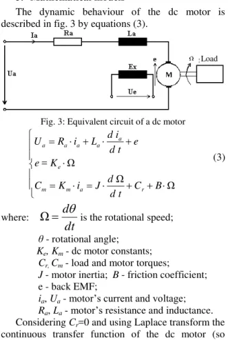
The dynamic behaviour of the dc motor is described in fig. 3 by equations (3).
Fig. 3: Equivalent circuit of a dc motor
Ω Ω Ω = B C t d d J i K C K e e t d i d L i R U r a m m e a a a a a (3) where:
dt
d
Ω
is the rotational speed; θ - rotational angle;Ke, Km - dc motor constants;
Cr, Cm - load and motor torques;
J - motor inertia; B - friction coefficient; e - back EMF;
ia, Ua - motor’s current and voltage;
Ra, La - motor’s resistance and inductance.
Considering Cr=0 and using Laplace transform the
continuous transfer function of the dc motor (so called input output model) is given by equation (4). For this model, the input is the supply voltage and the
output is the rotational speed [7].
)
)(
(
)
(
sJ
B
sL
R
K
K
K
U
s
H
a a m e ma
(4)In the design procedure it is necessary to introduce also the other elements (transducer, converters, driver), which mathematically are represented by theirs transfer functions. The overall plant model could be simplified and then digitized using the zero order hold (ZOH) method for simulations. These calculations are known, taught and used in the simulation part of the educational study, but are not presented in this paper.
In the simulation part of the control laboratory different continuous or discrete PID control structures (e.g. standard form, series form, filtered form, and parallel form) are studied. The industrial PID controllers currently are achieved using digital information processing equipments [12]. The digital control algorithm on these equipments computes the command based on the measured functional signals, sampled, codified and digitized.
One way to design a digital PID controller is to make a continuous-time design and then transform this to discrete-time approximation. In this way, the digital PID controller should behave as the continuous-time system.
However, the following part will present only the mathematical equations that are experimentally tested in this paper using the didactic system. All the digital PID control algorithms are obtained by digitizing the standard continuous form [8,11]:
(5)
where the Kp, Ti, Td are the PID control constants;
u(t) is the control signal and ε(t) is the control error between the setpoint and the process value.
The discrete-time PID control law based on the backward rectangular method (known also as Euler’s method) of discretization is given in (6).
0 2 0 1 0 0 0 2 1 0 , 2 1 , 1 ) 1 ( ) 2 ( ) 1 ( ) ( ) ( T T K q T T K q T T T T K q k u k q k q k q k u d P d P d i
P
(6) where T0 - the sample period;
q0, q1, q2 - the controller coefficients;
u(k) - control value at sample moment k; ε(k) - control error at moment k.
The discrete-time PID control law based on the forward rectangular method of discretization is given in (7).
25 0 2 0 0 1 0 0 2 1 0 , 2 1 , 1 ) 1 ( ) 2 ( ) 1 ( ) ( ) ( T T K q T T T T K q T T K q k u k e q k e q k e q k u d P d i P d
P
(7) The discrete-time PID control law based on the trapezoidal method (known also as Tustin method) of discretization is given by (8).
0 2 0 0 1 0 0 0 2 1 0 , 2 2 1 , 2 1 ) 1 ( ) 2 ( ) 1 ( ) ( ) ( T T K q T T T T K q T T T T K q k u k e q k e q k e q k u d P d i P d i P (8)
4. Experimental results
The main goal of using this experimental setup for educational study is to help the users understand how the digital PID controller is functioning and how do the different components of the control structure influence the system. The author’s work experience has proven that this method is better preferred and more attractive to students.
Above of all, learning through experiments, in case of the dc motor speed control system, supposes a manual tuning of a PID controller. To achieve all of the comparative experiments the following were considered: 20 seconds total time, a step input signal, 0.1 second sampling time and 8 bits digital representation of the functional signals (setpoint, control error, PWM control signal, process value).
The procedure of manually tuning consists in the gradual introduction of the three components fo the controller (proportional component P, then the integral part I and finally the derivative component D) and studying their influence on the system's response.
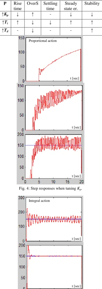
Figures 4 and 5 present experimental results of manual tuning the PID controller (digitized with the backward rectangular method). Table 1 contains the tuning values of the PID controller’s constants.
Table 1: PID tuning values for control law (6)
Ex 1 2 3 4 5 7 8 9
Kp 1 2 3 0.5 0.5 0.5 0.5 0.5
Ti - - - 0.5 1 1 1 2
Td - - - 0.1 1 1
The step responses obtained during the tuning procedure of the digital PID control parameters show that the effects of the PID components are similar to those produced in the continuous case. Table 2 highlights the main effects produced by the components of the digital PID controller.
Table 2: Effects of increasing the PID components (↑ and ↓ means an increase or decrease of the parameter)
P Rise time
OverS Settling time
Steady state er.
Stability
↑Kp ↓ ↑ - ↓ ↓
↑Ti ↑ ↓ ↓ ↑ ↑
↑Td - ↓ - - ↑
Fig. 4: Step responses when tuning Kp.
26 Fig. 5: Step responses when tuning Ti and Td.
After the adjustment experiments for the PID constants, the following values can be chosen:
Kp=0.5, Ti=2 şi Td=1. These values assure a maximum
of 5% overshoot, a settling time less than 2 seconds (20 samples for 0.1 sampling time), a rise time less than 1 second and zero steady state error. The setpoint and process value, PWM control value and control error signal are shown in fig. 6.
Fig. 6: Functional signals (backward discretization).
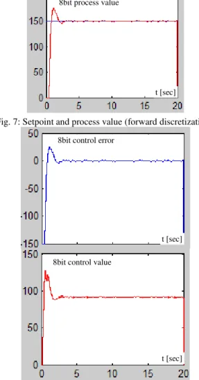
The experimental results obtained after doing the same tuning procedure for the other two digital PID structures (digitized with the forward rectangular or trapezoidal methods) were similar to those presented at the beginning of this section.
For the control structure given in (7) and using the same PID constants that assure the imposed performance the functional signals are shown in fig. 7 and 8.
Fig. 7: Setpoint and process value (forward discretization).
Fig. 8: Error and control signal (forward discretization).
For the control structure given in (8) the functional signals are shown in fig. 8.
t [sec]
t [sec] t [sec]
t [sec] t [sec]
t [sec]
t [sec] t [sec] t [sec] t [sec] Derivative action
8bit process value
8bit control error
8bit control value
8bit process value
8bit control error
8bit control value
27 Fig. 9: The functional signals (trapezoidal discretization).
5. Conclusions
This paper presented a didactic system for studying PID control structures applied for dc motor speed control.
The industrial processes use digital PID controllers, therefore, an important part of the feedback control lectures are related to these structures. Using didactic systems such as this for training purposes has proved its worth. This kit was well received by the students, who were able to test various control algorithms, understand their operation and the action of the controller’s components. The graphically user interface in Matlab allows monitoring, configuring and interacting with the components of the overall system.
The experimental setup is very flexible and contains an electronic interface module which is a low cost acquisition board based on PIC microcontroller. The interdisciplinary character of this system makes it usable for learning other concepts like: analogue electronics, digital electronics, control systems, microcontrollers, programming, and systems identification.
Acknowledgement
This paper is based upon work supported by the Energy and Electrotechnologies Management research center, Department of Electrical and Computer Engineering, “Petru Maior” University of Tîrgu-Mureş.
References
[1] Adewuyi, P.A. (2013), DC Motor Speed Control: A Case between PID Controller and Fuzzy Logic Controller, International Journal Of Multidisciplinary Sciences And Engineering, Vol. 4, No. 4, pp. 36-40.
[2] Aydemir, S., Sezen, S. and Ertunc, H.M. (2004), Fuzzy logic speed control of a DC motor , The 4th International Power Electronics and Motion Control Conference, pp. 766 - 771.
[3] Bansal, U.K. and Narvey, R. (2013), Speed Control of DC Motor Using Fuzzy PID Controller, Advance in Electronic and Electric Engineering, Volume 3, Number 9, pp. 1209-1220.
[4] Batista, F.A.B., Petry, C.A., Santos, E.L.F. and Almeida, B.R. (2009), Didactic system for digital control of power electronics applications,
Brazilian Power Electronics Conference 2009, Bonito-Brazil, pp. 1093-1098.
[5] Bhagat, N.A. and Bhaganagare, M. (2009), DC Motor Speed Control using PID Controllers, EE 616 Electronic System Design Course Project, EE Dept, IIT Bombay.
[6] Dash, B. and Vasudevan, V. (2011), GUI/Simulink Based Interactive Interface for a DC Motor with PI Controller, International Journal of Scientific & Engineering Research, Vol. 2, Issue 12, pp. 1-5.
[7] Dulau, M. and Oltean, S. (2011), Systems modelling and simulation, (Romanian version: Modelarea şi simularea sistemelor), Ed. Univ. Petru Maior, Tg Mureş.
[8] Isermann, R. (1992), Digital Control Systems, vol II, Berlin, Springer Verlag.
[9] Khan, M.R., Khan, A.A. and Ghazali, U. (2015), Speed Control of DC Motor under Varying Load Using PID Controller, International Journal of Engineering, Vol. 9 (3), pp. 38-48. [10] Levărdă, B. and Budaciu, C. (2010), The design
of temperature control system using Pic18f4620,
Buletinul Institutului Politehnic din Iasi, Tomul LVI, Fasc. 4, pp. 203-214.
[11] Norman, N. (2008), Control Systems Engineering, 5th ed., John Wiley and Sons. [12] Ogata, K. (2009), Modern Control Engineering,
4th ed., Dorling Kindersley Pvt, Ltd.
[13] Oltean, S. and Morar, A. (2006), Direct Digital Self-Tuning Controllers with Minimum Variance. Practical Implementation for an DC Motor, Acta Electrotehnica, Vol. 47, No. 3, pp. 168-173.
[14] Oltean, S., Abrudean, M. and Dulau, M. (2006), Remote monitor and control application for thermal processes using TCP/IP, AQTR 2006, pp. 1-5.
[15] Patané, E.J., Assis, W.O., Coelho, A.D. and Rezek, A.J.J. (2009), A didactic speed control system of dc motors Based on data acquisition system, 20th International Congress of
Mechanical Engineering, Gramado-Brazil,
pp.1-10.
[16] Salim, J.O. (2015), Fuzzy Based PID Controller for Speed Control of D.C. Motor Using Labview, Wseas Transactions On Systems And Control, Vol. 10, pp. 154-159.
[17] Singh, A.P., Narayan, U. and Verma, A. (2013), Speed Control of DC Motor using Pid Controller Based on Matlab, Innovative Systems Design and Engineering, Vol.4, pp. 22-28. [18] The Mathlab website (2016). [Online].
Available: http://www.mathworks.com.
28 [20] Vikhe, P., Punjabi, N. and Kadu, C. (2014), Real
Time DC Motor Speed Control using PID Controller in LabVIEW, International Journal of Advanced Research in Electrical,Electronics and Instrumentation Engineering, Vol. 3, Issue 9, pp. 12162-12167.