A R C H I V E S
o f
F O U N D R Y E N G I N E E R I N G
Published quarterly as the organ of the Foundry Commission of the Polish Academy of Sciences
ISSN (1897-3310)
Volume 10
Issue Special1/2010
395-398
77/1
The application of optical measurements for
the determination of accuracy of gear wheels
casts manufactured in the RT/RP process
G. Budzik
a, M. Oleksy
b, M. Grzelka
c, M. Wieczorowski
c, M. Magniszewski
d, J. Slota
e aDepartment of Machine Design, Rzeszów University of Technology, Al. Powsta
ń
ców Warszawy 8, 35-959 Rzeszów
b
Cathedral of Technology and Chemical
Science of
Materials, Rzeszów University of Technology
c
Institute of Mechanical Technology, Poznan University of Technology
d
Jednostka Wojskowa 35-33, Wysoka G
ł
ogowska
e
University of Technology in Kosice
*e-mail: gbudzik@prz.edu.pl, molek@prz.edu.pl, miroslaw.grzelka@gmail.pl
Received 05.03.2010; accepted in revised form 23.03.2010
Abstract
The article discusses the possibilities of using optical measurements for defining the geometric accuracy of gear wheels casts manufactured in the rapid prototyping process. The tested gear wheel prototype was cast using an aluminum alloy.The casting mouldwas made by means of the three-dimensional print method(3DP) with the use of a Z510 Spectrum device. The aim of the tests was to determine the geometric accuracy of the cast made by the ZCast technology in the rapid prototyping process. The tests were conducted with the use of the coordinate optical measuring method and a GOM measuring device. The prototype measurements were made in the scanning mode. The results of the measurements, saved in the STL format with the use of the scanning device software, were compared with the gear wheel 3D-CAD nominal model. The measurements enabled the determination of the real accuracy of prototypes manufactured in casting moulds by means of the ZCast technology.The selection of the measuring method was also analyzed in terms of measurement accuracy and the RP technology precision.
Key words: optical measurements, Rapid Prototyping, geometric accuracy, gear wheels
1. Introduction
Rapid prototyping (RP) and rapid tooling (RT) systems are increasingly used in the production of casting components.RP systems can be used directly for manufacturing casting moulds [1-9].The spectrum of rapid prototyping uses can be expanded by the application of the rapid tooling methods. One of the RT techniques is the direct manufacture of casting moulds using the ZCast technology. The accuracy of gear wheels casts made in printed mouldsdepends ona variety of technological factors [10-13]. The accuracy of the cast fabrication quality can be assessed with the use of the coordinate optical measuring technique [14-16]. Literature describes the methods for manufacturing moulds in
the ZCast technology, usually omitting the aspect of their dimensional and shape accuracy. It is for this reason that the article seeks to explore this theme.
2. Cast manufacturing
2.1. Casting mould 3D-CAD model
The first stage of manufacturing the casting mould was the creation of a gear wheel 3D-CAD model. Next, the gear model was supplemented with a gating system.The mould shape and its parting plane were defined. The last operation was the removal of the gear wheel model and the gating system from the mould solid. This way, a
two-part mould 3D-CAD model was made (fig. 1), which was saved in the STL format.
Fig. 1. Mould 3D-CAD model
2.2. Casting mould manufacturing
The mould was made with the application of the three-dimensional print method, using a Z510 Spectrum device. The mould was hardened with epoxide resin in the process of infiltration.
Fig. 2. Casting mould made by the 3DP method
2.3. Cast manufacturing
The preparation of the casting process included heating the mould in 70°C, which caused water to evaporate. Next, the mould parts were joined together and filledwith an aluminum alloy. After the alloy solidified, the mould was broken and the cast cooled (fig. 3).
Fig. 3. Gear wheel cast
3. Measurements
3.1. Preparing the measuring device
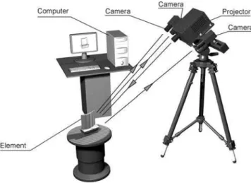
The measurements of the gear wheel cast accuracy were made with the use of the optical coordinate scanner (fig. 4). The average accuracy of the measuring method was 6 µm.
Fig. 4. View of the measuring position
Before taking the measurements, an anti-reflection coating was applied on the tested gear wheel. The thickness of the coating ranged from 0,8 µm do 1,2 µm. The measurements were taken at the Institute of Metrology and Measuring Systems, at Poznań University of Technology.
The methodology of the testsconsisted in scanning the gear wheel cast and comparing the surface received as a result of the measurements with the 3D-CAD model. Next, the real deviations of the cast shape were defined at all points with reference to the nominal CAD model for the purpose of determining the real model construction accuracy.
3.2. Analysis of Measurements Results
Optical measurement enables a precise recreation ofthe geometry of complex-shaped objects and the scanner specialised softwaremakes it possible to compare the measurement results with the 3D-CAD mathematical model. The ATOS scanner specialised software allows for a full metrological analysis of the measurement results. At the first stage of the measurements results analysis, the gear wheel cast surface image was compared with the casting mould 3D-CAD model (fig. 5). Next, the measurements results were compared with the gear wheel 3D-CAD nominal model (fig. 6).
Fig. 5. View of an ATOS window
Fig. 6. Spatial map of cast deviations
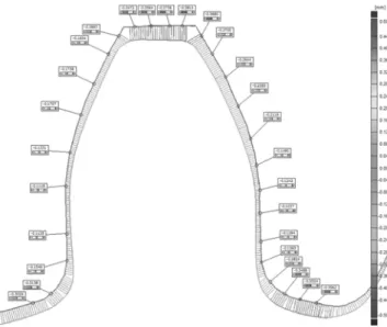
Displayed in the software window is a spatial three-dimensional map of the measured gear wheel deviations relative to the nominal model. An analysis was carried out of the deviation values at the selected points of the cast longitudinal section (fig. 7) and at the selected points of the toothed wheel rim section (fig. 8).
Fig. 7. Deviations at the points of the cast longitudinal section
Fig. 8. Gear wheel cast tooth form deviations
4. Conclusions
The coordinatemeasuring technique enabled the assessment of the dimensional and shape accuracy of casts manufactured with the application of the rapid prototyping process. The measurements results show that there is a significant difference between the cast real dimensions and the nominal dimensions. The discrepancy stems largely from casting shrinkage. The casting mould was made based on the gear wheel 3D-CAD nominal model. The measurements results indicate that casting moulds manufactured with the use of the 3DP method should be individually modified based on the measurements results, applying the coordinate measuring technique. The information from the measurements allows for the definition of the compensation coefficients, which should be taken into consideration while constructing the 3D-CAD model. The coordinate optical measuring method ensured a sufficient accuracy of the casts evaluation, a short measurement-taking phase and fast results processing.
Acknowledgements
Financial support of Structural Funds in the Operational Programme - Innovative Economy (IE OP) financed from the European Regional Development Fund - Project "Modern material technologies in aerospace industry", No POIG.0101.02-00-015/08 is gratefully acknowledged.
References
[1] N. Homburg, E. Wellbrock, Knowledge - Based manufacturing strategy and methods for foundries, Conference and Exhibition for Rapid Technology, Erfurt 2006.
[2] R. Hartym, Dimensional accuracy of investment casting for the burned pattern process, Archives of Foundry, Volume 6, No18 (2/2), (2006) 231-236 (in Polish).
[3] R. Haratym, J. Tomasik, The influence of ceramic mould quality on surface geometry of al investment casting, Archives of Foundry, Volume 6, No18 (2/2), (2006) 237-242 (in Polish).
[4] D. Myszka, J. Modzelewski, M. Leśniwski, A. Kerwiński, Introduction to titanium investment casting as implants use, Archives of Foundry, Volume 6, No18 (2/2), (2006) 237-242 (in Polish).
[5] A. Gebhardt, Rapid Prototyping, Carl Hanser Verlag, Munich 2003.
[6] T. Wohlers, Wohlers Report 2009 – State of the Industry, Annual Worldwide Progress Report. Wohlers Associates Inc., Fort Collins, CO, USA 2009.
[7] I. Gajdoš, J. Slota, E. Spišák, FDM prototypes virtual modeling, ICAT 2008, 2nd International Conference on Additive Technologies: DAAAM Specialized Conference:
September 17th -19th, 2008, Ptuj, Slovenia: Proceedings. Vienna: DAAAM International, 3 p. ISBN 3-901509-72-0 [8] G. Budzik, Possibilities of utilizing 3DP technology for
foundry mould making, Archives of Foundry Engineering, Vol. 7, Issue 2/2007, s. 65-68.
[9]W. Liu, Rapid Prototyping and engineering applications – a toolbox for prototype development, Taylor & Francis Group, 2008.
[10]J.C. Feriera, E. Santos, H. Madureira, J.Castro, Integration of VP/RP/RT/RE/RM for rapid product and process development, Rapid Prototyping Journal Vol. 12 No. 1/2006, Emerald 2006, 18-28.
[11]M. Oleksy, M. Heneczkowski, G Budzik, Composities of unsaturated polyester resins applied in Vacuum Casting technology, POLIMERY 2008, 53, nr 2, s. 60-63.
[12]G. Budzik, Properties of made by different methods of RP impeller foundry patterns, Archives of Foundry Engineering, Vol. 7, Issue 2/2007, s. 83-86.
[13]G. Budzik, T. Markowski, M.Sobolak, Hybrid foundry patterns of bevel gears. Archives of Foundry Engineering, Vol. 7, Issue 1/2007, s. 131-134.
[14]PN-EN ISO 10360-5:2003 Geometrical Product Specifications (GPS). Acceptance and reverification tests for coordinate measuring machines (CMM). Part 5: CMMs using multiple-stylus probing system (in Polish).
[15]M. Grzelka, Possible applications of the optical coordinate scanner GOM ATOS II, Coordinate Measuring Technique. Problems and implementations. University of Bielsko-Biala 2008
[16]E. Ratajczyk, Coordinate measuring technique, Oficyna Wydawnicza Politechniki Warszawskiej, Warszawa 2006 (in Polish).