Abstract—Modern digital communications favor OFDM systems because of their advantages such as spectral efficiency, reduced inter-symbol interference (ISI) and flexibility of deployment across various frequency bands with little modification to the air interface. One of the principle challenges of OFDM systems is the cost and complexity of the system implementation. Recent developments in the field of digital electronics and Software Defined Radio have opened up various possibilities of simplified solutions for such complexities. Field Programmable Gate Arrays (FPGA) provide a perfect platform for this purpose because of their low-cost, easy programmability and vast resources. This work presents a simplified design and FPGA implementation of an OFDM system specified by the European Telecommunications Standard Institute (ETSI) for satellite digital radio in ETSI TS 102 551-2 V2.1.1 (2007-08), using Xilinx DSP design tools.
Index Terms—FPGA, OFDM, ETSI, Satellite Radio, SDR.
I. INTRODUCTION
Satellite digital radio, following its vast success in North America is becoming increasingly popular in Europe and other parts of the world. There is however, a constant demand for spectral efficiency and high quality of data in such systems. OFDM transmission is often the preferred choice for digital audio and video broadcasting. The ETSI radio interface standard for Satellite Digital Radio systems, ETSI TS 102 551-2 V2.1.1 (2007-08), which provides specifications of the inner physical layer with multiple carrier transmission (IPL-MC), uses OFDM transmission [1].
Many of these newly developed standards as one mentioned above are still being subjected to development and deployment. It is quite a challenging task to build a suitable hardware platform that would have fast and intense processing capabilities, support high data rates, flexible and reprogrammable. Moreover, the hardware complexity involved in such systems can raise the operational cost significantly. Field Programmable Gate Arrays (FPGA) offers a low-cost, off-the-shelf hardware platform for such
Manuscript received June 29, 2010. This work was supported in part by TRLabs, Canada.
Anh Dinh is with the Department of Electrical and Computer Engineering, University of Saskatchewan, Saskatoon, Canada. (phone: 306-966-5344; fax: 306-966-5407; e-mail: [email protected]).
Suranjana Julius is with the Department of Electrical and Computer Engineering, University of Saskatchewan, Saskatoon, Canada. (e-mail:
standards. The fast processing capabilities, vast resources, easy programmability and low cost make FPGAs a perfect platform for systems based on Software Defined Radio concept.
Several studies have been done over the years towards the implementation of OFDM systems. Some work have been reported regarding FPGA implementation of OFDM systems based on standards for Wireless Local Area Network (WLAN), Worldwide Interoperability for Microwave Access (WiMAX) etc. In [2], Sghaier, Areibi and Dony describe design comparison and implementation details of an OFDM system based on IEEE802.16-2004 for WiMAX on a Xilinx FPGA using two different design tools. The same authors report in [3] work done based on IEEE802.11a standard for WLAN. Also in [4], Garcia and Cumplido report the work done towards design and implementation of the OFDM based on IEEE802.16-2004.
In this paper, a fixed point design of an OFDM system is described using Xilinx System Generator tool for DSP design and implementation details on the Virtex-4 SX35 Xilinx FPGA. The OFDM transmitter is based on the technical specification provided by ETSI TS 102 551-2 V2.1.1 (2007-08) standard for Satellite Digital Radio. The baseband I and Q data generated by the OFDM system can be used for further signal processing. One of the objectives of this work is to demonstrate that the FPGAs with advanced Digital Signal Processing (DSP) capabilities such as Xilinx Virtex-4 SX family can support design and implementation complexity of systems based on standards such as ETSI Satellite Digital Radio. Another objective is to show that advanced DSP design tools such as Xilinx System Generator makes complex designs simple by offering integration between MATLAB coding, VHDL coding, IP cores, SIMULINK and Xilinx design blocks in a graphical environment.
The paper is divided into six sections. Section 2 reviews the principles of OFDM, Section 3 provides a brief description of the ETSI TS 102 551-2 V2.1.1 (2007-08) standard, Section 4 discusses the methods used, Section 5 describes the design based on Xilinx System Generator, Section 6 discusses results of implementation on Virtex-4 SX35 FPGA and Section 7 concludes this paper
II. BASICS OF OFDMMODULATION
The fundamental principle of OFDM originated from Chang in 1966. The serial data stream of a fast traffic
Suranjana Julius and Anh Dinh
Fixed Point Design and Implementation of an
OFDM Transmitter for ETSI Satellite Digital
Radio on FPGA Platform
Proceedings of the World Congress on Engineering and Computer Science 2011 Vol II WCECS 2011, October 19-21, 2011, San Francisco, USA
ISBN: 978-988-19251-7-6
ISSN: 2078-0958 (Print); ISSN: 2078-0966 (Online)
channel is passed through a serial to parallel converter which splits the data into N number of slower rate parallel channels. The data in each channel is applied to a modulator, such that for N channels there are N modulators whose carrier frequencies are f0, f1,…, fN-1. The difference between the adjacent channels is f and the overall bandwidth W of the system is N f. The N modulated carriers are combined to give an OFDM signal. At the receiver, the OFDM signal is de-multiplexed into N frequency bands and the N modulated signals are demodulated. The baseband signals are then recombined using a parallel to serial converter.
The high data rate in such system is achieved by splitting the data traffic into a number of slower rate channels instead of using a high data rate single channel. The orthogonality of the sub-carriers allows overlapping without interference, thereby providing better spectral efficiency compared to a traditional Frequency Division Multiplexing (FDM). To avoid ISI, a guard interval is inserted before each OFDM symbol. Appropriate choice of a guard interval length can remove ISI. The guard interval comprises of a sequence of all zero samples (zero-prefix) or the last few samples of the OFDM symbol (cyclic-prefix). The cyclic-prefix insertion results in the removal of intra-symbol interference by making the OFDM symbol appear periodic. The redundant samples from the guard interval are discarded at the receiver.
In practice, the OFDM systems are realized using a combination of FFT (Fast Fourier Transform) and IFFT (Inverse Fast Fourier Transform) modules. The incoming data stream is bit-mapped into constellation such as QAM, QPSK etc. and then applied to the IFFT module as a frequency-domain data. The IFFT module takes N symbols at a time and performs IFFT and the output data is a time-domain signal. The FFT module performs the demodulation of the OFDM signal in the receiver end.
III. ETSI102551-2V.2.1.1(2007-2008)STANDARD
The ETSI technical specification ETSI TS 102 551-2 V2.1.1 (2007-08) [1] is a standard for Satellite Digital Radio systems. It covers the Inner Physical Layer of radio interface with Multiple Carrier Transmission (IPL-MC). The standard uses OFDM scheme of modulation.
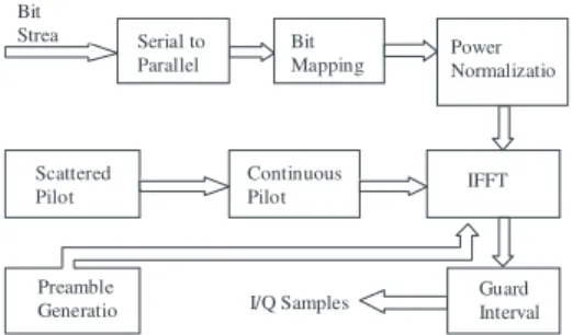
In this work, the specifications given by Mode 3 with OFDM at 1k (i.e., 1024 FFT length) with 1.7 GHz channel spacing have been used as a reference to model a fixed-point, FPGA-based OFDM system. Fig. 1 shows an OFDM transmission based on the Mode 3 specifications described in the document. The OFDM parameters in Mode 3 are listed in Table 1.
IV. APPLIED METHODOLOGY
The process of designing the OFDM system model included two steps. The first step was to develop and test the model structure in floating point using MATLAB version 2007a. The output was verified and analyzed. The next step was to develop a fixed point equivalent of the model that would be suitable to be contained completely in an FPGA starting from data generation to the OFDM output samples.
The graphical design environment chosen was Xilinx System Generator 10.1 for Windows XP SP3 which is a DSP design tool from Xilinx. System Generator offers a complete integration platform for MATLAB codes, VHDL codes, Xilinx ISE 10.1 IP cores and SIMULINK and Xilinx design blocks. Xilinx ISE simulator was used to verify the design of each component and also the complete system. Xilinx System Generator developed a fixed point system that was imported as a Xilinx ISE foundation project and implemented on a Virtex-4 SX35 FPGA.
Fig. 1 OFDM transmission based on ETSI Standard
Table 1: ETSI TS 102 551-2 Mode-3 OFDM parameters
Parameter Unit Value
Modulation Index 4
FFT Length 1024
Used Sub-carriers 729
Guard Interval Ratio 1/4
Sampling Frequency MHz 2.1511
Pilots per OFDM symbol 127
Sub-carrier distance KHz 2.10
Signal Bandwidth MHz 1.5314
V. DESIGN FLOW
The Xilinx System Generator design flow can be divided into four subsections: Random data generation, constellation mapping, pilot generation, preamble generation, interleaving and pulse shaping of the data, IFFT and cyclic prefix adding. All the components blocks use 16-bit fixed point representation with binary point at 14. The output samples are clocked at 2.1511Msps.
A. Random Data Generation
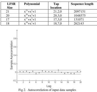
The first component in the design is a random data generator. This module uses Linear Feedback Shift Register (LFSR) IP cores from Xilinx. Each LFSR generates a Pseudo Random Binary Sequence (PRBS). Four LFSRs of Galois type having 20, 21, 17 and 18 bits were used in parallel to maximize the PRBS sequence. Two-input XOR gates were used for the feedback taps. The polynomials equations and the feedback tap location of the LFSRs are given in Table 2. The generated sequence is of length 2LFSR-SIZE-1.
The output of each LFSR was generated serially. Fig. 2. shows the autocorrelation of the generated sequence. The serial output sequences were fed in parallel to a scrambler block to maximize the length of the generated sequence. The serial output of the scrambler block was grouped according to the selected modulation scheme. The grouped bits were treated as input symbol in frequency domain and were used to perform constellation mapping.
Bit
Mapping Power Normalizatio
IFFT
Guard Interval I/Q Samples
Preamble Generatio Scattered Pilot
Continuous Pilot Bit
Strea Serial to
Parallel
Proceedings of the World Congress on Engineering and Computer Science 2011 Vol II WCECS 2011, October 19-21, 2011, San Francisco, USA
ISBN: 978-988-19251-7-6
ISSN: 2078-0958 (Print); ISSN: 2078-0966 (Online)
Table 2: Galois-type LFSR Specifications
LFSR Size
Polynomial Tap
location
Sequence length
21 x21
+x2
+1 21,2,0 2097151
20 x20+x3+1 20,3,0 1048575
17 x17
+x3
+1 17,3,0 131071
18 x18+x7+1 18,7,0 262143
S
a
mp
le
A
u
to
c
o
rr
e
la
ti
o
n
Lag
Fig 2. Autocorrelation of input data samples
B. Constellation Mapping and Power Normalization
The next step was mapping the bits to the constellation. The available modulation schemes were QPSK, 16-QAM (non-hierarchical), 16-QAM (hierarchical) with constellation scale factor α=2 and α=4.
This part of the design could be realized using various options. To maintain design simplicity and minimizing resource usage, advantage was taken from the Xilinx System Generator’s unique feature that allows simple MATLAB codes to be imported into the design environment. This was achieved by using Xilinx M-code design block while maintaining the fixed point representation of data. Fig. 3 shows the architecture of the Mapper based on Xilinx M-code block. Bit-grouping was performed on the serial bit stream using a multiplexer which outputs I and Q data based on the selected modulation scheme. The output was obtained in the form of I and Q pairs. The Mapper also normalizes the power level of the I and Q output pairs by a scale factor to avoid using multipliers following the mapping. The different scale factors used for the various modulation schemes are given in Table 3.
Fig. 3. Architecture for Mapping to Constellation
C. Pilot Generation
Each OFDM symbol consists of 127 pilots with a pilot density of 17%. There are 112 continuous pilots and 15 scattered pilots. The amplitude of the pilots is 4/3 times that of normalized data sub-carriers and therefore they are “boosted” pilots as compared to the data samples. Each pilot consists of an individual phase as well as group phase. The pilots were first rotated in phase by 0 or π according to their individual phases and then a second rotation was performed
in similar manner according to their group phase. Rotation by 0 or π is equivalent to multiplying each pilot by +1 or -1 respectively. For design simplicity, each generated pilot was pre-multiplied by +4/3 or -4/3. Only one 16 bit x 1024 ROM was required to store the pilots and this was implemented using a Xilinx IP core for single port ROM. The pilots were stored in the specified memory locations of the ROM and additional registers were used for pipelining at the output.
Table 3: Scale Factors for various modulation schemes
Constellation Scale Factor for Normalization
QPSK 1/√2
16QAM(non-hierarchical) 1/√10
16QAM(α=2) 1/√20
16QAM(α=4) 1/√52
D. Interleaving and Pulse Shaping
This step included inter-leaving of data samples, pilots and zero samples and pulse-shaping. The 16-bit I and Q pairs from the constellation mapper output were stored in two separate single ports 16 bit x1024 RAMs. The RAMs were initialized by zeroes and the 729 locations were filled up with data values for the active sub-carriers required by OFDM.
A VHDL code based interleaving module was used for mapping the mapped data samples from the RAM and pilots stored in the ROM in their specific index locations. The interleaving module consisted of a counter running at the sample rate that was used to specify the index locations. Pulse shaping was also performed at this stage. The 729 active carriers were positioned such that the carrier number 364 was at the centre frequency. A multiplexer was used to output the data, pilot and zero samples in accordance with the index counter. The output I and Q samples were subjected to additional pipelining stage before they were passed on to the IFFT block.
E. Pre-amble Generation
The IPL-MC frame sequence as specified by Mode 3 in [1] consists of a frequency-domain preamble followed by a sequence of 120 OFDM symbols. Each preamble symbol is of the same length as the OFDM symbol and the samples have amplitude of 4/3. Therefore to maintain the structure of the IPL-MC frame for the ETSI standard, a 16 bit x 1024 ROM was used to store the samples for the Preamble. The Preamble samples were also rotated by 0 or π according to their phase by pre-multiplying them by +4/3 or -4/3 before storage.The Preamble preceded the sequence of 120 OFDM symbols before they were applied as frequency-domain data input to the OFDM modulator. A counter was used to synchronize the Preamble and the OFDM symbols in the IPL-MC frame.
F. IFFT and Cyclic Prefix Insertion
The final step was the conversion of frequency-domain data samples to time-domain output of an OFDM transmitter. The IFFT block used is a Xilinx FFT/IFFT IP core. The 1024 I/Q pairs were applied to the input of the IFFT block. The algorithm used for the IFFT block performs continuous processing of the input stream instead of working on a whole symbol at once. This maintains a high throughput although increases resource usage.
After a number of latency cycles required by the IFFT block, a continuous streaming of output samples are Proceedings of the World Congress on Engineering and Computer Science 2011 Vol II
WCECS 2011, October 19-21, 2011, San Francisco, USA
ISBN: 978-988-19251-7-6
ISSN: 2078-0958 (Print); ISSN: 2078-0966 (Online)
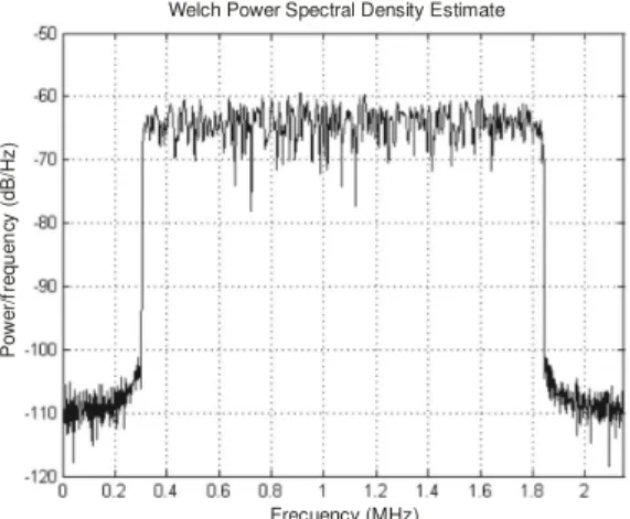
generated and Cyclic Prefix of 256 samples were added. The output of the IFFT block was obtained in the form of OFDM symbols with a guard interval ratio of ¼. A Welch power spectral density was estimated for an OFDM symbol in MATLAB environment and shown in Fig 4.
VI. IMPLEMENTATION RESULTS
This work is aimed at a low-cost reconfigurable platform for implementing the design supported by ETSI standard for Satellite Digital Radio. The design was targeted to a Xilinx FPGA from Virtex-4 Device family XC4SX35F668 of speed grade -10 which is a suitable platform for complex DSP algorithm implementation. The System Generator design was directly imported as a Xilinx ISE Foundation project synthesized and implemented on the Virtex-4 device. This OFDM transmitter was used in conjunction with signal processing modules in a satellite radio transmitter and timing was met at a frequency of 276.48 MHz on the targeted Virtex-4 device. The clock frequency used was 34 MHz which was used to generate a frequency of 2.1511 MHz for the OFDM transmitter.
Welch Power Spectral Density Estimate
P
o
w
e
r/
fr
e
q
u
e
n
cy
(
d
B
/H
z
)
Frecuency (MHz)
Fig. 4. Power Spectrum of ETSI Std. Mode 3 OFDM symbol
The complete resource usage of the OFDM transmitter is given in Table 4. It was noted that the IFFT/FFT block uses the most resource. It was also noted that a significant amount of resources were saved by regenerating and using various IP cores offered by Xilinx. The design can be migrated to other device family such as Spartan-3E, Virtex -II Pro, Virtex-5 with very little or no modification.
Table 4: Resource Usage on Virtex-4 XC4SX35F668-10
Resource Available Used %
Slices 15360 3466 22%
FFs 30720 4702 15%
LUTs 30720 4844 16%
BRAMs 192 9 5%
DSP48s 192 16 8%
Bonded IOBs 34 448 7.6%
GCLKs 4 32 12.5%
DCMs 1 8 12%
Since there are no reports of ETSI SDR TS 102 551-2 V2.1.1 implementation a resource utilization comparison is provided in Table 5 for some similar work based on IEEE802.11a [3] and IEEE802.16 Standard [4]. It is noted
that absolute comparison is not possible because the Standards used in [3] and [4] are different from this work and the design methodology is different in [3]. A pure VHDL based approach has been used in [3] and modulation schemes such as BPSK, QPSK and 16QAM and 64QAM has been used for OFDM transmitter with 64-point FFT and sampling frequency of 20MHz. A Xilinx System Generator based approach similar to this design has been used in [4] and an the OFDM modulator with 256-point FFT with QAM or QPSK modulation has been described.
The comparison with other works related to FPGA implementation of OFDM transmitters using different standards shows that this work using ETSI SDR standard is equally suitable for FPGA implementation because of low resource usage, flexibility and easy transportability of the design to various FPGAs. Furthermore, it is shown that use of DSP slices (DSP48s) in this work has resulted in faster clock rates and higher computational abilities.
Table 5: Resource Usage comparison of [3],[4]& this work.
Resource [3] [4] This work
Slices 3568 2614 3466
FFs 3581 3566 4702
LUTs 6048 4304 4844
LUTs as RAM 820 - -
BRAMs - 12 9
DSP48s - - 16
Mult 18x18 8 - -
Bonded IOBs 39 29 34
GCLKs 6 1 4
DCMs 1 - 1
VII. CONCLUSION
In this paper, a complete design and implementation of an OFDM transmission system compliant with Mode 3 of the ETSI technical specification ETSI TS 102 551-2 V2.1.1 (2007-08) was presented. Also the mapping results on a low-cost reconfigurable platform were presented. The results obtained clearly indicate that it is possible to design and implement complex digital communication standards, using user-friendly DSP design tools. This provides opportunity for future work in design and implementation of the other modes in the above standard and also other standards for satellite radio and other wireless networks.
REFERENCES
[1] ETSI TS 102 551-2 V2.1.1 (2007-08), “Satellite Earth Stations and Systems (SES); Satellite Digital Radio (SDR) Systems; Inner Physical Layer of the Radio Interface; Part 2: Multiple carrier transmission,” France, 2007.
[2] A. Sghaier, S. Areibi, and R. Dony, “IEEE802.16-2004 OFDM functions implementation on FPGAs with design exploration,” in FPL.2008: Proc. of the 2008 International Conference on Field Programmable Logic and Applications, Sept. 2008.
[3] A. Sghaier, S. Areibi, and B. Dony, “A Pipelined Implementation of OFDM Transmission on Reconfigurable Platforms,” in CCECE 2008: Proc. of the 2008 Canadian Conference on Electrical and Computer Engineering, pp. 801-804, May 2008.
[4] J. Garcia and R. Cumplido, “On the design of an FPGA-based OFDM modulator for IEEE 802.16-2004,” in RECONFIG’05: Proc. of the 2005 International Conference on Reconfigurable Computing and FPGAs, Sept. 2005.
[5] Xilinx Inc., www.xilinx.com.
[6] L. Hanzo and T. Keller, OFDM and MC-CDMA: A Primer, John Wiley & Sons Inc., UK, 2006.
Proceedings of the World Congress on Engineering and Computer Science 2011 Vol II WCECS 2011, October 19-21, 2011, San Francisco, USA
ISBN: 978-988-19251-7-6
ISSN: 2078-0958 (Print); ISSN: 2078-0966 (Online)