Intrusion Detection in Wireless Body Sensor
Networks
Nadya
El
MOUSSAID
ESSIlab,IbnZohr University,Agadir Morocco
Ahmed
TOUMANARI,
and
Maryam
EL
AZHARI
ESSIlab, IbnZohrUniversity,Agadir Morocco
Abstract—The recent advances in electronic and robotics industry have enabled the manufacturing of sensors capable of measuring a set of application-oriented parameters and transmit them back to the base station for analysis purposes. These sensors are widely used in many applications including the healthcare systems forming though a Wireless Body Sensor Networks. The medical data must be highly secured and possible intrusion has to be fully detected to proceed with the prevention phase. In this paper, we propose a new intrusion superframe schema for 802.15.6 standard to detect the cloning attack. The results proved the efficiency of our technique in detecting this type of attack based on 802.15.6 parameters performances coupled with frequency switching at the radio model.
Keywords—Intrusion detection; cloning attack; 802.15.6; healthcare; WBSN
I. INTRODUCTION
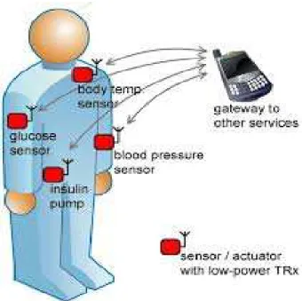
Wireless sensor network (WSN) consists in utilizing homo-geneous or heterohomo-geneous sensor nodes, capable of communi-cating wirelessly in order to forward packets to a centralized base station [1]. A sensor nodes can be either static or dynamic dependently on the application in use [2][3]. In fact, the type of application defines as well the rhythm of data collection which can be performed periodically or upon occurrence of an event. A set of biosensors deployed or implanted in the human body constitutes a subtype of WSN named Wireless Body Area Networks (WBANs) also known as Wireless Body Sensor Networks (WBSNs).The main purpose of this type of network is to measure physiological parameters and for-ward it to the local base station (PDA), which handles the retransmission of data packets to medical centers for analysis and treatment. WBAN has many constraints inherited from Adhoc networks such as: limited energy resource, reduced memory size, small transmission power etc. The biosensor is low-powered devices with miniaturized size that are able to detect medical signal such as: electroencephalography (EEG), electrocardiogram (ECG), blood pressure, insulin etc...(See Fig.1).There exist a various types of monitoring systems being currently used in medical applications. Most of them are based on wired connection which restricts the mobility of the patient [4][5]. To this end, WBAN requires wireless sensor devices communicating wirelessly to a control unit followed with a remote healthcare centers for diagnostic purposes [6][7]. The remainder of this paper is organized as follows: In Section 2, we presented the IEEE 802.15.6 standard. Our proposed intrusion detection schema for 802.15.6 standard was presented in Section 3. The simulation results are depicted and analyzed
in Section 4 and the paper is concluded in Section 5.
Fig. 1. Biosensors distribution in WBSN
II. IEEE 802.15.6 STANDARD
responsible to structure the access to the channel via three access modes:
• Beacon mode with beacon period superframe boundaries. • Non-beacon mode with superframe boundaries.
• Non-beacon mode without superframe boundaries.
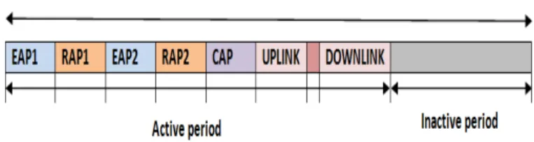
The beacon superframe includes several slots where the first slot is dedicated to beacon packet transmission, which is followed by a flexible diversity of phases that can be defined as: RAP (Random Access Period), EAP (Exclusive Access Period), MAP (Management Access Period) and CAP (Contention Access Period). RAP is used to transmit regular traffic where priority is considered normal (if it is not low). EAP is used to transmit data packets with high priority; uplink and downlink communication can be used during the MAP while the CAP can be activated upon reception of a beacon packet of type B2 from the PDA to complete the transmission of data packets. The CAP, RAP and EAP phases adopt the CSMA/CA mechanism or ALOHA to guarantee a contended access to the channel whilst the MAP resort to polling or posting schema. An example of beacon superframe mechanism is presented in Fig. 2.
Fig. 2. Example of 802.15.6 beacon period
III. INTRUSIONDETECTIONSCHEMA FOR802.15.6 STANDARD
In order to tackle the problem of security in WBSNs, cryptographic protocols can be applied along with 802.15.6-2012 standard. However, some protocols have major secu-rity problems and can be vulnerable to a numerous attacks. Moreover, cryptographic protocols can generate a tremendous energy drain due to intensive computing operations.
To this end, it is very crucial to make a trade off balance between the pros and cons of using such greedy protocols to guarantee the best security service while minimizing the overall energy consumption. Our work sheds the light on the cloning attack, which actually consists in cloning the target sensors and transmitting faulty data to the destination. Such at-tack can affect the performance of 802.15.6-2012, as the cloned sensor will always get access to the channel for it possesses a high priority. In fact, a biosensor with a high priority value is considered transmitting emergent data; therefore, the access to the channel has to be immediate compared with regular data.
This differentiation is highlighted when the CSMA/CA mechanism is employed to regulate the access to the channel. A backoff Counter is selected within a Contention windows intervals which takes into consideration the maximum and minimum value in respect to the measured data. The backoff Counter value is decremented for each idle channel detection performed by Contention Channel Assessment (CCA), when
it reaches a null value, the sensor node can proceed with data transmission.
A cloned sensor can dominate the access to the channel by always choosing a minimum backoff counter value. This will either result in creating collision with intact biosensors or generate faulty data leading to misinterpretation of the measured data. In order to detect this type of attack, we create a new intrusion detection schema for 802.15.6 standard that will supervise the network during each beacon period for abnormal behavior. As previously mentioned, the beacon period is subdivided into several phases, which constitutes the active phase, followed with the inactive period, during which biosensors regain energy batteries units when they are in their idle state. In this work, we proposed a new 802.15.6 standard superframe schema where the inactive period is partially used to insure uplink communication with the local base station (which is in our case represented by the Personal Digital Assistant).
Our new schema consists in performing periodic verifi-cation of possible intrusion during each beacon period (i.e. Beacon mode with beacon period superframe boundaries). The verification is handled by the PDA that will constantly supervise the transmissions at the radio module and detect abnormal behavior. If the former is taking place, a second stage verification is maintained to emphasize the existence of an intrusion by interrogating biosensors for transmitted information using TDMA mechanism. An intrusion is stated to exist if the ratio of packets being received exceeds or falls short of the norm. The functioning mechanism of our intrusion detection schema and its corresponding superframe are presented in Algorithm A and Fig. 1 respectively.
Fig. 3. Intrusion detection superframes for 802.15.6 standard
Our intrusion detection schema is based on supervising the network performance during each beacon interval or beacon period. The beacon period start s off with sending beacons to inform the biosensors about the overall superframe structure but also the different phases that compose it. Therefore, biosensors will be able to wake up during their corresponding time period and switch to sleeping mode to reduce the energy consumption. In our case, before sending the beacon, the local base station has to verify the activity of the network in order to define the superframe structure. An abnormal activity is detected first at the radio module of the base station, which is followed by checking the activity of the other biosensors if an intrusion has certain probability to be taking place. The parameters that are considered by the base station are enumerated as follows:
B RxReachedInterference:refers to the average number of packets received with possible interference.
C RxFailedInterference: indicates the average number of packets failed because of interference.
D RxFailedSensitivity:indicates the average packets recep-tion failure because it is below the receiver sensitivity. E RxFailedNoRxState: refers to the average packets
re-ceived due to the non reception state of the transceiver.
The local base station calculates the Radio Coefficient as defined by:
RadioCoef f icient= P
(A, B, C, D)timex
P
(A, B, C, D)norm
(1)
if the RadioCoefficient value is less than ()0.5,then the local base station will assume that an intrusion exists and will activate both UPLINK and DOWNLINK phases in the superframe as depicted in Fig. 3. The UPLINK phase is dedicated to transmission without contention and using TDMA mechanism. During this phase, each biosensor is affected a miniTimeSlot to transmit information about the overall packet transmission to the base station (PDA). The miniTimeSlot length is chosen to be less than the CSMA/CA contention slot length so that to reduce the transmission delay but also the energy consumption, as the transceiver is reset to sleep mode as soon as the transmission is accomplished. When the packet transmission information is received, the base station will go on with verifying the actual existence of an intrusion. As mentioned in Algorithm A , the term:
kIntrusion coef f iciensi − Intrusion coef f icientni|| ∈ ||Intrusion coef f icientni||+/−threshold index(2)
is calculated upon receiving packets information; the
threshold index represents a certain threshold that will be defined by the user and depend on the parameters to be measured. In other words, the threshold is mainly application oriented. Both Intrusion coef f icientsi and Intrusion coef f icientni vectors are calculated according to an additional parameters from the MAC layer ,which will give us more clues whether or not it pertains to creat-ing packets collision or generatcreat-ing faulty data packets. The Intrusion coef f icientsi vector is defined as follows:
Intrusion coef f iciensi= Success,1st try Success,2 or more tries
Failed,No Ack Failed,Channel busy Fail,buffer overflow (3)
• Success, 1st try:designate the average number of packets being received successfully on the first try.
• Success, 2 or more tries: designate the average number of packets being received successfully on the second or xth try.
• Failed,No Ack: The average number of packets ex-periencing a failure of transmission due to failure of acknowledgement packets reception.
• Failed,Channel busy: The average number of packets failed due to the non availability of the channel.
• Fail,buffer overflow: The average number of packets failed due to the longer storage in the buffer or the lack of buffer space to store the incoming packets from the upper layer.
The threshold index value is defined by:
threshold index=p%∗ ||Intrusion coef f icientsi|| (4)
Where: p% is a percentage defined by the user.
In our case of study, we considered that a biosen-sor is experiencing intrusion if more than 50% of the Intrusion coef f icientsi vector rows values are out of the norm. Similarly, if more than 50% of the biosensors do verify the above condition, then it is claimed the non existence of an intrusion. The base station will then send a packet to inform the biosensors during a minislot located right after the UPLINK phase period; this will allows the biosensors to sleep for the rest of the beacon interval and then conserve a considerable amount of energy. Else if the condition is not verified for more than 50% of the biosensors, then the base station will inform the biosensors of such information during the aforementioned minislot, to keep them in the active state for the DOWLINK period, during which the base station will send the following frequency to use for data transmission. The information about the frequency will be encrypted; hence the cloned sensors are going to be isolated for several beacon periods.
Algorithm 1 Algorithm A
Data:
NBP : Number of beacon periods.
threshold index:the threshold upon which it is assumed the existence of an intrusion.
NS: number of source nodes. possible intrusion exist: vari-able indicating the existence of abnormal activity. It is set to one after detecting a suspicious behavior at the local base station.
forp=1 to NBP do if
kIntrusion coef f iciensi −
Intrusion coef f icientni|| ∈ ||Intrusion coef f icientni||+/−threshold index(5)
then
//Normal behavior.
- Send a notification packet to all biosensors within the first minislot located after the UPLINK phase to deactivate the DONWLINK phase.
else
//Intrusion detected.
- Activate the DOWLINK phase.
- Interrogation for the following frequency to switch to.
end end
manufacturing key linked to each biosensor, known before-hand by the PDA. The idea consists in communicating with each biosensor in an encrypted way during a dedicated time slot. After receiving the encrypted packet, the biosensor will proceed with decryption which allows getting the following frequency to switch to. The solution will certainly isolate cloned biosensors for an extended beacon period during which prevention solution are can be attained.
IV. SIMULATIONRESULTS
We performed our simulation in OMNET++ based simulation framework named Castalia 3.3 [10] designed for Wireless Sensor Networks but more specifically for Wireless Body Sensor Networks. We evaluate the efficiency of our approach by taking into account three metrics: energy consumption, Data packet breakdown, and RX pkt breakdown. The parameters of the radio model are defined in BANRadio.txt file included in Castalia Simulator. We also considered 5 sensors deployed with a predefined location including the PDA (Personal Digital Assistant). The simulation parameters are defined in Table 1.
Table I: Simulation Parameters
Parameter Value
Simulation time
-Network dimension ( l L h)
-Network size
-p% 10%
Slot Length (in ms) 10 Beacon Period Length (in slots) 32 RAP Length (in slots) 8 Contention Slot Length (in ms) 0.36 Transmission Output Power (dBm) -10
Initial Energy (mW) 23720
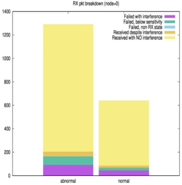
As depicted in Fig.4, the number of packets received by the PDA at the radio layer during a beacon period differs to a certain extent from the normal activity. For instance, the normal average number of packets received without interference is equal to 554 compared with 1086 in case of intrusion. The corresponding Radio Coefficient value is equal to 2.01, which is far beyond what would normally be expected ( that is in our case of study a value comprises between 0.5 and 1).
The Radio Coefficient value absolutely indicates the existence of abnormal behavior that requires more verification to deduce the intruders and take further preventions. Based on the results being found, the attack main purpose is to alter or send faulty data rather than damaging data packets via interference or collision, In fact, the number of packets encountering failure of transmission is equal to 92 (abnormal value) compared with 46 (normal value), this difference is way lower than the one representing the average number of received packets which only proves the aforementioned assumption. Fig. 5 represents the average energy consumed (in mw) when both abnormal and normal activities are taking place. The normal average energy consumption of biosensors during the active period of the beacon superframe is equal to 0.061 mw. However, the occurrence of the intrusion reduces considerably the energy consumption as it reaches a minimum value equals to 0.02138
mw for biosensor 1.
The priority that was given to sensor nodes to access the channel is correlated with the biosensor identifier, besides, the more the transceiver stays on for an exponential period of time the more it consumes a great amount of energy. In fact, the biosensor 1 has the highest priority to access the channel, which utterly reduces the duty cycle of the transceiver as it goes back to sleep state for the rest of the superframe active period, after completion of data packets transmission.
Fig. 4. The average packets Received at the radio module by the PDA
The biosensors 2, 3, 4 and 5 have to wait for the channel to be idle to proceed with the transmission. However, even though the transmission has been performed by the biosensors, the energy consumed is still lower that the normal average when the average number of received packets is much higher. The former only proves that intruders are gaining access to the channel to transmit faulty data packets, which explains the amount of energy consumed since the access to channel is shared with intruders with possibly the same identifier and priority. The energy consumed by the transceiver varies in respect to the type of biosensors, as a matter of fact, the energy consumption of biosensors respects a particular model[?], however, it is still a theoretical representation and does not give accurate values of batteries lifetime.
Fig. 5. The average energy consumption of biosensors
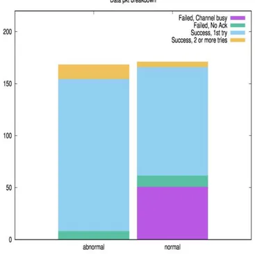
Fig. 6. The average Data reception packets of biosensors
successful transmission on the first or the second try indicates a successful reception of data packets by the end point i.e. the PDA, which is followed by a successful reception of the ac-knowledgement packets by the biosensors. All biosensors with the same destination address will be receiving and forwarding packets towards the upper layers, which explains the results being found.
The average end-To-end delay of data packets received
Fig. 7. Application latency of biosensors
at the application layer varies considerably as the number of packets transmitted increases. The latency goes hand in hand with the average reception of data packets. The more packets are received during different phases of the active superframe period, the more diverse is the interval of packets reception. When it comes to normal behavior, most of data packets are received with a maximum delay equals to 160ms whilst the equivalent end to end delay in case of abnormal activity is equal to 260ms. Even though packets are received with such important latency it is still represent a good indicator as the size of the buffer is fixed, therefore, packets may be stored for an additional amount of time until it regains access to the channel.
V. CONCLUSION
REFERENCES
[1] C. Li, A survey on routing protocols for large-scale wireless sensor networks. Sensors, 2011.
[2] X. Liu, A survey on clustering routing protocols in wireless sensor networks. Sensors, 2012.
[3] C. Henry, A survey on temperature-aware routing protocols in wireless body sensor networks. Sensors, 2013.
[4] A. Boulis, Impact of Wireless Channel Temporal Variation on MAC Design for Body Area Networks. ACM Transactions on Embedded Computing Systems, Vol.11, No.S2, 2012.
[5] M. M. Alam, Surveying Wearable Human Assistive Technology for Life and Safety Critical Applications: Standards, Challenges and Opportuni-ties. Sensors,14(5), 2014.
[6] J. Olivo, S. Carrara and al., Energy Harvesting and Remote Powering for Implantable Biosensors. IEEE SENSORS JOURNAL, VOL. 11, NO. 7, 2011.
[7] S. Lee, M. Annavaram, ”Wireless Body Area Networks: Where Does En-ergy Go?. IEEE International Symposium on Workload Characterization (IISWC), Date 4-6 Nov, 2012.
[8] K. S. Kwak, S. Ullah,An Overview of IEEE 802.15.6 Standard. 3rd International Symposium on Applied Sciences in Biomedical and Com-munication Technologies (ISABEL), 2010.
[9] D. Pediaditakis, Y. Tselishchev, A. Boulis, Performance and scalabil-ity evaluation of the castalia wireless sensor network simulator. 3rd International ICST Conference on Simulation Tools and Techniques, p. 53. ICST (Institute for Computer Sciences, Social-Informatics and Telecommunications Engineering), 2010.