Temperature Control System Using Fuzzy Logic
Technique
Isizoh A. N.
1, Okide S. O
2, Anazia A.E.
3. Ogu C.D.
41, 4: Dept. of Electronic and Computer Engineering, Nnamdi Azikiwe University, Awka, Nigeria. 2: Dept. of Computer Science, Nnamdi Azikiwe University, Awka, Nigeria.
3: Dept. of Electrical Engineering, Nnamdi Azikiwe University, Awka, Nigeria.
Abstract—Fuzzy logic technique is an innovative technology used in designing solutions for multi-parameter and non-linear control models for the definition of a control strategy. As a result, it delivers solutions faster than the conventional control design techniques. This paper thus presents a fuzzy logic based-temperature control system, which consists of a microcontroller, temperature sensor, and operational amplifier, Analogue to Digital Converter, display interface circuit and output interface circuit. It contains a design approach that uses fuzzy logic technique to achieve a controlled temperature output function.
Keywords- Fuzzy logic; microcontroller; temperature sensor; Analogue to Digital Converter (ADC).
I. INTRODUCTION
Human brain has an imprecise way of reasoning and thus has a high adaptive control approach. It does not reason as computers do. Computers reason in a clear statement that uses true or false (0 or 1) - an element is either a number of a given set or it is not.
There are many complex systems which do not fit into the precise categories of conventional set theory. This is because of the fact that there is no way to define a precise threshold to represent their complex boundary, and as such their control system is complex. Fuzzy logic was developed owing to this imprecise nature of solving control problems by computer. In a fuzzy logic-based system, a variable can take any truth value from a close set [0, 1] of real numbers thus generalizing Boolean truth values [1]. But the fuzzy facts are true only to some degrees between 0 and 1, and they are false to some degrees. Human brains work with fuzzy patterns. But computers cannot do so because its logic is based on approximate reasoning in a more familiar Boolean forms of logic used in conventional set theory. Fuzzy logic allows the
use of labels like “slightly”, “moderately”, medium, and “very” so that statements may be made with varying degree of precision. This flexibility is useful in coping with the imprecision of real-world situations such as designing precision environmental control systems.
In a broad sense, fuzzy logic refers to fuzzy sets - a set with non-sharp boundaries.
Fuzzy logic is widely used in machine controls, as it allows for a generalization of conventional logic and provides for
terms between “true” and “false”, like “almost true” or
“partially false”. This makes the logic not to be directly processed on computers but must be emulated by special codes.
A fuzzy logic based design control system offers flexibility in system design and implementation, since its implementation
uses “if then” logic instead of sophisticated differential
equations. Its technology provides room for graphical user interface, which makes it understandable by people who do not have process control backgrounds. Another key significance of a fuzzy logic-based control design is the ability to automatically and smoothly adjust the priorities of a number of controlled variables [2]. Finally, it helps to achieve a process that is stable for a long period of time without a need for intervention.
However, because of the rule-based operation of fuzzy systems, any reasonable number of inputs can be processed and numerous outputs generated; although defining the rule-base quickly becomes complex if too many inputs and outputs are choosen for a single implementation, since rules defining their interelations must also be defined.
There are countless applications of fuzzy logic. In fact many researchers still claim that fuzzy logic is an encompassing theory over all types of logic [3].
Fuzzy logic can control non-linear systems that would be difficult or impossible to model mathematically. This opens door for control system that would normally be deemed unfeasible for automation.
There are many approaches to implement fuzzy logic systems; they can be software only, hardware only or the combination of software and hardware. In recent years, fuzzy logic has been implemented using several technologies to solve real world problems such as image processing, robotics/motion control, pattern recognition, fuzzy database and industrial engineering applications. Fuzzy logic is also spreading applications in the field of telecommunications, particularly in broad band integrated networks, based on ATM Technology [4].
II. ANALYSIS
In this paper, microcontroller was used to implement a fuzzy logic-based temperature control system.
Microcontroller has to make decisions based on external temperature condition. The variable “temperature” which is inputted on the system can be divided into a range of states
such as “Cold”, “Cool”, “Moderate”, “Warm”, “Hot”, “Very hot”. Defining the bounds of these states is a bit tricky.
An arbitrary threshold might be used to separate “warm”
from “hot”, but this would result in a discontinuous change
when the input value passes over that threshold. The way to
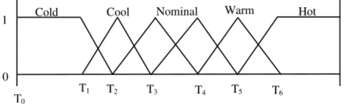
make the states “fuzzy” is to allow them change gradually from one state to the next. The input temperature states can be defined using “membership functions” as in figure 1.
Fig. 1: Temperature input membership function
With this scheme, the input variable state no longer jumps abruptly from one state to the next. Instead as the temperature changes, it loses value in one membership function while gaining value in the next.
The input variables in a fuzzy control system are mapped by sets of membership functions, known as “fuzzy sets”. The process of connecting a crisp input value to a fuzzy value is called fuzzification. A fuzzy-based control system can also incorporate the analog inputs of 0, 1 into its fuzzy functions that are either one value or another [5].
Given “mappings” of inputs variable into membership
functions and truth values, the microcontroller then makes decision of what action to take based on a set of “rules” for each of the form. For instance, if the external temperature is warm, then the fan speed is not very fast, but heater is low. In this example, the input variable temperature has values defined by fuzzy set. The output variables which are the speed of fan and heater temperature are also defined by a fuzzy set that can take values like “static”, “slightly increased”, “slightly
decreased”, and so on.
The considerations to make are that:
1) All the rules that apply are invoked using membership
functions and truth values obtained from the input to determine the result of the rule.
2) This result in turn will be mapped into a membership
function and truth value controlling the output variable.
3) These results are combined to give a specific (crisp)
answer ie. the actual room temperature through a procedure known as defuzzification.
III. FUZZY-BASED PROCESS USING “IF –THEN” STATEMENT/RULE
Fuzzy-based control process consists of an input stage, processing stage and an output stage. The input stage maps sensor or other inputs such as switches, thumbwheels and so on, to an appropriate rule and generates a result for each. The
processing stage then combines the results of the rules; and finally the output stage converts the combined result back to a specific control output value.
The processing stage is based on a collection of logic rules in the form of If-Then statements, where the IF part is called
the “antecedent” and the THEN part is called the “consequent”.
Typical fuzzy control systems have dozens of rules [6].
Consider a rule for a thermostat, IF (temperature is “cold”)
Then (heater is “high”).
This rule uses the truth value of the “temperature” input
which has truth value of “cold” to generate a result in a fuzzy
set for the “heater” output, which has truth value of “high”. This result is used with the results of other rules to finally generate the crisp composite output. Obviously, the greater the
truth value of “cold”, the higher the truth value of “high”,
though this does not necessarily mean that the output itself will
be set to “high” since this is only one rule among many. In some cases the membership functions can be modified
by “hedges” using “about”, “near”, “close to”,
“approximately”, “very”, “slightly”, “too”, “extremely” and
“somewhat”. The operations of these may have precise definitions, though the definitions can vary considerably between different implementations.
IV. FUZZY LOGIC VERSES CONVENTIONAL CONTROL METHODS
Fuzzy logic incorporates a simple rule-based IF X and Y Then Z approach to solve a control problem. The fuzzy logic model is empirically-based, relying on operational experience rather than technical understanding of the system. For example, rather than dealing with temperature control in terms such as
“Temp < 1000F” or 210C < Temp < 220C”; terms like “IF (process is too cool) AND (process is getting colder) THEN
(add heat to the process)” or “IF (process is too hot) AND
(process is heating rapidly) THEN (cool the process quickly)”
are used. These terms are imprecise and yet very descriptive of what must actually happen.
V. MICROCONTROLLER-BASED FUZZY LOGIC A microcontroller-based fuzzy logic control system has a fuzzy inference kernel and a knowledge-base. The fuzzy inference kernel is executed periodically to determine system output based on current system input. The knowledge-base contains membership functions and rules.
A programmer who does not know how the application system works can write a fuzzy inference kernel. One
“execution pass” through a fuzzy inference kernel generates system output signals in response to current system input conditions [7].
Fuzzification: The current input values are compared against stored input membership functions, usually in a program loop structure to determine the degree to which each linguistic variable of each system is true.
Rule Evaluation: Processes a list of rules from the knowledge-based using current fuzzy input values to produce a list of fuzzy output linguistic variable.
T1 T2 T3 T4 T5 T6 Hot Cold Cool Nominal Warm
1
0
Fig. 2: Block Representation of a Knowledge-Base and Inference Engine
Fuzzy Output: Considers raw suggestions for what the system output should be in response to the current input conditions.
Defuzzification: Dissolves multiple degree ambiguous by putting raw fuzzy outputs into a composite numerical output.
VI. STRUCTURED ANALYSIS AND DESIGN METHOD Problem statements were formulated after attempting to provide answers to problems noticed in the existing physical/logic system:
1) How can non-linear system that is difficult to model
mathematically be implored or implemented on control system like temperature control?
2) What kind of control system would be relatively
inexpensive and imprecise thus keeping the overall system cost and complexity low?
3) Can a control system inputs be easily altered or
modified to improve system performance?
The problem statements can now be answered using fuzzy logic-based computer control system, which should have the following features:
a) Ability to maintain the temperature of a room
automatically with the aid of devices like sensor, ADC, microcontroller, etc.
b) Ability to achieve the maintenance of a room
temperature by applying imprecise logic (fuzzy logic), where users define rules governing the target control system.
c) Flexibility in implementing multiple input variables
and achieving a smooth control function output.
The proposed logical/physical system with the problem statement and the features of the new system (a fuzzy logic-based temperature control system) seems to meet the requirement of the new system.
The system inputs are variable inputs introduced into the system with the aid of sensors (temperature sensors). These sensors deliver signals to the ADC. The ADC circuit converts analogue signals to digital signal which the microcontroller understands. The microcontroller is the heart of the system. It contains the inference kernel and the knowledge-base. The
fuzzy inference kernel is executed periodically to determine system outputs based on current system inputs. The knowledge-base contains membership functions and rules. The inference kernel is the engine of the microcontroller where fuzzification, rule evaluation and deffuzzification are done The display fuzzy output is done by the display unit, while the fuzzy output interface aids in the transmission of deffuzified signals to the system output [8].
VII. INPUT SOFTWARE DESIGN (FUZZIFICATION) This input software design is the design of the fuzzification process. This has to do with creating my fuzzy sets for each fuzzy state. These sets are shown in table 1.
TABLE 1:GENERATION OF THE FUZZY INPUT SETS
S /N
Fuzzy Sets (Representing Temperature ranges in oC.)
Fuzzy State
1 Fuzzy set 1:{0,1, 2,3,…,10oC} Very
Cold
2 Fuzzy set 2:{11,12,13,…,21oC} Cold
3 Fuzzy set 3: {22,23,24,…,32oC} Warm
4 Fuzzy set 4:{33,34, 35,…,43oC} Hot
5 Fuzzy set 5:{44,45,46,…,100oC} Very Hot
The table above represents the generation of fuzzy input sets. Each of these sets is converted to its digital equivalent and coded into the Microcontroller. The microcontroller, through the comparator and ADC then checks whatever that is coming out from the temperature sensor, with the already defined boundaries and thus carries out the required fuzzy operation. The temperature range of the monitored chamber determines what instruction the controller will give to the output interface devices. Each fuzzy output is determined by the fuzzy set within which the observed temperature falls into.
VIII. OUTPUT SOFTWARE DESIGN (DEFUZZIFICATION)/ DISPLAY OUTPUT DESIGN
The defuzzification process has to do with decoding of the output of the fuzzy decision done by the microcontroller based
Fuzzification
Fuzzy Inputs
Rule Evaluations
Fuzzy Outputs
Deffuzzification Rule List
F
u
zz
y
I
n
fe
re
n
ce
K
er
n
el
K
n
o
w
le
d
g
e
B
ase
Output Membership Function Input Membership Functions
System Inputs
Fig. 3: A Block Diagram of a temperature control system using fuzzy Logic
on the fuzzy input sets and the fuzzy control algorithm. Here, for each of the fuzzy sets, there is a display of the corresponding temperature and the fuzzy state, which will simultaneously carry out the expected fuzzy output action in the monitored chamber. The output of the microcontroller is relayed to the final output devices through the output interface devices. The final fuzzy output devices are the AC fan which serves as the cooler and AC heater. For the final fuzzy output, to increase the temperature of the monitored chamber for instance, the controller will have to increase the voltage of the heater and vice versa. The same applies to reducing the temperature of the monitored chamber. Table 2 shows the results of the fuzzy decision carried out by the microcontroller and what actually takes place at the final output devices for each of the specified fuzzy states.
TABLE 2:FUZZY DECISION BY THE CONTROLLER AND ITS EFFECT ON THE
FINAL OUTPUT DEVICES.
S /N
Heater Voltage in (V a.c)
Cooler Voltage in (V a.c)
Fuzzy State
1 220V 90V Very Cold
2 180V 130V Cold
3 150V 150V Warm
4 130V 180V Hot
5 90V 220V Very Hot
THE PSEUDOCODE Start
Initialize all memory locations to their starting values Display (Fuzzy logic Design by Isizoh A. N.)
Fetch temperature from ADC and compare with FUZZY SETs If temperature falls within FUZZY SET1 then
Display the fuzzy state (Very Cold) on the LCD Call the Control Algorithm for fuzzy control to the monitored chamber
(Very Cold1)
Elseif temperature falls within FUZZY SET2 then Display the fuzzy state (Cold) on the LCD
Call the Control Algorithm for fuzzy control to the monitored chamber
(Cold1)
Elseif temperature falls within FUZZY SET3 then Display the fuzzy state (Warm) on the LCD
Call the Control Algorithm for fuzzy control to the monitored chamber
(Warm1)
Elseif temperature falls within FUZZY SET4 then Display the fuzzy state (Hot) on the LCD
Call the Control Algorithm for fuzzy control to the monitored chamber
(Hot1)
Elseif temperature falls within FUZZY SET5 then Display the fuzzy state (Very Hot) on the LCD Call the Control Algorithm for fuzzy control to the monitored chamber
(Very Hot1) Endif
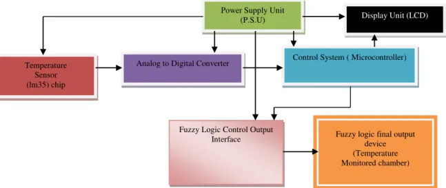
THE BLOCK DIAGRAM
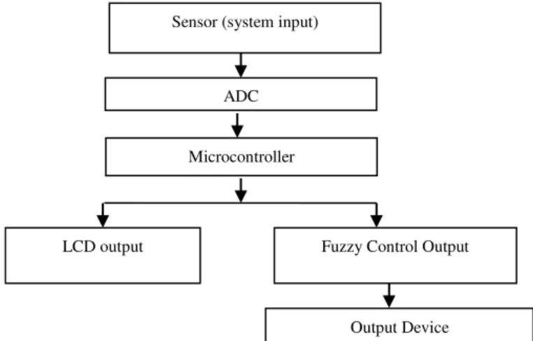
The system block diagram is made up of the following block items: the power supply unit, the temperature sensor, the Analog to digital converter (ADC), the control system (consisting a microcontroller), the display unit, the fuzzy control output interface and fuzzy output (consisting of the fan serving as the cooler and the heater). These subsystems are integrated together to generate the final system. Figure 4 shows the block diagram.
IX. CONCLUSION
The development of a fuzzy logic control system is a way forward to the improvement of industrial automation. This area of control will also improve and advance the study of control engineering in modern systems.
Sensor (system input)
ADC
Microcontroller
Fuzzy Control Output LCD output
REFERENCES
[1] Okorie F.C, “Fuzzy Logic Systems”, Jet Publishers Ltd, Lagos, 2008. [2] Willam C.P, Fuzzy Logic and Real Time Applications”, New Generation
Publishers, Ibadan, Nigeria, 2009.
[3] Lewis A.P., “Optimal Fuzzy Logic Control Technique”, Whitecap Publishing Co., Lagos, Nigeria, 2009.
[4] Francis T.C., “Solutions to Fuzzy Logic Controls”, Septon M. Publishers, London, 2010.
[5] Douglas V.H., “Microcontrollers and Interfacing: Programming
Hardware” McGraw Hill Inc, New York, 2008.
[6] Schuster A., “Microcontroller Principles and Applications”, Maxon Press Ltd, Rochester, 2008.
[7] Peters Andrew, “Real Time Controls”, Jones Communications, Ikeja, Lagos Nigeria, 2008.
[8] Dogan Ibrahim, “Microcontroller-Based Temperature Monitoring and
Control”, Elsevier Science & Technology Book, Maryland, USA, 2002.
Power Supply Unit (P.S.U)
Control System ( Microcontroller) Display Unit (LCD)
Analog to Digital Converter Temperature
Sensor (lm35) chip
Fuzzy Logic Control Output
Interface Fuzzy logic final output device (Temperature Monitored chamber)