www.mech-sci.net/7/247/2016/ doi:10.5194/ms-7-247-2016
© Author(s) 2016. CC Attribution 3.0 License.
A structure design method for compliant parallel
manipulators with actuation isolation
Guangbo Hao1and Xianwen Kong2
1School of Engineering, University College Cork, Cork, Ireland
2School of Engineering and Physical Sciences, Heriot-Watt University, Edinburgh, EH14 4AS, UK
Correspondence to:Guangbo Hao ([email protected])
Received: 9 June 2016 – Revised: 26 October 2016 – Accepted: 27 October 2016 – Published: 30 November 2016
Abstract. Since precise linear actuators of a compliant parallel manipulator suffer from their inability to tolerate the transverse motion/load in the multi-axis motion, actuation isolation should be considered in the compliant manipulator design to eliminate the transverse motion at the point of actuation. This paper presents an effective design method for constructing compliant parallel manipulators with actuation isolation, by adding the same number of actuation legs as the number of the DOF (degree of freedom) of the original mechanism. The method is demonstrated by two design case studies, one of which is quantitatively studied by analytical modelling. The modelling results confirm possible inherent issues of the proposed structure design method such as increased primary stiffness, introduced extra parasitic motions and cross-axis coupling motions.
1 Introduction
Compliant/flexure parallel manipulators (CPMs) have expe-rienced rapid development over the two past decades due to their merits of eliminated backlash, friction, wear and lubri-cation as well as a reduced number of parts, which are very suitable for applications in precision engineering (macro scale) and MEMS (micro scale) (Smith, 2003; Howell et al., 2013). When high-precision motion is required, contact lin-ear actuators such as piezoelectric (PZT) (Yue et al., 2010) and voice coil (VC) (Hiemstra et al., 2012) are the options because of their excellent positioning performances. How-ever, these linear actuators conventionally suffer from their inability to tolerate the transverse motions/loads in the multi-axis motion requirements. Therefore, actuation isolation that is defined as eliminating the transverse motion at the point of actuation (Awtar and Slocum, 2007) should be considered in the CPM design. In compliant mechanisms, completely eliminating the transverse motion and allowing the actuation point to perfectly move along the actuation direction is im-possible due to the nature of elasticity. Therefore, we aim to minimise the transverse motions of the linear actuator in the multi-axis motion system, by using a kind of decoupling mechanism that can transmit actuation force with negligible motion loss and can accommodate/absorb transverse motions
without producing transverse loads to the actuator (Awtar and Slocum, 2007).
There are a few successful methods to design CPMs, which include constraint-based method (Hale, 1999), FACT (Hopkins and Culpepper, 2010), and screw-theory-based method (Su et al., 2009). Those approaches mainly focus on design compliantparallelmechanisms/modules without considering actuation isolation. It is noteworthy to mention that great advances have been made in the conceptual de-sign (type synthesis or structure synthesis) of rigid-link par-allel mechanisms (see Kong and Gosselin, 2007 for example) since late 1990. The conceptual design of CPMs is closely-related to that of rigid-link parallel mechanisms. Even though several CPMs with actuation isolation have been proposed (Awtar et al., 2012; Hopkins and McCalib, 2012), the ap-proaches are limited to special-DOF/-DOC or complex to use by engineers. Here and throughout this paper DOF and DOC stand for degree of freedom and degree of constraint, respec-tively.
ap-proach by adding actuation legs. Case studies using the pro-posed method to design two CPMs with actuation isolation are discussed in Sect. 3. Analytical modelling is implemented in Sect. 4 to show the quantitative characteristic analysis of one resulting CPM. Section 5 draws the conclusions.
2 Constraint-based design approach
The design approach for actuation isolation in this section is a constraint-based design method, which is based on the following rule of rigid-link or compliant parallel mechanisms (see Kong and Gosselin, 2007 for instance):
Design rule: the addition of any number of 6-DOF legs to an original n-DOF (mostly parallel) mechanism results in a parallel mechanism with the same number of DOF and more legs.
The detailed procedure to design a CPM with actuation isolation is given below:
1. Design ann-DOF compliant mechanism without actu-ation isolactu-ation as the original mechanism using exist-ing methods such as those in Hale (1999), Hopkins and Culpepper (2010) and Su et al. (2009);
2. Design the same number of extra compliant legs as the number of DOF specified in Step 1, where each leg is a simple 6-DOF serial mechanism that consists of a 1-DOF translational (or prismatic) joint and a 5-DOF straight wire beam with its axis along with the direction of the translational joint.
3. Connect the wire beam in each extra leg to the motion stage of the original mechanism to comply with the fol-lowing conditions for arranging each leg:
a. the connection point between the wire beam in one extra leg and the motion stage should be able to be actuated by the linear actuator guided by the trans-lational joint; and
b. nadded extra legs working together should be able to effectively control the n-DOF of the original compliant mechanism by actuating the translational joint in each extra leg. This condition is the same as the validity condition of a set ofnactuated joints for ann-DOF rigid-link parallel mechanism (Kong and Gosselin, 2007).
4. Appropriately arrange the configuration according to specific requirements.
Note that the wire beam (or other alternative design) in each extra leg offers the decoupling of the transverse motions on the actuation (Awtar et al., 2012; Hopkins et al., 2012) where the actuator is guided by a translational joint. The length of the wire beam in each added leg can be adjusted for spe-cific reasons such as reducing the number of the DOF of the
actuation leg; and the translational joint can have different forms even though with amplification or direction-changing mechanisms. The above constraint-based design method can be seen as an “actuation-leg addition” method, which can be used to design any-DOF CPMs that are dominated by the original compliant mechanisms.
3 3-DOF CPM design cases
This section designs two 3-DOF CPMs for demonstrating the proposed actuation leg addition method: one is the in-plane 3-DOF 2T1R (T: translational; R: rotational) CPM (Fig. 1), and the other is the out-of-plane 3-DOF 2T1R CPM (Fig. 2).
3.1 In-plane 3-DOF CPM with actuation isolation The design of the in-plane 3-DOF CPM starts from design-ing an original in-plane 3-DOF compliant mechanism with-out considering actuation isolation (Fig. 1a). This original planar mechanism consists of 4 identical parallel wire beams with no intersection point (intersection at infinitely far po-sition), which can be designed using the emerging method (Hopkins and Culpepper, 2010; Su et al., 2009). By adding three extra 6-DOF legs (Fig. 1b) where the guiding transla-tional joint is a leaf-type parallelogram mechanism, an in-plane 3-DOF CPM with actuation isolation is obtained as shown in Fig. 1c. The FEA (finite element analysis) motion demonstrations are illustrated in Fig. 1d–f, which show three individual motions in the DOF directions.
3.2 Out-of-plane 3-DOF CPM with actuation isolation Designing the out-of-plane 3-DOF CPM also starts from de-signing an original out-of-plane 3-DOF mechanism with-out taking actuation isolation into account (Fig. 2a). This original out-of-plane mechanism is a symmetrical design for better performances. It is composed of 6 identical parallel wire beams in the same plane with more than one intersec-tion points, where the distance between any two intersecintersec-tion points are large enough. This original mechanism was re-ported in Hao (2016), which can actually be seen as a type of well-known 6-DOF Gough-Stewart platform at its planar actuation singularity position. By adding three extra 6-DOF legs (Fig. 1b), an out-of-plane 3-DOF CPM with actuation isolation is obtained as shown in Fig. 2b. The FEA motion demonstrations are illustrated in Fig. 2c and d.
4 Theoretical modelling and analysis
Figure 1.Design of an in-plane 3-DOF 2R1T CPM with actuation isolation.
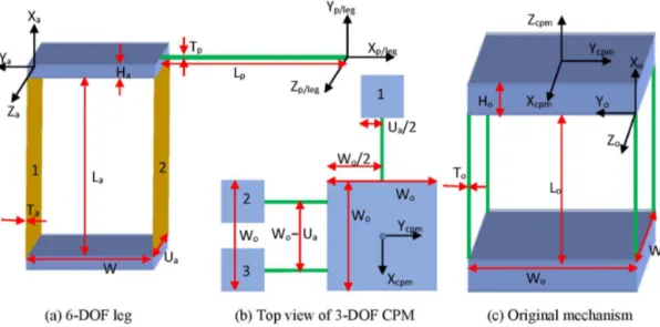
Figure 3.Geometry and coordinate system representations.
compared to its original mechanism, analytical modelling and compliance analysis with regard to the output motion stage can be carried out (Hao, 2016; Hao and Kong, 2013). It should be clarified that the motion range consideration of the modelled example based on the strength theory is out of scope of this paper.
We take the design in Fig. 1 with a specific legs’ arrange-ment as an example for comprehensive analysis in this sec-tion, whose all geometry and coordinate system representa-tions are clearly detailed in Fig. 3. All beams are assumed to have the same Young’s modules (E) and the shear modu-lus (G) with uniform cross sections. Three extra legs are also identical. For simplifying expressions, we normalise geomet-rical dimensions by the original mechanism’s characteristic lengthLo, and normalise the force byEIo/L2o, and moment
byEIo/Lo. Here,Io=To4/12, which is the second moment
of inertia of square cross-section areas of identical beams in the original mechanism.
The stiffness matrix for the original mechanism with re-gard to the centre of the motion stage is to be developed at first based on the work in Hao and Kong (2013). The stiff-ness matrix of each wire beam with square cross sections in Fig. 3c is expressed as
Kob=
12/(To/Lo)2 0 0 0 0 0
0 12 0 0 0 −6
0 0 12 0 6 0
0 0 0 1.69G/E 0 0
0 0 6 0 4 0
0 −6 0 0 0 4
(1)
where Kob is with regard to the local coordinate system
XoiYoi Zoi located at the centre of the mobile end of a wire
beam. All geometrical parameters are explained in Fig. 3c. The normalised torsional stiffness (fourth row and fourth col-umn) is calculated by considering warping influence (ignor-ing warp(ignor-ing constraint) of a square cross section, where the
torsional moment of inertia (2.25To4/16) is no longer
dou-ble of the second moment of inertia of a square cross section (i.e., not equal to polar moment of inertia, 2To4/12) (Hao,
2016; Chen and Bai, 2016).
The stiffness matrix of the original mechanism can be then derived based on the rule of parallel systems as follows (Hao and Kong, 2013):
Ko= 4
X
i=1
(Toi)TKobToi (2a)
where Ko is with regard to the global coordinate system
XcpmYcpmZcpm located at the (top-surface) centre of the
motion stage of the original mechanism.Toi is the
transfor-mation matrix from the local coordinate systemXoiYoi Zoi
at the mobile-end centre of a wire beam to the global coordi-nate system, which is elaborated below:
Toi=
cos (βi) 0 sin (βi) 0 0 0
0 1 0 0 0 0
−sin (βi) 0 cos (βi) 0 0 0
0 0 0 cos (βi) 0 sin (βi)
0 0 0 0 1 0
0 0 0 −sin (βi) 0 cos (βi)
cos (γi) −sin (γi) 0 0 0 0
sin (γi) cos (γi) 0 0 0 0
0 0 1 0 0 0
0 0 0 cos (γi) −sin (γi) 0
0 0 0 sin (γi) cos (γi) 0
0 0 0 0 0 1
1 0 0 0 dzi −dyi
0 1 0 −dzi 0 dxi
0 0 1 dyi −dxi 0
0 0 0 1 0 0
0 0 0 0 1 0
0 0 0 0 0 1
In Toi,βi=π/2,γi=π,dzi= −Ho/Lo (i=1, 2, 3, or 4);
dx1=0.5Wo/Lo, dy1= −0.5Wo/Lo; dx2=0.5Wo/Lo,
dy2=0.5Wo/Lo; dx3= −0.5Wo/Lo, dy3=0.5Wo/Lo;
dx4= −0.5Wo/Lo,dy4= −0.5Wo/Lo.
The compliance matrix of the original mechanism can be produced as
Co=(Ko)−1. (3)
The stiffness matrix for the extra leg is modelled in the fol-lowing steps. Similar to Eq. (1), the 5-DOF wire beam with square cross sections in the extra leg (Fig. 3a) has its stiffness matrix with regard to its local coordinate systemXpYpZp:
Kpb= T2 p Lp/
Io L3 o
0 0 0 0 0
0 12Ip
L3 p
/Io L3 o
0 0 0 −6Ip
L2 p
/Io L2 o
0 0 12Ip
L3 p
/Io L3 o
0 6Ip
L2 p
/Io L2 o
0
0 0 0 1.69GIp
Lp/ EIo
Lo 0 0
0 0 6Ip
L2 p
/Io L2 o
0 4Ip
Lp /Io
Lo
0
0 −6Ip
L2 p
/Io L2 o
0 0 0 4Ip
Lp/ Io Lo (4)
whereIp=Tp4/12.
The stiffness matrix of a leaf beam in the 1-DOF transla-tional joint can be obtained as below:
Kab=
T2 a La
/Io L3 o
0 0 0 0 0
0 12Ia1
L3 a
/Io L3 o
0 0 0 −6Ia1
L2 a
/Io L2 o
0 0 12Ia2
L3 a
/Io L3 o
0 6Ia2
L2 a
/Io L2 o
0
0 0 0 GUaTa3
3La /
EIo Lo
0 0
0 0 6Ia2
L2 a
/Io L2 o
0 4Ia2
La/ Io
Lo 0
0 −6Ia1
L2 a
/Io L2 o
0 0 0 4Ia1
La /Io
Lo (5)
whereKab is the matrix with regard to the local coordinate
system XaiYai Zai located at the centre of the mobile end of a leaf beam.Ia1=UaTa3/12 andIa2=TaUa3/12. The
tor-sional stiffness for a rectangular cross section (Ua>10Ta) is
calculated by considering warping influence (ignoring warp-ing constraint) (Hao and Kong, 2013; Chen and Bai, 2016).
The stiffness matrix of the translational joint composed of two identical leaf beams can be derived as follows (Hao, 2016):
Ka= 2
X
i=1
(Tai)TKabTai (6a)
where Ka is derived with regard to the coordinate system
XpYpZp.Tai is the transformation matrix from the local
co-ordinate systemXaiYaiZaiat the mobile-end centre of a leaf
beam to the coordinate systemXpYpZp, which is detailed
below:
Tai=
cos (γi) −sin (γi) 0 0 0 0
sin (γi) cos (γi) 0 0 0 0
0 0 1 0 0 0
0 0 0 cos (γi) −sin (γi) 0
0 0 0 sin (γi) cos (γi) 0
0 0 0 0 0 1
1 0 0 0 dzi −dyi
0 1 0 −dzi 0 dxi
0 0 1 dyi −dxi 0
0 0 0 1 0 0
0 0 0 0 1 0
0 0 0 0 0 1
. (6b)
In Tai, γi= −π/2, dzi=0 (i=1 or 2); dx1= −(Wa +Lp)/Lo,dy1= −Ha/Lo;dx2= −Lp/Lo,dy2= −Ha/Lo.
Therefore, the compliance matrix of the extra leg can be derived based on the rule of serial systems (Hao and Kong, 2013) as:
Cleg=(Ka)−1+ Kpb −1
(7)
where the leg’s compliance matrixClegis based on the
coor-dinate systemXlegYlegZlegoverlapping with the local
coor-dinate systemXpYpZp.
Finally, the stiffness matrix, with regard to the global co-ordinate systemXcpmYcpmZcpm, of the resulting CPM with
actuation isolation is shown:
Kcpm= 3
X
i=1
TlegiT Cleg −1
Tlegi+Ko (8a)
whereTlegiis the transformation matrix from the leg’s
coor-dinate systemXlegi YlegiZlegi to the global coordinate
sys-temXcpmYcpmZcpm, which is explained below:
Tlegi=
1 0 0 0 0 0
0 cos (αi) −sin (αi) 0 0 0
0 sin (αi) cos (αi) 0 0 0
0 0 0 1 0 0
0 0 0 0 cos (αi) −sin (αi)
0 0 0 0 sin (αi) cos (αi)
cos (γi) −sin (γi) 0 0 0 0
sin (γi) cos (γi) 0 0 0 0
0 0 1 0 0 0
0 0 0 cos (γi) −sin (γi) 0
0 0 0 sin (γi) cos (γi) 0
0 0 0 0 0 1
1 0 0 0 dzi −dyi
0 1 0 −dzi 0 dxi
0 0 1 dyi −dxi 0
0 0 0 1 0 0
0 0 0 0 1 0
0 0 0 0 0 1
. (8b)
In Tlegi (i=1, 2 or 3): α1=α2=α3= −π/2;
γ1=0, γ2=γ3= −π/2; dx1= −0.5Wo/Lo,
dx2= −0.5(Wo−Ua)/Lo, dx3=0.5(Wo−Ua)/Lo;
dy1=0, dy2= −0.5Wo/Lo, dy3= −0.5Wo/Lo;
The compliance matrix of the CPM with actuation isola-tion can be thus obtained as
Ccpm= Kcpm −1
. (9)
LetLa=50 mm, Ta=0.75 mm,Wa=12 mm,Ha=10 mm,
Ua=12 mm; Tp=2 mm, Lp=50 mm; To=2 mm,
Lo=50 mm, Wo=50 mm, Ho=10 mm; E=69 000 MPa
andG=26 000 MPa, the linear compliance matrices for the original mechanism and the CPM with actuation isolation, respectively, are shown below:
Co=
2.09×10⁻²
0 0 0 9.33×10⁻⁵
0 0 2.09×10⁻²
0 −9.33×10⁻⁵
0 0
0 0 3.33×10⁻⁵ 0 0 0
0 −9.33×10⁻⁵ 0 1.33×10⁻⁴ 0 0
9.33×10⁻⁵
0 0 0 1.33×10⁻⁴
0
0 0 0 0 0 3.77×10⁻²
(10a)
Ccpm=
1.47×10⁻² −7.02×10⁻⁴ −4.53×10⁻⁷ 2.95×10⁻⁶ 6.38×10⁻⁵ −4.91×10⁻³ −7.02×10⁻⁴ 1.43×10⁻² −9.49×10⁻⁷ −6.06×10⁻⁵ −2.94×10⁻⁶ 2.56×10⁻³ −4.53×10⁻⁷ −9.49×10⁻⁷ 3.33×10⁻⁵ 9.89×10⁻⁸ −4.95×10⁻⁸ −7.34×10⁻⁹
2.95×10⁻⁶ −6.06×10⁻⁵ 9.89×10⁻⁸ 1.33×10⁻⁴ 1.22×10⁻⁸ −1.08×10⁻⁵
6.38×10⁻⁵ −2.94×10⁻⁶ −4.95×10⁻⁸ 1.22×10⁻⁸ 1.33×10⁻⁴ −2.06×10⁻⁵ −4.91×10⁻³ 2.56×10⁻³ −7.34×10⁻⁹ −1.08×10⁻⁵ −2.06×10⁻⁵ 1.79×10⁻²
. (10b)
Equations (10a) and (10b) both show the agreement that the diagonal compliance entries corresponding to the DOF direc-tions (primary compliance) are comparable, and are at least 100 times larger than other compliance entries corresponding to the DOC directions. This means that the added extra legs does not change the mobility of the original mechanism.
However, in comparison with the original mechanism the added legs with the current specific arrangement can result in two problems as below, exposing trade-offs to be considered:
1. The extra legs do increase the stiffness in the DOF direc-tions, which is reflected by the decreased primary com-pliances in Eq. (10b). For the analysis case study in this section, the primary compliances of the CPM with actu-ation isolactu-ation are reduced by 29.67 % in thexaxis, by 31.58 % in they axis, and by 52.52 % about thezaxis, respectively. However, there is no observation on the compliance/stiffness change of the motion stage in the DOC directions since the DOC stiffness of the original mechanisms is much larger (100 times larger) than the added stiffness in the same directions.
2. The added legs can cause issues associated with par-asitic motions (related to DOC) and cross-axis cou-pling (related to DOF) that do not exist in the orig-inal mechanism. For instance, the force, applied on the origin of the global coordinate system along the x axis, cannot only produce the primary translation along thexaxis (primary compliance 1.47×10⁻²), but also parasitic translation in thezaxis (parasitic compli-ance−4.53×10⁻⁷), parasitic rotation about thex axis (parasitic compliance 2.95×10⁻⁶), and cross-axis cou-pling motions along the y axis (coupling compliance −7.02×10⁻⁴) and about thezaxis (coupling compli-ance−4.91×10⁻³).
Note that the resulting CPM with actuation isolation has al-leviated existing parasitic rotation in they axis (orx axis)
caused by the force along thexaxis (oryaxis), with a reduc-tion of 31.62 % (or 35.05 %). Observing Eq. (10b), we can see that if the compliance entries below the order of 10−4
can be neglected due to the accuracy tolerance, all parasitic motions vanish while only cross-axis coupling compliance terms remain.
The above analytical modelling method can also be used to quantitatively analyse the stiffness/compliance of the pro-posed out-of-plane 3-DOF CPM with actuation isolation (Fig. 2), which is left for the future work. The modelling re-sults would be useful to identify if the added legs are able to actuate all DOF directions and/or if there exists decoupling between input and output. If each primary compliance in the compliance matrix of the resulting CPM includes the con-tribution of at least one of the actuation compliances of the translational joints in added legs, all DOF are actively con-trollable. It should be mentioned that a 6-DOF CPM with actuation isolation can be proposed using the method pre-sented in Sect. 2 where the original compliant mechanism is a 0-DOC (6-DOF) mechanism (free rigid body). The 6-DOF CPM is composed of six actuation legs, each of which seri-ally consists of a 1-DOF translational joint and a 5-DOF wire beam with its axis along with the direction of the translational joint. For practical reasons, the six wire beams are arranged in three pairs along three orthogonal directions (Hale, 1999).
5 Conclusions
An actuation-leg addition approach has been presented in this paper for the conceptual design of any-DOF CPMs with actu-ation isolactu-ation. The added leg is a 6-DOF serial chain, which is a very simple design in compliant mechanisms and can be arranged in different desired positions. This method pro-vides an universal/general solution to consider actuation iso-lation for any (compliant) parallel mechanisms. Two design studies have been implemented with one case analytically modelled. The linear modelling results quantitatively show that the added extra legs, although obtaining the actuation isolation, may cause several inherent problems including in-creased primary stiffness, introduced extra parasitic motions and cross-axis coupling motions.
It is hoped that the proposed method can be used as an initial solution for further comprehensive modelling and geometrical optimization of CPMs towards specific applications. Trade-offs should be carefully considered between the strength and weakness using actuation isolation. Further experimental verification is also to be investigated.
Edited by: K. Mianowski
Reviewed by: two anonymous referees
References
Awtar, S. and Slocum, A. H.: Constraint-based design of parallel kinematic XY flexure mechanisms, ASME J. Mech. Design, 129, 816–830, 2007.
Awtar, S., Ustick, J., and Sen, S.: An XYZ parallel kinematic flexure mechanism with geometrically decoupled degrees of freedom, ASME J. Mech. Robot., 5, 015001, doi:10.1115/1.4007768, 2012.
Chen, G. and Bai, R.: Modeling Large Spatial Deflections of Slender Bisymmetric Beams in Compliant Mechanisms Using Chained Spatial-Beam Constraint Model, J. Mech. Robot., 8, 041011, doi:10.1115/1.4032632, 2016.
Hale, L. C.:Principles and Techniques for Designing Precision Ma-chines, PhD thesis, Massachusetts Institute of Technology, Cam-bridge, MA, 1999.
Hao, G.: Determinate design and analytical analysis of a class of symmetrical flexure guiding mechanisms for linear actuators, J. Mech. Design, 139, 012301-1–012301-12, 2016.
Hao, G. and Kong, X.: A normalization-based approach to the mo-bility analysis of spatial compliant multi-beam modules, Mech. Mach. Theory, 59, 1–19, 2013.
Hiemstra, D. B., Parmar, G., and Awtar, S.: Performance tradeoffs posed by moving magnet actuators in flexure-based nanoposi-tioning, ASME/IEEE T. Mechatron., 99, 1–12, 2012.
Hopkins, J. B. and Culpepper, M. L.:, Synthesis of multi-degree of freedom, parallel flexure system concepts via freedom and con-straint topology (FACT) – Part I: Principles, Precis. Eng., 34, 259–270, 2010.
Hopkins, J. B. and McCalib, D. B.: Synthesizing precision flex-ures that decouple displacement-based actuators, in: 27th Annual Meeting of the American Society for Precision Engineering, 21– 26 October 2012, San Diego, CA, 2012.
Howell, L. L., Magleby, S. P., and Olsen, B. M.: Handbook of Com-pliant Mechanisms, Wiley, New York, 2013.
Kong, X. and Gosselin, M.: Type Synthesis of Parallel Mechanisms, Springer-Verlag, Berlin, 2007.
Smith, S. T.: Flexures: Elements of Elastic Mechanisms, Taylor and Francis, London, 2003.
Su, H. J., Denis, V. D., and Judy, M. V.: A screw theory ap-proach for the conceptual design of flexible joints for com-pliant mechanisms, ASME J. Mech. ’ Robot., 1, 041009, doi:10.1115/1.3211024, 2009.