Vol. 10, December 2012 826
Design of a Composite Drive Shaft and its Coupling for Automotive
Application
M.R. Khoshravan, A. Paykani*
Department of Mechanical Engineering, Parand Branch, Islamic Azad University Parand, Iran
ABSTRACT
This paper presents a design method and a vibration analysis of a carbon/epoxy composite drive shaft. The design of the composite drive shaft is divided into two main sections: First, the design of the composite shaft and second, the design of its coupling. Some parameters such as critical speed, static torque, fiber orientation and adhesive joints were studied. Tsai-Hill failure criterion was implemented to control the rupture resistance of the composite shaft and then its critical speed analysis and modal analysis were carried out using ANSYS. The behavior of materials is considered nonlinear isotropic for adhesive, linear isotropic for metal and orthotropic for composite shaft. The results showed significant points about the appropriate design of composite drive shafts. The substitution of composite drive shaft has resulted in considerable weight reduction about 72% compared to conventional steel shaft. Furthermore, results revealed that the orientation of fibers had great influence on the dynamic characteristics of the composite shaft.
Keywords: Composite drive shaft; carbon/epoxy; design; modal analysis, natural frequency.
1. Introduction
Nowadays, composite materials are used in large volume in various engineering structures including spacecrafts, airplanes, automobiles, boats, sports' equipments, bridges and buildings. The widespread use of composite materials in industry is due to the excellent characteristics such as, specific strength and specific hardness or strength-weight ratio and hardness-weight ratio. The application of composite materials started first at the aerospace industry in 1970s, but nowadays after only three decades, it has been developed in most industries. Meanwhile, the automotive industry, considered as a pioneer in every country, has been benefited from theproperties and characteristics of these advanced materials. Along with progress in technology, metallic automotive parts have been replaced by composite ones. Power transmission drive shafts are used in many applications, including cooling towers, pumping sets, aerospace, structures, and automobiles. Drive shafts are usually made of solid or hollow tube of steel or aluminum [1]. For automotive applications, the first composite drive shaft was developed by the Spicer U-Joint division of Dana Corporation for Ford econoline van models in
Design of a Composite Drive Shaft and its Coupling for Automotive Application, M.R. Khoshravan / 826‐834
Journal of Applied Research and Technology 827 more than four times specific stiffness of steel or
aluminum materials, it is possible to manufacture composite drive shaft s in one-piece. The composite drive shaft has many benefits such as reduced weight and less noise and vibration [4].
(a)
(b)
Figure 1. Photographic view of: a) two-piece steel; b) one-piece composite drive shaft [5].
Numerous studies have been carried out to find out the optimal design and analysis of composite drive shafts with different materials and fibers orientation. Pollard [5] studied different applications of composite drive shafts for automotive industry. He compared the advantages and disadvantages of them at various conditions. Rastogi [6] implemented a FEA approach to design and analyze a composite drive shaft with its couplings in different conditions. Rangaswamy et al. [7] optimized and analyzed a one-piece composite drive shaft using genetic algorithm and ANSYS. They found that the use of composite materials lead to the significant reduction in weight compared to steel drive shaft. They also reported that the fiber orientation of a composite shaft strongly affects the buckling torque. Kumar [8] performed an optimum design and analyzed a composite drive shaft for automobile application using a genetic algorithm approach. He optimized
the design parameters with the objective of minimizing the weight of the composite drive shaft. Chowdhuri et al. [9] replaced a two-piece composite drive shaft by a one-piece steel shaft. They proposed two different designs consisting of graphite/epoxy and aluminum with graphite/epoxy. Abu Talib et al. [3] implemented a finite element analysis to design composite drive shafts incorporating carbon and glass fibers within an epoxy matrix. A configuration of one layer of carbon– epoxy and three layers of glass–epoxy was used. Their results showed that the buckling strength is the main concern over shear strength in the drive shaft design. Badie et al. [10] conducted a finite element analysis to study effects of design variables on the drive shaft critical mechanical characteristics and fatigue resistance. They found out that stacking sequence has an obvious effect on the fatigue resistance of the drive shaft.
An efficient design of composite drive shaft could be achieved by selecting the proper variables, which can be identified for safe structure against failure and to meet the performance requirements. Since the length and outer radius of drive shafts are limited due to spacing, the design variables include the inside radius, layers thickness, number of layers, fiber orientation angle and layers stacking sequence. In the optimal design of the drive shaft these variables are constrained by the lateral natural frequency, torsional vibration, torsional strength and torsional buckling. In the present work an effort has been made to design a HM-Carbon/Epoxy composite drive shaft. A one-piece composite drive shaft for rear wheel drive automotive application was designed and analyzed using ANSYS software.
2. Design of a composite drive shaft
Design of a Composite Drive Shaft and its Coupling for Automotive Application, M.R. Khoshravan / 826‐834
Vol. 10, December 2012 828
strength and a 90º angle is the best for buckling strength [10]. The main goal design is to achieve the minimum weight while adjusting the variables to meet a sufficient margin of safety, which is translated in a critical speed (natural frequency) higher than the operating speed (above 9200 rpm), a critical torque higher than the ultimate transmitted torque and a nominal stress (the maximum at fiber direction) less than the allowable stress after applying any of the failure criteria like the maximum stress criteria (for example Tsai-Hill criteria). Due to the physical geometry (larger radius) of the drive shafts used in the mentioned applications including automotive applications, the shear strength, which specifies the load carrying capacity,it is of minor design importance since the failure mode is dominated by buckling therefore the main design factors are the bending natural frequency and the torsional buckling strength, which are functions of the longitudinal and hoop bending stiffness, respectively [10].
The material properties of the drive shaft were analyzed with classical lamination theory (CLT). The variable of the laminate thickness has a big effect on the buckling strength and slight effect on bending natural frequency. From the properties of the composite materials, at given fiber angles, the reduced stiffness matrix can be constructed. The expressions of the reduced stiffness coefficients Qij
in terms of engineering constants are as follows [3]:
12 1 2 21 12 66 21 12 2 12 12 21 12 2 22 21 12 1 11 , 1 1 , 1 E E G Q E Q E Q E Q (1)
where E is the modulus of elasticity, G is the modulus of rigidity and is the Poisson’s ratio. The second step is to construct the extensional stiffness matrix [A]. This matrix is the summation of the products of the transformed reduced stiffness matrix [Q] of each layer and the thickness of this layer as [3]:
[ ] [ ] ( 1)
1
k k kN
k
z z Q
A (2)
The A matrix is in (Pa. m) and the thickness of each ply is calculated in reference to their coordinate location in the laminate. The A matrix is used to calculate Ex andEh, which are the average module in the axial and hoop directions, respectively from [3]:
] [ 1 ] [ 1 11 2 12 22 22 2 12 11 A A A t E A A A t E h x (3)
The HM-Carbon/Epoxy composite drive shaft was designed with the objective of minimizing the shaft weight which is subjected to the constraints such as torque transmission, torsional buckling strength capabilities and natural bending frequency.
2.1 Buckling torque
Since the drive shaft is long, thin and hollow, there is a possibility for it to buckle. The expression of the critical buckling torque for thin-walled orthotropic tube is given as [3],
2 / 3 4 / 1 3 2 ] )[ 272 . 0 )( 2 ( r t E E t r
Tcr x h (4)
Where r, is the mean radius and t is the total thickness. It is obvious that the stiffness modulus at hoop direction (
E
h) plays a big role in increasing the buckling resistance. The factor of safety is the ratio of the buckling torque to the ultimate torque.2.2 Lateral bending natural frequency
Design of a Composite Drive Shaft and its Coupling for Automotive Application, M.R. Khoshravan / 826‐834
Journal of Applied Research and Technology 829 Figure 2. The effect of shaft length on critical speed [5]
Critical speed of a shaft is obtained through the following equation:
(5)
Where Ncris the critical speed and f is the bending frequency. Considering that the natural frequency of a shaft according to the above equation is inversely proportional to the square of shaft's length and is proportional to the square root of Young's modulus, the conventional steel drive shafts are made of two pieces to increase the natural frequency of the shaft, which results in overall increase in the weight of the shaft. So, in order to increase the natural frequency, the length of shaft should be reduced or
E
/
ratio should be increased. Despite the space limitations that confines outer shaft diameter , the only way to increase the critical speed is to increase
/
E
ratio (specific modulus) [7].One of the interesting properties of metals is that although there is a clear difference in their density, their specific modulus is almost constant. By using fiber-reinforced composites, fiber orientation arrangement turns possible in the drive shaft; therefore, the bending modulus will be higher. Also their relative density is low resulting in the desirable specific modulus and an i increase in the critical speed [4]. The natural frequency of the drive shaft was obtained through Timoshenko theory as the following equation [8]:
2 2
2
30
2
nt s
p
Er
f
K
L
(6)where fntis the natural frequency, p is the first natural frequency and ,Eare properties of the steel shaft.
K
sis given by the following equation [8]:2 2 2
2 2
1
1 1
2
s
s
f E p r
K L G
(7)
where G is the modulus of rigidity of steel shaft and s
f
is equal to 2 for hollow cross sections. Then critical speed is obtained in the following way [7]:60
cr nt
N
f
(8)2.3 Load carrying capacity
The composite drive shaft was designed to carry the torque without failure. The torsional strength or the torque at which the shaft fails, is directly related to the laminate shear strength through
l m s
r
t
T
2
2
(9)where Tsis the failure torque, lis the in-plane shear strength of the laminate, rm is the mean radius and t is the thickness [3].
2.4 Tsai-Hill failure criterion
By using Tsai-Hill failure criterion, it would be possible to calculate the dimension for failure. With the thickness of 2.03 millimeters and the applied loads, the 0
0 fibers will not be ruptured. With the thickness of 2.2 millimeters and the applied loads, the 0
90 fibers will not be ruptured. Because of shaft´s torsion , the buckling is negligible [1].
(10)
2 2
2
2
EI
Ncr l A
EI f
mL
2 2 2
2 2
l t t l lt
lr tr lr ltr
Design of a Composite Drive Shaft and its Coupling for Automotive Application, M.R. Khoshravan / 826‐834
Vol. 10, December 2012 830
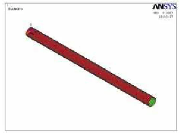
3. Modal analysis of composite drive shaft using ANSYS
In this study, a finite element analysis was conducted using ANSYS commercial software. The 3-D model was developed and a typical meshing was generated by using Shell 99 element. The drive shaft was fixed at both ends and it was subjected to torque in the middle. The torque transmission capability of the drive shaft was taken as 3000 N.m, the length and the outer diameter here were considered as 2 meters and 120 millimeters, respectively [1]. The shaft rotates at a constant speed about its longitudinal axis. The shaft has a uniform, circular cross section. The shaft was perfectly balanced, all damping and nonlinear effects were excluded. The stress-strain relationship for composite material is linear and elastic; hence, Hook’s law is applicable for composite materials. Since lamina is thin and no out-of-plane loads were applied, it was considered as under the plane stress. Since the fiber volume of 60% is the standard fiber volume fraction for most industries, it was selected for composite drive shaft [11]. Table 1 shows the mechanical properties of each layer of the laminate. Among the various laminate configurations, [±45] laminates possess the highest shear modulus and are the primary laminate type used in purely torsional applications [6]. To meet the minimum resonance frequency, the drive shaft must have an adequate axial modulus and since the axial modulus of a [±45] laminate is rather low, 00 layer had to be added to the lay-up to improve the resonance frequency [10]. Regarding the design correlations the appropriate fiber arrangement of the composite drive shaft was obtained as[900/00/4504].
Figure 3 illustrates the domain of a finite element mesh. Once the finite element mesh and the layers were created, the orientation of materials was defined for the shell element and the layer materials for each of these elements have been allocated. The other steps included placing the boundary conditions and selecting appropriate solvers. The drive shaft rotated at maximum speed so the design should include a critical frequency. If the drive shaft rotates at its natural frequency, it can be severely vibrated or even collapsed. The modal analysis was performed to find the natural frequencies in lateral directions.
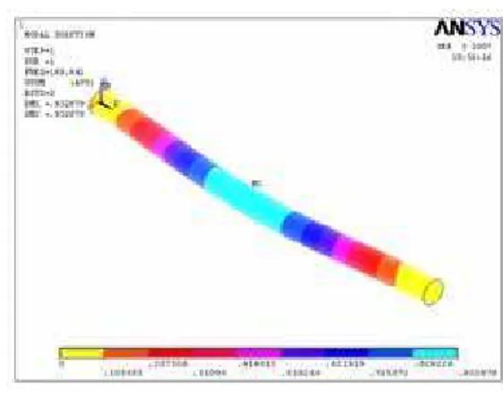
The mode shapes for all material combinations were obtained to their corresponding critical speeds. A number of fundamental modes, all of them critical frequencies, were obtained. The dynamic analysis shows that the first natural frequency is 169.64 Hz, and according to it the critical speed is equal to 10178 rpm, which is much more than the critical rotational speed of 4000 rpm. According to the equations obtained in the previous section, natural frequency of a specific composite drive shaft is 4570.2 rpm.This value is very different from the initial one because some assumptions have been used for obtaining natural frequency in Timoshenko theory [8].
Property HM carbon/epoxy )
(
11 Gpa
E 190
) (
22 Gpa
E 7.7
) (
12 Gpa
G 4.2
12
0.3) (
1 1
Mpa c
t
870) (
2 2
Mpa c
t
540)
(
12
Mpa
30) /
(kg m3
1600f
V
0.6Table 1. Mechanical properties for each Lamina of the laminate.
Figure 3. The mesh configuration of composite shaft.
Design of a Composite Drive Shaft and its Coupling for Automotive Application, M.R. Khoshravan / 826‐834
Journal of Applied Research and Technology 831 composite drive shaft in different directions at first
mode. The natural frequencies of composite drive shaft are given in Table 2.
Figure 4. The deformation form of composite shaft at first mode.
Figure 5. The displacement rate of composite shaft in x-direction at first mode.
Frequency number Frequency (Hz)
1 169.64
2 182.67
3 226.73 4 255.98 5 278.44
Table 2. Natural frequencies of composite drive shaft.
Figure 6. The total displacement contour of composite shaft at first mode.
3.1 Effect of fiber angle
The fibers orientation angle has a big effect on the natural frequency of the drive shaft. As we can se in figure 7, the fibers must be oriented at zero degree to increase the natural frequency by increasing the modulus of elasticity in the longitudinal direction of the shaft. The drive shaft loses 38% of its natural frequency when the carbon fibers oriented in the hoop direction at 90º instead of 0º. The cost factor plays a role in selecting only one layer of carbon/epoxy. The stacking sequence has no effect on the natural frequency since there is no load applied when defining the natural frequency.
Figure 7. The effect of changing the carbon fiber orientation angle in a drive shaft of stacking
] 45 / 0 / 90
[ 04
0
Design of a Composite Drive Shaft and its Coupling for Automotive Application, M.R. Khoshravan / 826‐834
Vol. 10, December 2012 832
3.2 Design of adhesive joints in composite drive shafts
The joints used for connecting composite materials can be metallic or non-metallic. Steel fasteners, due to the possibility of galvanic corrosion with carbon-epoxy materials, are mainly made of titanium or stainless steel. Other alloys such as aluminum or steel can be used provided that no contact with the surface willoccurre . Joints were divided into metal screws and rivets. Non-metallic connectors were created from reinforced thermo set or thermoplastic resins. By using this connection, structural weight reduces and corrosion problems disappear [12]. In this part, the thickness of the adhesive and the length of the adhesive bond were computed.
Then, a finite element analysis of this type of bond was performed using ANSYS software. The "Araldite" adhesive was used in this study. The following correlations were used to calculate the required parameters [1]:
max
2
tanh
2
m
c
c a
a
G l a
Gee
(11)
Where l is the length of adhesive bond. For obtaining reasonable results the only possible way is to increase the value of e. so the thickness of the adhesive and the length of the adhesive bond were obtained 12 millimeters and 4.5 centimeters, respectively. The details of the bond were given in table 3.
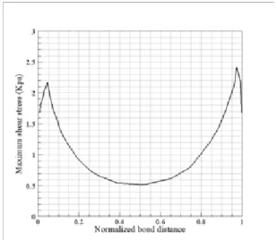
For analysis, a FE model was applied using the 3 - D linear solid elements. A suitable mesh for finite element modeling of adhesive layer was needed. The shear distribution stress of the adhesive was demonstrated in figure 8. The application of the appropriate adhesive, resulted in a decreased In the maximum shear stress in the adhesive at the edges of the connection; however, if the stresses remain the same in the middle connection, the start of failure will depend on the relative shear strength values within the adhesive [6].
Property Value
E
2.5 GpaG
1 Gpac
e
0.25l
45 mmLayers orientation
Table 3. Mechanical properties of the adhesive [12].
Figure 8. Shear stress distribution in the adhesive bond connection.
4. The weight comparison between composite and steel drive shafts
The entire vehicle drive shaft consists of several rotating masses. About 17-22% of the power generated by the engine was wasted due to rotating mass of power train system. Power was lost because a lot of energy was needed to rotate/ move heavy parts. This energy loss could be reduced by decreasing the amount of rotating mass. In figure 9, a mass comparison between steel and composite drive shafts has been done. The substitution of composite shaft has resulted in considerable weight reduction about 72% compared to conventional steel shaft. Due to an excessive weight reduction the geometry would become slender which would lead to a large deflection.
6
Design of a Composite Drive Shaft and its Coupling for Automotive Application, M.R. Khoshravan / 826‐834
Journal of Applied Research and Technology 833 Deflected rotating shaft would be prone to
fatigue failure. Fatigue analysis of composite drive shaft was comprehensively performed by Badie et al. [10]. It was found that, the stacking sequence has an effect on the fatigue resistance. The best stacking is to locate the layers of ±450 fiber orientation angles together and far near the inner face of the torque tube. In addition, the cross-ply configuration must be located exposed to the outside with the seniority of the 900 layer at the outer face location.
Figure 9. Mass comparison between steel and composite shaft (Kg).
5. Conclusions
In this paper a two-piece steel drive shaft was considered to be replaced by a one-piece composite drive shaft. Its design procedure was studied and along with finite element analysis some important parameter were obtained. The composite drive shaft made of high modulus carbon/epoxy multilayered composites has been designed. Modal analysis was conducted to obtain natural frequencies of the composite shaft. The effect of changing the carbon fiber orientation angle on natural frequency was also studied. The replacement of composite materials has resulted in considerable amount of weight reduction about 72% when compared to conventional steel shaft. Also, the results showed that the orientation of fibers has great influence on the dynamic characteristics of the composite shafts.
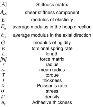
Nomenclature
]
[
A
Stiffness matrix 66A
shear stiffness componentE
modulus of elasticity hE
average modulus in the hoop direction xE
average modulus in the axial directionG
modulus of rigidityK torsional spring rate
L length
[N] force matrix
r radius
rm mean radius
T torque
t thickness
Poisson’s ratio
stress
densityec Adhesive thickness
References
[1] D. Gay, S. V. Hoa, S. W. Tsai. Composite materials: design and application, CRC press, 2004.
[2] P.K. Mallick, S. Newman. Composite materials technology. Hanser Publishers. pp. 206-10, 1990.
[3] A. R. Abu Talib, A. Ali, M. A. Badie and et al. Developing a hybrid, carbon/glass fiber-reinforced, epoxy composite automotive drive shaft. Mater. & Des. Vol. 31, 2010, pp. 514–521.
[4] D.G. Lee, H.S. Kim, J.W. Kim, J.K. Kim. Design and manufacture of an automotive hybrid aluminum/composite drive shaft. Compos. Struct. Vol. 63, 2004, pp. 87–99.
[5] A. Pollard. Polymer matrix composite in drive line applications. GKN technology, Wolverhampton, 1999.
[6] N. Rastogi. Design of composite drive shafts for automotive applications. Visteon Corporation, SAE technical paper series. 2004.2004-01-0485.
0 2 4 6 8 10 12
Weight
Design of a Composite Drive Shaft and its Coupling for Automotive Application, M.R. Khoshravan / 826‐834
Vol. 10, December 2012 834
[7] T. Rangaswamy, S. Vijayrangan. Optimal sizing and stacking sequence of composite drive shafts. Mater. sci., Vol. 11, 2005,India.
[8] A.J. Kumar. Optimum design and analysis of a composite drive shaft for an automobile. Master's degree thesis, Department of Mechanical Engineering, Belkinge Institute of Technology, Sweden, 2007.
[9] M.A.K. Chowdhuri and R. A. Hossain. Design analysis of an automotive composite drive shaft. Int. J. Eng. and Tech., Vol. 2, 2010, pp. 45-48.
[10] M.A. Badie, A. Mahdi, A. M. S. Hamouda. An investigation into hybrid carbon/glass fiber reinforced epoxy composite automotive drive shaft .Mater. & Des., Vol.32, 2011, pp. 1485-1500.
[11] D.G. Lee, N.P. Suh. Axiomatic design and fabrication of composite structures: Applications in robots, machine tools, and automobiles. Oxford University Press, 2006.
[12] S. Pappada, R. Rametto. Study of a composite to metal tubular joint. Department of Materials and Structures Engineering, Technologies and Process, CETMA, Italy, 2002.