Structural Changes in the Surface Layer of Deep Rolled Samples
Due to Thermal Loads
Strunk, R.; Clausen, B.; Zoch, H.-W.
ABSTRACT
Deep ro lling processes initiate p lastic deformat ions in the surface layer. The local characteristics of deformat ion are dependent on the induced stress expressed by the local stress tensor. Equivalent stresses above yield strength cause plastic deformat ion. Additionally the intrinsic energy , e. g. the dislocation density, is enhanced and the residual stress state is changed. The effects to a deep rolled surface from an increase in temperature are mainly dependent on the material, the microstructure, the initial residual stress state, the inclusion density, the distribution of soluted alloying elements and the plastic deformat ion. In the described experiments the interactions between deformation and temperature of the steel grade AISI 4140 (42 CrMo 4) used for all further experiments in a transregional Collaborative Research Center (CRC) were to be examined. The most simple investigation methods were chosen deliberately to allow a better statistical support of correlations between introduced strains and material react ions for a wide variat ion of process parameters. Since the visual effects by light microscopy in AISI 4140 were very s mall, the experiments were repeated with german grade 18 CrNiMo 7-6 (co mparable to AISI 4820). Th is paper focuses on the micro structural changes in defined deep ro lled surface regions due to an increase in temperature. The work described is part of the Co llaborative Research Center “Process Signatures”, collaboration between Bremen Un iversity, Technical University Aachen, Germany and Oklahoma State Un iversity Stillwater, USA.
Keywords:
surface mod ification, mach ining, deep rollingI.
INTRODUCTION
The subproject M02 “Mechanism analysis of material modifications caused by thermal and mechanical loads” of the CRC “Process signatures” aims to explain the interactions between deformation and temperature influences that may occur in machining operations. In literature several works concerning the influence of deformat ion and annealing treatments on residual stresses and the microstructure for various metals can be found. The most accurate results have been determined with residual stress measurements and TEM analysis of the dislocation distribution in the influenced areas. However, if a great number of material variations are to be compared, it is desirable to apply a less sophisticated but faster investigation method. In this paper the possibilities of common light microscopy are worked out. To be able to assess the visible changes in microstructure after deforming and annealing processes it is necessary to produce defined reference samp les and investigate the changes detectable in dependence of load and temperature. Annular samp les of the steel batch 42 CrMo 4 (AISI 4140, FP-annealed), used in the CRC were produced and deep rolled in an ECOROLL® testing device. Though the maximu m pressure in the contact area increased up to 4.490 MPa almost no changes in this steel could be observed in the microscope. To enhance the
visibility of effects the experiments were repeated with an alloy with minor carbon content (18CrNiMo 7-6; AISI 4820). As a further investigation method the hardness measurement in the cross section with a nanoindenter was applied.
II.
STATE OF THE ART
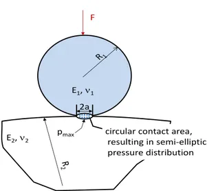
The surface pressure created in the contact zone between workp iece and tool due to deep rolling causes a triaxial stress state, changing with the distance fro m surface. The stress state can be described as a contact between a sphere a cylinder (Hert zian pressure). Figure 1 shows the geometrical conditions in the contact area.
The calculat ion of the stress state from the maximu m contact pressure results in a maximu m equivalent stress beneath the surface. The elastic deformations of the contact zone as well as the depth and amount of maximu m equivalent stress can be calculated with the Hertzian solution for the elastic contact [3]. Start ing fro m the Hert z 's equations Föppl calcu lated the load stresses below the contact surface for different geometries [ 4]. Mesys provides a good working online tool to calculate the elastic stress distribution, the depth and amount of the maximu m shear stress for different geometries in the contact area [1].
Figure 1: Geo metrical conditions in the contact area of a sphere pressed onto a cylinder
If the maximu m equivalent stress increases the yield strength of the material, plastic deformation occurs. Local plastic deformation causes a change in the microstructure and the residual stress state. However, equivalent stresses below yield strength also provoke a change in the condition of the surface layer [2]. The influence of deep rolling on the residual stress state and the microstructure is described in detail by various authors [e.g. 5, 6, 7, 8]. Results have been depicted by measurements of residual stress and the full width at half maximu m of the X-ray interference lines (FWHM) depth profiles and TEM-micrographs of selected areas in the surface. The deformation results in co mpressive residual stresses in the surface area. The level o f these compressive stresses and the decrease with distance from surface is dependent on the condition of the init ial state of the material and the rolling force and contact geometry. TEM micrographs show a strong increase in the dislocation density. Lu finds out that in contrast to shot peened samples, the dislocations in deep rolled samp les tend to cells formation [6].
The named investigation methods have the advantage of high accuracy. On the other hand only very small areas of the treated samples can be investigated. Since in the CRC many samples and variations have to be compared this work aims to investigate less sophisticated methods to rate the surface conditions of machined surfaces in order to be able to assess larger surface regions for a better statistical support for a lot of parameter variat ions.
III.
APPROACH
To investigate the possibility to investigate various thermo-mechanical treat ments in a large surface area annual rings machined fro m the standard CRC-steel batch (42 CrMo 4 (AISI 4140), FP-annealed) and a case hardening steel
deep rolled in an Ecoro ll® testing device with three different loads (corresponding to maximu m elastic contact pressures of 3 390, 3 990 and 4 420 MPa) and partly heat treated. Cross sections of these rings were examined metallographically and by nanoindentation.
The chemical co mposition of the materials investigated is given in table 1. The 4140 steel was investigated in the FP-annealed state. The annealing curve for the applied heat treatment is given in figure 2.
Table 1: Chemical co mposition of the materials (in mass-%)
Steel grade C Cr Ni M o Si M n AISI 4140
42 CrM o 4
0.43 1.09 -- 0.25 0.26 0.74
AISI 4820 18 CrNiM o 7-6
0.19 1.63 1.43 0.287 0.31 0.52
Figure 2: Time-temperature -diagram fo r ferrite-pearlite annealing for AISI 4140 steel
The 4820 grade was delivered in a ferrite-pearlite annealed state. For the experiments rings with an inner diameter of 28 mm and an outer diameter of 46 mm (height 20 mm) were p repared. The rings were assembled in an Ecoroll® testing device (figure 3). The deep-rolling tools were equipped with 6 mm ceramic balls. The rings were deep-rolled at the outer diameter with three different pressures, namely 30 bar, 50 bar and 70 bar. The operating normal force cannot be calculated directly fro m the hydraulic pressure in the device due to oil spill. It was extrapolated fro m force measurements in a range between 100 and 400 bar in a deep rolling device with the same ball diameter to 85, 140 and 190 N.
The corresponding maximu m contact pressures, the maximu m shear stress and the depth of the appearance of this stress were calculated with an online tool [1] for simplified elastic conditions. The results are summarized in table 2.
2a
2a E1, 1
E2, 2
F
Figure 3: Ecoroll®-testing device for deep rolling of annular samp les
Table 2: Hert zian stress and subsurface stresses calculated for elastic contact between ceramic ball
( = 6 mm) and cylinder ( = 46 mm)
normal force
max. contact pressure p0
max. shear stress
max
depth (max)
in ring N MPa MPa µm 190 4 420 1 382 69 140 3 990 1 247 62 85 3 390 1 058 53
Subsequent to the deep-rolling process the rings were separated into eight segments by electric discharge machining. Seven segments underwent annealing for one hour at temperatures between 200 °C and 800 °C. Afterwards the segments were prepared for metallographic analysis. As the visual effects in the 4140 were very small the procedure was repeated with the 4820.
The hardness measurement was carried out with a Fischerscope H100C hardness measurement device. Beneath the deep rolled tracks scans of Martens hardness values were acquired and averaged over the depth.
IV.
RESULTS
Metallographic investigation
Micrographs of the cross sections of the deep rolled tracks on 4140 steel are co mpared in figure 4. Only a very thin deformed layer can be depicted at the surface of the samp les. However this thin layer is also visible on the not deep rolled surface, depicted here in the very left micrograph, which implies that it is caused by former mach ining operations. The maximu m shear stresses do not cause any visible changes in the surface near regions.
Figure 4: Co mparison of metallographic cross sections of deep rolled tracks (steel 4140, FP-annealed), left: unaffected surface
z(
max
)
z(
max
)
z(
max
)
z(
max
)
z(
max
)
z(
max
)
Still, the acting stresses will have caused changes not visible in the microscope. Another possibility to depict changes due to plastic deformation is the recrystallization of a deformed microstructure, since the stored intrinsic energy may cause a development of new crystals. In the following figures only the high resolutions of the micrographs are shown since the interesting microstructures are visible in the first 70 µ m.
Figure 5 co mpares the microstructure beneath the deep rolled tracks after an annealing treat ment at 600 °C fo r 1 hour. At contact pressures of 3 990 and 4 420 M Pa in the direct surroundings of the depth of the occurrence of the maximu m shear stress small ferritic islands can be found. St ill, the differences to the unaffected microstructure are too small to use this effect as an indicator.
Figure 5: Co mparison of metallographic cross sections of deep rolled tracks (steel 4140, FP-annealed) after tempering at 600 °C for 1 hour, left : unaffected surface
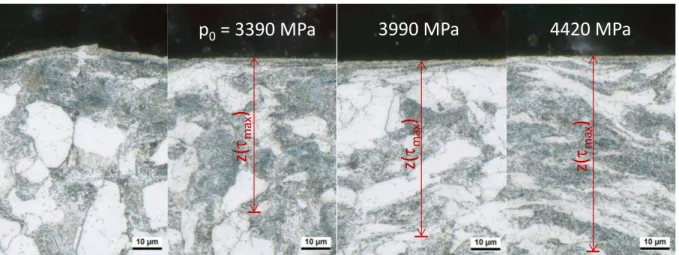
After an annealing treat ment at 700 °C the changes are a b it mo re obvious (Figure 6). The deformed layer in the very surface has recrystallized to a very fine grained seam. The deformed regions beneath the deep rolled tracks show a fine grained structure in the ferritic microstructure at the depth of maximu m shear stresses and at smaller depths for contact stresses of 3 990 and 4 420 MPa. Changes are only visible in
the ferritic grains of the microstructure. At 3 390 MPa no visible changes occur. The minor changes in the micro structure raised the question if the forces are still too small to show a visible effect or if there are other reasons. Furthermo re it was of interest how stronger deformations could lead to more pronounced micro structure changes after annealing. AISI 4820 as a steel with lower carbon content was chosen to complete the investigations.
Figure 6: Co mparison of metallographic cross sections of deep rolled tracks (steel 4140, FP-annealed) after tempering at 700 °C for 1hour, left: unaffected surface
z(
max
)
z(
max
)
z(
max
)
p
0= 3390 MPa
3990 MPa
4420 MPa
z(
max
)
z(
max
)
z(
max
)
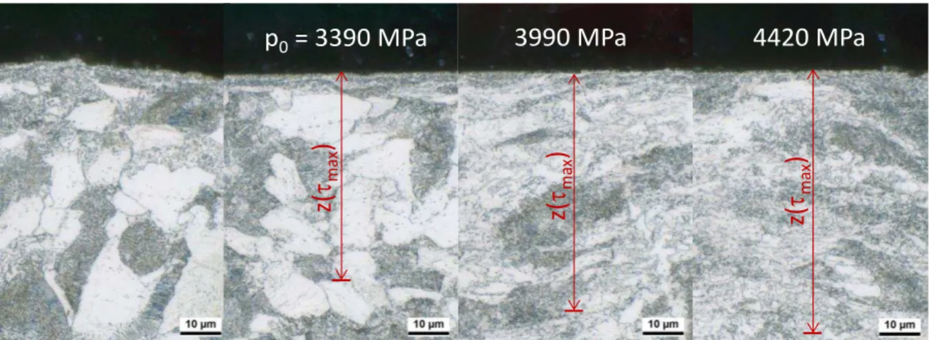
Figure 7 co mpares the microstructure beneath the deep rolled tracks on steel 4820. W ith a maximu m elastic contact stress of 3 390 M Pa no visible microstructure changes can be detected. At contact stresses of 3 990 and 4 420 MPa increasing deformation can be observed. The deformation increases up to the calculated depth of the
maximu m shear stress. In Figure 8 and 9 the microstructure of the deep rolled tracks is shown after annealing at 300 and 500 °C. As expected no changes in the microstructure are detectable. After annealing with 600 °C recrystallized grains are detected in the tracks deep rolled with a maximu m contact stress of 3 990 and 4 420 MPa (Figure 10).
Figure 7: Co mparison of metallographic cross sections of deep rolled tracks (steel 4820, FP-annealed), left: unaffected surface
Figure 8: Co mparison of metallographic cross sections of deep rolled surfaces (steel 4820, FP-annealed), tempered at 300 °C, left : unaffected surface
z(
max
)
z(
max
)
z(
max
)
z(
max
)
z(
max
)
z(
max
)
p
0= 3390 MPa
3990 MPa
4420 MPa
z(
max
)
z(
max
)
z(
max
)
Figure 9: Co mparison of metallographic cross sections of deep rolled surfaces (steel 4820, FP-annealed), tempered at 500 °C, left : unaffected surface
Figure 10: Co mparison of metallographic cross sections of deep rolled surfaces (steel 4820, FP-annealed), tempered at 600 °C, left : unaffected surface
At 700 °C the microstructure of the deep rolled track with a maximu m contact pressure of 3 390 MPa shows small newly build grains at the depths of the maximu m shear strength. Figure 11 shows that the size of newly build ferrite grains cannot be a one-to-one indicator for deformat ion.
In the ferrit ic reg ions of the samples very small new grains have built where the minimu m deformation degree for the annealing temperature has been exceeded. In the pearlitic reg ions no grain refinement occurs.
Figure 11: Co mparison of metallographic cross sections of deep rolled surfaces (steel 4820, FP-annealed),
z(
max
)
z(
max
)
z(
max
)
p
0= 3390 MPa
3990 MPa
4420 MPa
z(
max
)
z(
max
)
z(
max
)
p
0= 3390 MPa
3990 MPa
4420 MPa
z(
max
)
z(
max
)
z(
max
)
After annealing at 800°C the microstructure shows no differences between deformed and not deformed regions (Figure 12). Due to the austenitization the microstructure is
completely restored. The grains in the formerly deformed regions appear smaller than above and below. Ho wever, the differences are too small to excerpt an indicator fro m these measures.
Figure 12: Co mparison of metallographic cross sections of deep rolled surfaces (steel 4820, FP-annealed), tempered at 800 °C, left : unaffected surface
Har dness measure ment
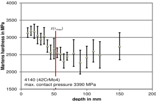
Figures 13, 14, and 15 show the diagrams of the hardness measurement results beneath the deep-rolling tracks on steel 4140. The red line in all figures marks the depth where the calculated maximu m shear stress appears. The Martens hardness of the bulk material of the AISI 4140 is about 2 800 M Pa. Figure 13 shows the hardness curve under the track with the maximu m contact pressure of 3 390 M Pa. The curve has a maximu m in a depth of about 15 µ m under the surface. The hardness at that point is about 3 200 MPa. With further distance from the surface the hardness decreases to a minimu m in a depth of 75 till 80 µ m. Afterwards the hardness increases again slightly.
Figure 13: Hardness depth profile beneath the deep rolled surface (steel 4140 FP-annealed, max. contact pressure 3 390 MPa)
The resulting micro-hardness of the deep-rolling process with a maximu m contact pressure of 3 990 MPa is depicted in figure 14. Again a maximu m hardness is visible at a distance from the surface of about 40 µ m. The hardness increases up to 2 900 MPa. In between 40 µ m and 80 µ m the hardness decreases and reaches a min imu m. Up to a depth of 150 µ m the hardness increases slightly.
Figure 14: Hardness depth profile beneath the over rolled surface (steel 4140 FP-annealed, max. contact pressure 3 990 MPa)
Figure 15 shows the micro-hardness after a deep-rolling process with a maximu m contact pressure of 4 420 M Pa. The course of the curve is similar to those depicted in figures 13 and 14. There is a clear maximu m of hardness in a distance fro m the surface of about 30 µ m. The hardness reaches a value of 3 000 MPa. With increasing distance from the surface the hardness decreases and hits a minimu m in a depth of 80 µ m. Fro m the minimu m on there is a slight increase in the hardness up to 2 800 MPa in 150 µ m depth.
z(
max
)
z(
max
)
z(
max
)
p
0= 3390 MPa
3990 MPa
4420 MPa
1500 2000 2500 3000 3500 4000
0 50 100 150 200
Mar
tens har
dn
es
s in
MPa
depth in mm
z(max)
4140 (42CrMo4)
max. contact pressure 3390 MPa
1500 2000 2500 3000 3500 4000
0 50 100 150 200
Mar
tens har
dn
es
s in
MPa
depth in mm
z(max)
4140 (42CrMo4)
Figure 15: Hardness depth profile beneath the over rolled surface (steel 4140 FP-annealed, max. contact pressure 4 420 MPa)
Figures 16, 17, and 18 show the micro-hardness curves of the steel 4820 deep-ro lled at three different pressures. The red line again resembles the depth of the appearance of the maximu m shear stress. The bulk material without any surface modification has a hardness of about 2 400 M Pa. In figure 16 the micro-hardness development due to deep-rolling with a maximu m contact pressure of 3 390 MPa is depicted. A slight increase of the hardness with increasing distance fro m the surface is visible. A possible maximu m of hardness is found around 50 µ m fro m the surface. The hardness value goes up to almost 2 800 MPa at that point. Afterwards the hardness decreases slowly until it reaches the value of the bulk material.
Figure 16: Hardness depth profile beneath the over rolled surface (steel 4820 FP-annealed, max. contact pressure 3 390 MPa)
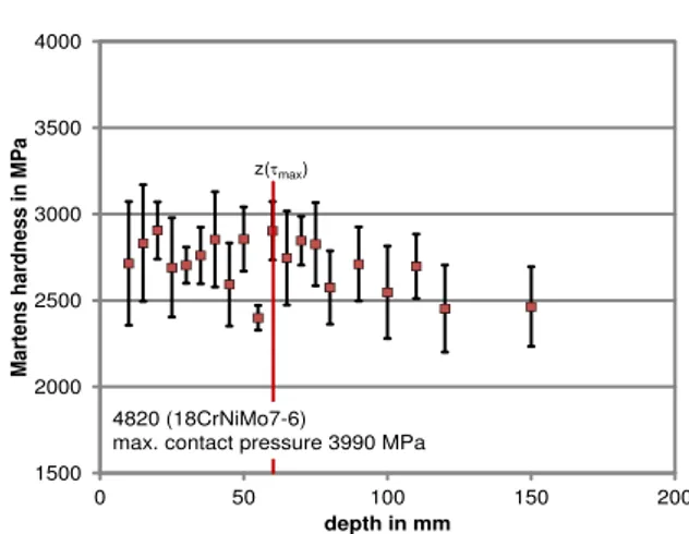
The hardness measurement after deep-rolling with a maximu m contact pressure of 3 990 MPa is shown in figure 17. A s mall trend in the hardness values is visible as a slight increase towards a maximu m in about 60 µ m depth. At that distance from the surface the value of the hardness is 2 900 MPa. With increasing depth the values
Figure 17: Hardness depth profile beneath the over rolled surface (steel 4820 FP-annealed, max. contact pressure 3 990 MPa)
The shape of the micro-hardness curve shown in figure 18 shows the strongest impact of the deep-rolling process. The maximu m contact pressure in this case calculates to 4 420 M Pa. With increasing distance from the surface the hardness values clearly increase until they reach a maximu m in a depth between 50 µ m and 60 µ m. The hardness values reach up to 3 400 MPa. The curve decreases again fro m the maximu m hardness.
Figure 18: Hardness depth profile beneath the over rolled surface (steel 4820 FP-annealed, max. contact pressure 4 420 MPa)
V.
DISCUSSION
The results of this investigation show that a quantified characterizat ion of the surface region beneath a deep rolled t rack on the CRC standard steel 4140 is not possible with conventional microscopy. A subsequent recrystallization treatment generates a local grain refinement, but in the standard steel the effect is so small that the discovery of the newly build grains is no reliable measured variable. In the steel 4820 the effect is 1500
2000 2500 3000 3500 4000
0 50 100 150 200
Mar
tens har
dn
es
s in
MPa
depth in mm z(max)
4140 (42CrMo4)
max.contact presssure 4420 MPa
1500 2000 2500 3000 3500 4000
0 50 100 150 200
Mar
tens har
dn
es
s in
MPa
depth in mm z(max)
4820 (18CrNiMo7-6)
max. contact pressure 3390 MPa
1500 2000 2500 3000 3500 4000
0 50 100 150 200
Mar
tens har
dn
es
s in
MPa
depth in mm 4820 (18CrNiMo7-6)
max. contact pressure 3990 MPa z(max)
1500 2000 2500 3000 3500 4000
0 50 100 150 200
Mar
tens har
dn
es
s in
MPa
depth in mm
z(max)
4820 (18CrNiMo7-6)
rolling process increases up to the calculated depth of the maximu m shear stress. Since the maximu m deformation is expected at the depth of the maximu m shear stress an additional frict ion effect can be assumed, since friction shifts the depth of the maximu m shear stress to lesser depths. Still, a measure for the severity of the deformation cannot be extracted fro m the degree of recrystallization since the recrystallization effect occurs only in the ferritic structure fractions. In the pearlitic structure fractions the recrystallization is hindered by carbides. The recrystallized reg ions are therewith not definite.
The micro-hardness measurement in the standard steel does also not reveal the expected result in the standard steel grade. While the deep rolling of steel 4820 provokes with increasing pressure an increasing maximu m in Martens hardness in a depth that may be assumed as depth of the maximu m equivalent stress, the hardness results in the standard 4140 steel reveal a minimu m in Martens hardness at this position. Lu [6] also observed a hardness decrease in deep rolled surface of 4140 steel with higher strength. In the same sample an increase of residual co mpressive stresses but a decrease in FWHW was measured in this region. Lu exp lained that fine distributed carbides may hinder the format ion of dislocation cells, typical for deep rolled surfaces.
In the investigated microstructure the carbides are not finely distributed due to industrial production. Still, the presence of carbides seems to influence the steel’s behavior in the deep ro ll process.
VI.
CONCLUSIONS
The results of this investigations show that it is not possible to reduce the investigation effort to characterize the surface state of machined samples within this project, since it would inevitably be related to loss in informat ion needed to formulate the process signature for this process. The next step will be to investigate the dislocation and residual stress state of defined deformed and heat treated samples to develop the needed correlations.
ACKNOWLEDGEMENTS
The authors would like to thank the Co mpany Ecoro ll® for provid ing an “Ecoro ll® testing device” to initiate locally defined deep rolling conditions.
Further the authors gratefully acknowledge the financial support of the research work by the German Research Foundation (DFG) within the transregional Collaborative Research Center SFB/TRR 136 “Process Signatures”, sub project M02.
REFERENCES
[1]. MESYS A G: Calculat ion of contact stress. Online Tool for the calculation of Hert zian pressures for point or line contact. https://www.mesys.ch/?page_id=54 [2]. Vöhringer, O.: Relaxation of residual
stresses by annealing or mechanical treatment. In: Advances in surface treatments, Vo l. 4: International Gu idebook on residual stresses, Ed.: Niku Lari, A., Pergamon Press (1987)
[3]. Hert z, H. R.: Über die Berührung elastischer Körper (On Contact Between Elastic Bodies), in Gesammelte Werke (Co llected Works), Vol. 1, Leip zig, Germany (1895)
[4]. Föppl, L.: Der Spannungszustand und die Anstrengung des Werkstoffes bei Berührung zweier Körper. Forsch. Ing. Wes. 7 (1936), 210-215
[5]. Altenberger ,I. : M ikrostrukturelle Untersuchungen mechanisch randschichtverfestigter Bereiche schwingend beanspruchter metallischer Werkstoffe, Dissertation, Universität Gesamthochschule Kassel (2000)
[6]. Lu, H., Scholtes, B.; Macherauch, E.: Randschichtzustände von normalisiertem und vergütetem 42CrMo4 nach konsekutiven Kugelstrahl- und Festwalzbehandlungen.
Materialwissenschaften und Werkstofftechnik 23 (1992), pp. 388-394 [7]. Hoffmann, F.: Mikrostruktur und
Schwingfestigkeit von Ck45 nach ko mbinierter mechanischer und thermochemischer
Randschichtverfestigung. VDI-Fortschrittberichte, Reihe 5: Grund- und Werkstoffe Nr.123, VDI-Verlag, Düsseldorf (1987).