Reinement and fracture mechanisms of as-cast
QT700-6 alloy by alloying method
*Ying-dong Qu
Male, born in 1975, Professor, Ph.D. supervisor. His research interests mainly focus on cast alloys.
E-mail: [email protected]
Received: 2016-02-21; Accepted: 2016-12-08
Min-qiang Gao, *Ying-dong Qu, Rong-de Li, Ke Jiang, and Jun-hua You
School of Materials Science and Engineering, Shenyang University of Technology, Shenyang 110870, China
D
uctile cast iron has been widely applied in automobile gears and cylinders due to its many desirable properties including high strength, outstanding resistance to wear and oxidation, and high lowability [1]
. Nevertheless, the common as-cast ductile iron (QT400-18 or QT700-2) cannot simultaneously achieve high strength and toughness in industrial fields [2-3], mainly because a high strength usually corresponded to a low toughness [4-5]. In the past few years, researchers have been exploring heat treatment methods to improve mechanical properties of ductile cast iron [6-7]. Gonzaga et al. [8] investigated the efect of heat treatment on the ratio of pearlite/ferrite, and it was found that the tensile strength and elongation of ductile iron increased to 687 MPa and 11%, respectively, after normalizing heat treatment at 850 ºC for 1 h, and subsequently cooling in air. Putatunda et al. [9-10] examined microstructures and properties of austempering ductile iron (ADI), and results showed that their performance could be comparable to
Abstract:
The as-cast QT700-6 alloy was synthesized with addition of a certain amount of copper, nickel, niobium and stannum elements by alloying method in a medium frequency induction furnace, aiming at improving its strength and toughness. Microstructures of the as-cast QT700-6 alloy were observed using a scanning-electron microscope (SEM) and the mechanical properties were investigated using a universal tensile test machine. Results indicate that the ratio of pearlite/ferrite is about 9:1 and the graphite size is less than 40 μm in diameter in the as-cast QT700-6 alloy. The predominant reinement mechanism is attributed to the formation of niobium carbides, which increases the heterogeneous nucleus and hinders the growth of graphite. Meanwhile, niobium carbides also exist around the grain boundaries, which improve the strength of the ductile iron. The tensile strength and elongation of the as-cast QT700-6 alloy reach over 700 MPa and 6%, respectively, when the addition amount of niobium is 0.8%. The addition of copper and nickel elements contributed to the decrease of eutectoid transformation temperature, resulting in the decrease of pearlite lamellar spacing (about 248 nm), which is also beneicial to enhancing the tensile strength. The main fracture mechanism is cleavage fracture with the appearance of a small amount of dimples.Key words:
as-cast QT700-6 alloy; microstructure; graphite; reinement; pearlite lamellar spacingCLC numbers: TG143.5 Document code: A Article ID: 1672-6421(2017)01-016-06
that of carbon steels. Although ADI can simultaneously achieve the requirement of high strength and high toughness, the heat treatment process is tremendously complex and will increase production costs [10].
Table 1: Chemical compositions of as-cast QT700-6 alloy (wt.%)
C Si Mn S P Cu Ni Sn Nb Fe
3.50 2.24 0.06 0.023 0.031 0.45 0.86 0.01 0.75 Balance
used as spheroidizing agent and nucleating agent, respectively. The pouring temperature was 1,450 ºC. Dimensions of the Y type block specimen are shown in Fig. 1. The tensile specimen (Fig. 2) and metallographic specimen (10 mm × 10 mm × 10 mm) were cut from the bottom of the Y type block specimen. Metallographic specimens were etched with 4% nitric acid alcohol for microstructural observation.
Microstructures were observed using scanning-electron microscopes (SEM, Hitachi S-3400N and Hitachi TM3030) equipped with energy-dispersive spectrometers (EDS). Table 1
Fig. 2: Dimensions of tensile specimen (mm)
lists the main chemical compositions of as-cast QT700-6 alloy. Carbon equivalent was measured using a CSA-2000 analyzer and tensile testing was performed using a universal tensile machine (WGW-100H) according to GB-T-2002 with a tensile speed of 1.5 mm•min-1.
2 Results and discussion
2.1 Reinement of graphite and niobium
carbides in as-cast QT700-6 alloy
Figure 3 shows the microstructure of as-cast QT700-6 alloy. According to GB9441-1988, the grade of spheroidization and graphite size is level 2 and 6, respectively, as shown in Fig. 3(a). Figure 3(b) shows the typical bull's eye microstructure, i.e. the ferrite is encircled around the graphite ball and outer layer is pearlite. Ductile cast iron matrix is usually a mixture of ferrite and pearlite in the as-cast condition [15, 16]. The content of pearlite and ferrite was measured using the image processing method in the LIM-2000 image analysis software, and the ratio of pearlite/ ferrite was about 9:1 in the as-cast QT700-6 alloy. Moreover, graphite distribution is relatively homogeneous in different viewing fields in the as-cast QT700-6 alloy. It is well known that the smaller the graphite, the better the mechanical properties of ductile cast iron in a certain range. Therefore, the size and distribution of graphite play an important role in improving mechanical properties of ductile cast iron [17-19]. Generally, graphite with a diameter greater than 50 µm emerges in liquid areas in traditional ductile cast iron according to the Fe-C phase diagram [12]. However, graphite with a diameter less than 40 µm was formed due to the reinement with the addition of niobium element (Fig. 3a).
The ainity between niobium and carbon is relatively strong, leading to the formation of NbC. The reaction between niobium
and carbon in the medium frequency induction furnace may take place as follows [20]:
[Nb] + [C] = NbC(S)
For non-equilibrium solidification, the Gibbs free energy (ΔGNbc ) can be expressed as
[21] :
where ΔGNbC θ
is standard equilibrium Gibbs free energy, fNb and fC are the activity coefficient of niobium and carbon, respectively. According to equation (2), the formation
temperature T of NbC can be obtained when ΔGNbC =0, if the niobium content is a deinite value. Then, T is ~1,180 °C, which is above the eutectoid transformation temperature. It can be proved that niobium carbides were formed in the liquid state.
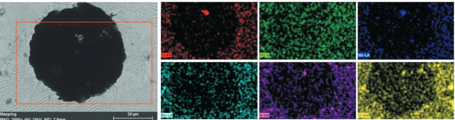
Figure 4 shows the energy spectrum of the graphite core in as-cast QT700-6 alloy. In general, sulides and oxides can act as nucleus to promote nucleation [8, 12]. Niobium, sulfur, oxygen and titanium elements are discovered in the graphite core. The niobium carbides formed in the liquid can also act as the heterogeneous nucleus, leading to the increase of nucleation rate and refinement of graphite. Moreover, niobium hinders the carbon from moving during the solidiication which also restricts the growth of graphite, and it can also reduce the average diameters of eutectic cells in a certain range [13].
For purposes of comparison, ductile iron with 0.6% niobium (1)
ΔGNbC = ΔGNbCθ + RTln
α[C]× α[Nb]
1
Fig. 3: Microstructure of as-cast QT700-6 alloy
Fig. 4: Energy spectrum of graphite core in as-cast QT700-6 alloy
Fig. 5: Tensile curves and sizes of graphite with different amounts of niobium addition
(a) Grade of spheroidization and graphite size (b) Typical bull's eye microstructure
addition was also prepared while other conditions remained the same. Figure 5 shows the tensile curves and graphite sizes of ductile cast iron with different niobium additions. Obviously, tensile properties of the alloy with 0.8% niobium (actual content of 0.75% niobium) are better than those of the alloy with 0.6% niobium, and the graphite size of the alloy with 0.8% niobium is signiicantly less than that of with 0.6% niobium. Increasing the content of niobium in a certain range is beneicial to improving the mechanical properties of ductile cast iron. However, the addition amount of niobium should be strictly controlled as niobium carbides will be formed around
the grain boundaries with too much niobium addition, and as a result, decrease the toughness of ductile iron cast.
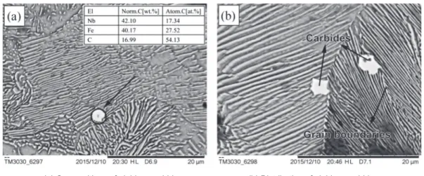
Fig. 6: Element composition and distribution of niobium carbide
Fig. 7: Morphology and spacing of local pearlite lamellar
(a) Compositions of niobium carbides (b) Distribution of niobium carbides
carbide particles will be detected around the grain boundaries in as-cast QT700-6 alloy, which deteriorate the toughness of ductile iron. In addition, niobium is very expensive, so there is no point to further increase the niobium content. Ductile iron cast with better comprehensive performance (the as-cast QT700-6 alloy) can be synthesized when the addition amount of niobium is 0.8%, and tensile strength and elongation of the as-cast QT700-6 alloy are over 700 MPa and 6%, respectively (Fig. 5a).
2.2 Reinement of lamellar pearlite in as-cast
QT700-6 alloy
In general, pearlite lamellar spacing mainly depends on cooling rate, and the faster the cooling rate, the smaller the lamellar spacing [13]. Eutectoid transformation temperature of the alloy decreases with the addition of alloying elements, leading to an increase in undercooling (ΔT) and a decrease in pearlite lamellar spacing (S0). According to the classic equation proposed by Marder [13]:
S0 = C/ΔT (3) where C is a constant (= 8.02×10³ nm•K), ΔT is undercooling, i.e. the difference between eutectoid transformation t e m p e r a t u r e a n d e q u i l i b r i u m c r i t i c a l t r a n s f o r m a t i o n temperature of pearlite.
Figure 7(a) shows the morphology of local pearlite lamellar
in the as-cast QT700-6 alloy. It can be seen that the pearlite lamellar is composed of ferrite and cementite in alternate growth formation. It is clearly observed that the pearlite lamellar in this region forms in almost the same orientation. The pearlite lamellar spacing (L) can be approximately calculated as follows:
L = πdc/Mn (4)
where dc is the diameter of measuring circle, n is cut-of points
of measuring circle and carbide, M is the magniication. The pearlite lamellar spacing of this area could be calculated by changing the diameter of measuring circle. Through adjusting the size of metallography to 150 mm × 112.5 mm in the drawing software, measuring circles with diferent diameters (10 mm, 15 mm, 20 mm, 25 mm, 30 mm and 35 mm) are marked in Fig. 7(a) to calculate the lamellar spacing. Figure 7(b) shows the relationship between diameter of measuring circle and lamellar spacing. Then, the average value is calculated from different measuring circles, and the local pearlite lamellar spacing is approximate 248 nm, indicating that the pearlite is in the form of sorbite.
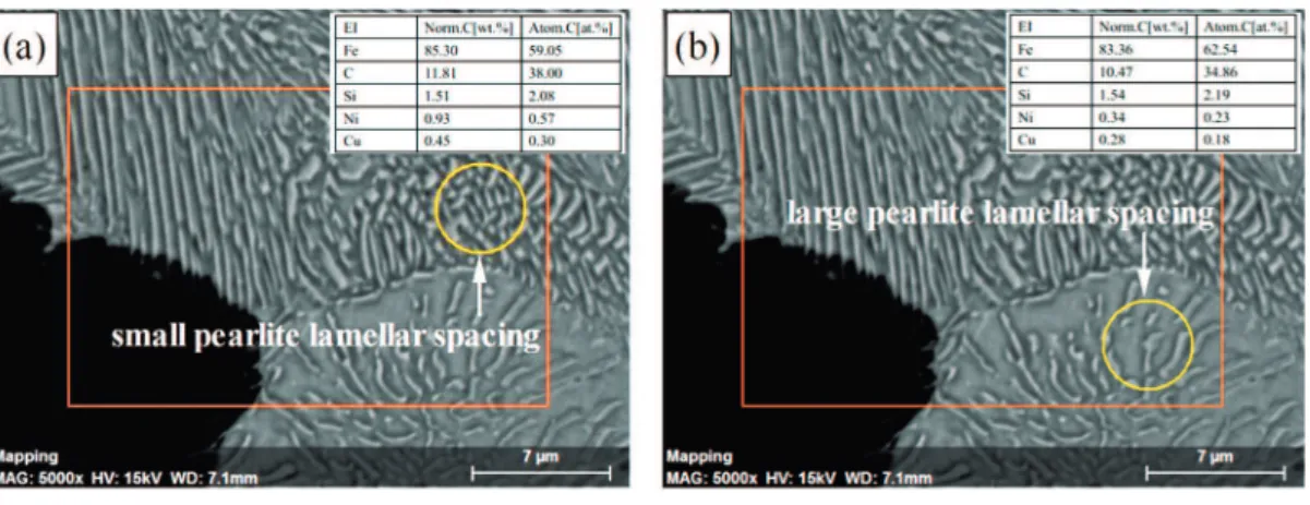
Figure 8 shows the efect of alloying elements on pearlite lamellar spacing. Chemical compositions are conirmed using EDS in diferent regions as marked in Fig. 8. It is noticed that copper and nickel elements have a great effect on pearlite
(a) Local pearlite lamellar morphology (b) Pearlite lamellar spacing
Fig. 8: Effect of alloying elements on pearlite lamellar spacing
Fig. 9: Fracture morphology of as-cast QT700-6 alloy
(a) Small pearlite lamellar spacing (b) Large pearlite lamellar spacing
(a) Cracks propagation (b) River-pattern fracture and ladder morphology lamellar spacing. The content of nickel and copper is higher
in the region marked in yellow circle in Fig. 8(a), the pearlite lamellar spacing of this region is smaller. While pearlite lamellar spacing of the neighboring region [yellow circle in Fig. 8(b)] is larger, and the content of nickel and copper is lower than that of the pearlite lamellar spacing in the Fig. 8(a). This is because the undercooling of the alloy may increase with the addition of alloying elements (Cu and Ni) [12], leading to the decrease of pearlite lamellar spacing, which is beneicial to improving the tensile strength of ductile cast iron.
2.3 Tensile fracture behavior of as-cast
QT700-6 alloy
Figure 9(a) shows fracture morphology of the as-cast
QT700-6 alloy from the crack source to extended fracture. A small amount of dimples can be observed, which is conducive to the increase of elongation. Figure 9(b) shows river-pattern fracture and ladder morphology. The cracks' location is mainly at the interface between graphite and pearlite due to the low interfacial energy. Therefore, the graphite separates from the matrix under the efect of stress. With the increase of stress, cracks propagate to the other cracks formed by the neighboring graphite separating from the matrix. When the applied stress is over the fracture strength of pearlite, the fracture occurs. As can be seen from Fig. 9, almost no plastic deformation can be observed, indicating that the main fracture mechanism of as-cast QT700-6 alloy is cleavage fracture.
Generally, fracture morphology displays continuous river-pattern morphology and the direction of crack propagation is along river-pattern shape in the ductile cast iron with pearlite matrix [22, 23]. In this work, when the pearlite matrix is subjected to the applied stress, plastic deformation mainly occurs at the ferrite regions and cementite layers, hindering the dislocation slip. For the pearlite lamellar in ductile cast iron, the maximum slip distance equals to lamellar spacing. Therefore, the smaller the lamellar spacing, the more the phase interfaces of the cementite and ferrite within a certain range, which is beneicial to the enhancement of the strength, i.e., plastic deformation
resistance will signiicantly increase, leading to an increase of strength and hardness of ductile iron.
3 Conclusions
(1) The as-cast QT700-6 alloy could be synthesized by alloying method, and the ratio of pearlite/ferrite is about 9:1 and the diameter of graphite is less than 40 μm.
dimples.
References
[1] Di Cocco V, Iacoviello F, Rossi A, et al. Graphite nodules and fatigue crack propagation micromechanisms in a ferritic cast ductile iron. Fatigue & Fracture of Engineering Materials & Structures, 2013, 36(9): 893-902.
[2] Qi K, Yu F, Bai F, et al. Research on the hot deformation behavior and graphite morphology of spheroidal graphite cast iron at high strain rate. Materials & Design, 2009, 30(10): 4511-4515.
[3] Ji C, Zhu S. Study of a new type ductile iron for rolling: composition design (1). Materials Science and Engineering A, 2006, 419(1): 318-325.
[4] Martinez Celis M, Valle N, Lacaze J, et al. Microstructure of as cast reinforced ductile iron. International Journal of Cast Metals Research, 2011, 24(2): 76-82.
[5 Refaey A, Fatahalla N. Effect of microstructure on properties of ADI and low alloyed ductile iron. Journal of Materials Science, 2003, 38(2): 351-362.
[6] Murcia S C, Paniagua M A, Ossa E A. Development of as-cast dual matrix structure (DMS) ductile iron. Materials Science and Engineering A, 2013, 566(3): 8-15.
[7 Martins R, Seabra J, Magalhaes L. Austempered ductile iron (ADI) gears: Power loss, pitting and micropitting. Wear, 2008, 264(9): 838-849.
[8] Gonzaga R A. Influence of ferrite and pearlite content on mechanical properties of cast ductile irons. Materials Science and Engineering A, 2013, 567(4): 1-8.
[9] Putatunda S K. Development of austempered cast ductile iron (ADI) with simultaneous high yield strength and fracture toughness by a novel two-step austempering process. Materials Science and Engineering A, 2001, 315(1): 70-80.
alloys made of ball-milled powders. Archives of Metallurgy & Materials, 2014, 59(3): 947-950.
[15] Martínez R A. Fracture surfaces and the associated failure mechanisms in ductile iron with different matrices and load bearing. Engineering Fracture Mechanics, 2010, 77(14): 2749-2762.
[16] Nilsson K F, Blagoeva D, Moretto P. An experimental and numerical analysis to correlate variation in ductility to defects and microstructure in cast ductile iron components. Engineering Fracture Mechanics, 2006, 73(9): 1133-1157.
[17] Labrecque C, Gagne M. Ductile iron: ifty years of continuous
development. Canadian Metallurgical Quarterly, 1998, 37(5): 343-378.
[18] Kocatepe K, Cerah M, Erdogan M. Effect of martensite volume fraction and its morphology on the tensile properties of ferritic ductile iron with dual matrix structures. Journal of Materials Processing Technology, 2006, 178(1): 44-51.
[19] Chaengkham P, Srichandr P. Continuously cast ductile iron: processing, structures, and properties. Journal of Materials Processing Technology, 2011, 211(8): 1372-1378.
[20] Aksoy M, Kuzucu V, Korkut M H. The influence of strong carbide-forming elements and homogenization on the wear resistance of ferritic stainless steel. Wear, 1997, 211(2): 265-270.
[21] Filipovic M, Kamberovic Z, Korac M, et al. Wear resistance and dynamic fracture toughness of hypoeutectic high-chromium white cast iron alloyed with niobium and vanadium. Materiali in Tehnologije, 2014, 48(3): 343-348.
[22] Hebel J, Dieringer R, Becker W. Modelling brittle crack formation
at geometrical and material discontinuities using a inite fracture
mechanics approach. Engineering Fracture Mechanics, 2010, 77(18): 3558-3572.
[23] Cavallini M, Di Bartolomeo O, Iacoviello F. Fatigue crack propagation damaging micromechanisms in cast ductile irons. Engineering Fracture Mechanics, 2008, 75(3): 694-704.
This work was inancially supported by the Program for Innovative Research Team in University of Liaoning Province (grant no.