A R C H I V E S
o f
F O U N D R Y E N G I N E E R I N G
Published quarterly as the organ of the Foundry Commission of the Polish Academy of Sciences
ISSN (1897-3310) Volume 12 Issue 1/2012
43 – 48
8/3
Continuous Modification of Cast Iron
by the FLOTRET Method
A. Hanus
a*, P. Hanusová
ba
Department of Metallurgy and Foundry Engineering, Faculty of Metallurgy and Material Engineering,
b
Department of Thermal Engineering, Faculty of Metallurgy and Material Engineering,
VŠB – Technical University of Ostrava, Czech Republic
*Corresponding author. E-mail address: [email protected]
Received 16.04.2012; accepted in revised form 02.07.2012
Abstract
Increasing demands on the utility properties of materials used for castings have led to the production of cast iron with a modified shape of graphite, where the required properties are achieved by a change in graphite shape, its size and layout, and a change in the basic structure of the metal. This paper is focused on the continuous method of producing spheroidal graphite FLOTRET.
In the introductory section is summarized the theoretical foundations of the secondary treatment of cast irons, especially the FLOTRET flow method, describes the advantages and disadvantages of the method. The practical part is divided into laboratory and operational tests. Laboratory experiments were conducted on a laboratory-type modifier FLOTRET chamber, which was designed and hydraulically optimized. Experiments were focused on the effects of pressure altitude and amount of modifier on the residual values of magnesium, as conditions for a successful modification. The method was tested in two foundries under operating conditions and in one of them was observed a long-term modification process.
Key words: Innovative Foundry technologies and materials; Product development; Cast iron with spheroidal graphite; Modification of
graphite shape; FLOTRET
1. Introduction
Currently, there are about 210 patented methods of spheroidal graphite cast iron in production, and it is not exactly known the percentage share of each technology modifications on the overall production of ductile iron. One of these production methods is a modification of the flow FLOTRET. [1]
This method is not used so often but it certainly deserves greater attention and popularization by the producers of ductile iron castings because of low investment, simplicity and reliability.
2. Cast iron
Iron castings, such as a construction material, still maintain a high standard of usability, as they provide a wide variety of utility
properties and also because they require less expensive metallurgy or technology, and in many cases they provide more economical solutions. Increasing demands on the materials utility properties for castings have led to the introduction of cast iron with a modified shape of graphite into the production, where the required properties are achieved by change of graphite shape, its size and layout, and change of the metal basic structure.
Cast iron with spheroidal graphite (ductile iron) is industrially used for more than 60 years. Ductile iron gradually, as it developed its properties, replaces cast iron, malleable cast iron, unalloyed cast steel and other materials, and even at the same time replaces other technologies by foundry manufacturing technology.
but also effects physical properties such as thermal conductivity, coefficient of thermal expansion, corrosion, and technological properties like welding and machining possibilities, and ultimately changes the casting properties of cast iron. Cast iron is becoming fierce with appropriate mechanical properties. Importantly, these properties of spheroidal graphite cast can be achieved in the state or by subsequent heat treatment. Therefore, the modification has the far-reaching importance for the usage of spheroidal graphite cast irons as a structural material because the mechanical properties of these cast irons are equivalent to the mechanical properties of alloy steels [2][3].
Fig. 1. Structure of cast iron with lamellar graphite
Fig. 2. Structure of cast iron with spheroidal graphite
2.1. Methods of production of Ductile iron
Currently, there are about 210 patented ways of adding modifiers to the molten cast iron; operational use represents about 40 to 50 ways to manufacture ductile iron. Requirements upon some security of the modification can be summarized as follows:
reliability - high stability of the manufacturing process efficiency - percentage of high use of modifier
low cost - low cost methods for the introduction into the production process, and consequently very low cost of production of Ductile iron
environmental and sanitary conditions
According to the main characters methods of graphite shape modifying are divided into sandwich, converter, submerged, and filled profiles. The FLOTRET method belongs to the flow modification methods. In this manufacturing method modification takes place during the casting of molten metal from melting aggregate and there are two ways, either modification occurs directly in the gating system of the mould (In Mould), or metal is poured during a specially modified reaction chamber in which the modifier is placed, and from here into the ladle (called the FLOTRET way – Fig. 3).
Flow modification methods are very powerful because of above-mentioned conditions and the dynamic effects of the flowing metal, which ensures a good dissolution of modifier but requires a low sulphur content in the cast iron (less than 0.015%), desulphurization during the modification is not possible.
Acquisition investment costs are low or minimum; by use of modification in the reaction chamber in the mould only the gating system has to be modified.
Fig. 3. Modification by the FLOTRET Method
A granular modifier in the form of master alloys, containing more than 5% Mg and higher content of Ca (up to 2%), is inserted into the reaction chamber which is located in the mould parting of the gating system. A separate processing chamber, in which the modification takes place, has the character of the tundish and it is split into the reaction and mixing space by partition. Modified cast iron flows from the reaction chamber into the ladle, where we can inoculation immediately and after slag removing it is possible to cast, since the ladle can be used as a casting ladle. [1][4][8][9][10][11][12]
The FLOTRET method was patented by Methods & Materials Co., Ltd. in 1974. At present, various types of equipment are produced or modification to the FLOTRET method, the most common and usually operated device in Czech Republic is shown in Fig. 4.
The device is constructed from metal sheet and is lined by refractory fireclay bricks or rammed. The internal working part of the device consists of a funnel, reaction chamber, mixing chamber and outlet groove. The reaction and mixing chambers are covered with a removable cover. The funnel is connected with the reaction chamber by an inlet channel with cross-section S3. The reaction
chamber is defined by a plan area (SRC) and is separated from the
mixing chamber by an overflow partition (S2) and drain (S1). The
chamber cover is lined by castable and is attached to the tundish by cam locks, which guarantee fast and firm sealing of the reaction chamber. This whole device is placed on a pedestal with
tilt up to 15°. Feeder for graphite inoculation into the stream of
metal is placed above the outlet groove.
2.2. Advantages of the FLOTRET method
Savings can be achieved by flow modification in the reaction chamber:
Modification ladle is not used, thus the spill over from modification into the casting ladle is completely eliminated, and therefore there is no loss of temperature that the
modifications carried out routinely as high as 60°C or more.
It is possible to decrease overheating of the melt temperature in the furnace (estimated energy savings of
approximately 5 ÷ 7%) and thus improve metallurgical
quality of melt.
Energy (gas) savings for modification ladle pre-heating. Costs elimination for re-lining of modification ladle. High stability of the modification process (there is no rising of the modifier to the surface and burnout by pyro-effect). The stability of the process is verified by steady structural and mechanical properties of ductile iron.
High utilization MgSi ligatures, which is comparable with the Tundish-cover method.
Smaller amounts of slag as a result of the modification
Fig. 4. Scheme FLOTRET chamber: S1– outlet cross
section, S2– the ramp section, S3– the input section,
SRC– the area of the reaction chamber
2.3. Disadvantages of the FLOTRET method
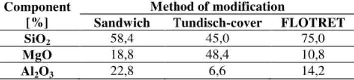
Comparison of selected slag components from sandwich method, from modification ladle Tundish cover and from reaction chamber shows the Table 1. The results of slag analyzes obtained in real foundries conditions show that slag from the reaction chamber is significantly more acidic, thus slag can be more fluid, and thus scrap may increase. Acidic nature of slag, which is more fluid, requires attention during slag removing and needs to use the thickeners before casting into the moulds. This method is not recommended for furnaces of more then 3 tons capacity due to worse manipulation with the equipment. [10][11]
2.4. The choice of the reaction chamber shape
and size
The FLOTRET flow method of the modification was based on the method In-Mould. Selection the main dimensions of the reaction chamber is based on the weight of the initial melt to be adjusted by modifying into the spheroidal graphite cast iron. This weight is determined by the size of the melting aggregate, size of the casting or transport ladle and not least the need that all
modified amount has to be casted in 22 minutes (time required for manipulation and casting times). This is the time of modification effect to change the shape of graphite. The main requirement on the flow modification methods is to ensure the efficiency of modifier dissolution in a way that the intensity of Mg evaporation is reduced. [4][9][10][12]
Table 1.
Comparison of the transformed components of slag in the system SiO2 - MgO - Al2O3 methods of sandwich, Tundish cover and
method FLOTRET
Component [%]
Method of modification
Sandwich Tundisch-cover FLOTRET
SiO2 58,4 45,0 75,0
MgO 18,8 48,4 10,8
Al2O3 22,8 6,6 14,2
3. Experimental section - laboratory
conditions
Laboratory experiment was aimed to determine the appropriate hydraulic ratio between the important cross-sections of the modification device, and next to influence of the modifier amount and the pressure altitude on values of residual magnesium, as necessary conditions for the formation of spheroidal graphite. There are a large number of possible influences during modification process and to eliminate them these variables were determined for the measurement - change of amount of modifier, the change of pressure altitude modification. The variables set as unchanging were - cross-sectional areas of flow of modification device, chemical composition of the initial cast iron, the method of melting, overheating temperature of the initial cast iron, modifier - type, granulation, the amount of inoculants.
An experimental modification chamber for maximum 40 kg of heat was designed and constructed on the basis of theoretical analysis of cast iron modification methods. The ratios between cross-sections had to be modified after the first trials due to burning out of magnesium in reaction chamber and the subsequent leakage of magnesium vapour without the modification effect on the cast iron. The size of the transition section S2 had to be adapted for laboratory conditions in a
different ratio because of the small volume of processed metal, small metallostatical height and small volume of modifier, on the ratio S1: S2: S3 = 3: 7: 5. This ratio ensured complete dissolution
of the modifier in the reaction and the mixing chamber that was quickly filled. Burning out of Mg on the melt surface in the chamber did not occur with higher ratio and vice versa cross-sectional areas of flow were not blocked by an agglomerate of modifier granules with a lower ratio. The final ratio between the cross-sections of the experimental modification chamber was tested in the laboratories of the Department of foundry engineering.
inoculant in amount of 0.2% of the weight of the liquid metal was added into the metal stream flowing out from the chamber. Commercially supplied modifier BJOMET 3 and inoculant Foundrisil made by Elkem was used as a modifier. The already modified cast iron samples were taken to determine the chemical composition (Table 2) and for metallographic evaluation.
When the melt flows through the reaction chamber a vigorous reaction with the dissolution modifier occurs. This vigorous reaction has an impact on the time of the melt shedding through reaction chamber. From the difference between the time of the melt shedding with and without modifier it is possible to empirically determine the coefficient of chamber resistance against the flowing of the melt. Anyway, the time shedding extends about 20% against shedding without modifier in laboratory conditions.
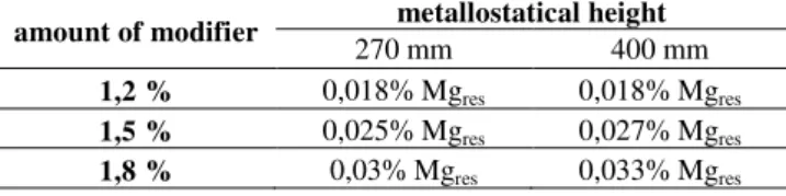
Table 2.
Influence of metallostatical height and amount of modifier on the residual values of magnesium in laboratory conditions
amount of modifier metallostatical height
270 mm 400 mm
1,2 % 0,018% Mgres 0,018% Mgres
1,5 % 0,025% Mgres 0,027% Mgres
1,8 % 0,03% Mgres 0,033% Mgres
4. Experimental section - operating
conditions
All measurements were performed in the operating conditions of foundries of cast iron with lamellar and spheroidal graphite in Czech Republic - Commercial foundry of gray and nodular iron Turnov – Foundry A and Foundry ISH Olomouc – Foundry B.
In foundry A were monitored stability and operational impacts on the dissolution of modifier such as influence of pre-heating of the reaction chamber and the length of delay between shedding of chamber on modifier consumption and thus on the final residual magnesium content in manufactured ductile iron. In foundry B was observed the differences between the production of ductile iron by FLOTRET and by sandwich method.
4.1. Modification chamber
Devices of modification chambers for all foundries were designed according to the same principles - 500 ± 100 kg. The ratios between cross-sections is used S1: S2: S3 = 3: 38: 5. The
devices are made from the steel plates of thickness 5 mm and are lined by refractory ramming masses. The cover is lined by castables and interface between the cover and the reaction chamber is thermally insulated by fibrous insulation, which also ensures tightness of the chamber against Mg vapour leakage. The cover is attaching to the chamber by four cam locks - fixed and fast connection. Bolted connections is not recommended because of the long time required for assembly and disassembly of nuts on bolts, uneven tightening of the cover around the perimeter of the chamber and uncomfortable handling with the nuts and bolts at
elevated temperatures. The chamber is placed on a pedestal,
which provides 15 ° tilt of the chamber for complete emptying of
the chamber during modification. Above the outlet is placed feeder of graphite inoculation.
4.2. Foundry A
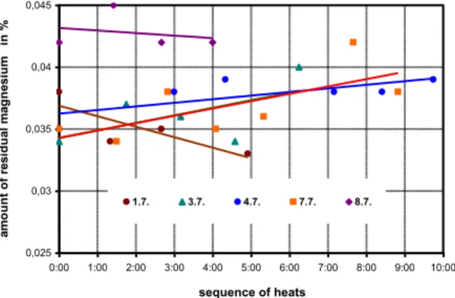
The values of residual magnesium in the period are shown graphically in Fig. 5. Values of residual magnesium related to each day of the week are in Fig. 6 and Fig. 7. The value of residual magnesium of the first modification of the day was marked as time "zero". Values are smoothed by trend line, which had a growing character for most of the days. These graphs show the effect of the temperature of the modification chamber, respectively the amount of accumulated heat in the chamber lining, on the final value of the residual magnesium.
Fig. 5. The content of residual magnesium byperiod The measured values of the delay between the shedding of modification chamber and residual magnesium are dependence which is shown in Fig. 8. Length of the delay between the individual melts, respectively shedding of modification chamber by melt, has a significant influence on the temperature of the reaction chamber and thus has an influence on the resulting value of the residual magnesium. The maximum length of the delay is circa 80 minutes according to the measured values. After this time, residual magnesium guaranteeing formation of spheroidal graphite in modified cast iron decrease into sinks to the bottom line. If this delay is longer it is necessary to ensure reheating of the modification chamber by gas burner or to shed the chamber by cast iron without modification. This fact is evident from the values Mgres on Fig. 6 for the melts made on 1.7. The delay
between the first and second modification was 1 hour 20 minutes, between the second and third was 1 hour and 20 minutes and between the third and fourth was even 2 hours 15 min and the chamber was pre-heated by gas burner only for short time before the first modification (the modification time 7:15) and the shedding of the chamber by melt was not realized. The refractory lining did not accumulate enough heat to maintain an appropriate operating temperature of the chamber.
The high utilization of magnesium from modifier, moves in real terms of foundry A around 50%, is evident from the values of residual magnesium.
0,02 0,025 0,03 0,035 0,04 0,045 0,05
0 5 10 15 20 25 30 35 40 45 heat number
a
m
o
u
n
t
o
f
re
s
id
u
a
l
m
a
g
n
e
s
iu
m
i
n
%
All the values of Mgres from the heats of cast iron with
spheroidal graphite according to ČSN 42 23 04 were accumulated
from melt records of the years 2003 till 2005. This kind of ductile iron was produced the most often, other types of ductile iron were produced in much smaller quantities. Statistical evaluation of the heats according to Mgres for the period 2003-2005 is given in
Table 3 and is graphically illustrated in Fig. 9.
Fig. 6. Change of residual magnesium content depending on time seguence of heats for each day – Week 1
Fig. 7. Change of residual magnesium content depending on time seguence of heats for each day – Week 2 Table 3.
Statistical evaluation of the heats according to residual magnesium for the period 2003-2005
year 2003 2004 2005
number of heatss 2560 2667 2979 average value of residual Mg 0,0367 % 0,0410 % 0,0426 % standard deviation 0,0057 % 0,0069 % 0,0061 %
4.3. Foundry B
This foundry produced ductile iron castings by using sandwich method, but the quality of cast iron wasn’t stable; magnesium rises to the surface, where it was burnt out. this was connected with production of dense smoke and slag and low modifier utilization. Another major drawback was a great loss of
temperature during the modification process, so that the metal in the furnace had to be overheated at higher temperatures; this was joined with the need to use more inoculants. Therefore, the main targets of the FLOTRET method were - to stabilize the modification process, to reduce a modifier consumption, to decrease overheating of the melt in the furnace, to cut the total time required for modification and to improve hygienic conditions in the workplace. Operational trials of ductile iron production were made on the melting electric induction furnace of 1000 kg. Required quality of ductile iron corresponds to the standard
ČSN 42 23 04.
In Table 4 is shown a comparison of used modifier quantity for both method of the modification. This comparison shows savings modifier 15 to 20% in favour of the FLOTRET method.
Fig. 8. The dependence of residual magnesium content on the length of delay between the melting
Fig. 9. Stability Floteret modification method in years 2003 to 2005, expressed in terms of residual values of magnesium Table 4.
Comparison of amount of modifier and inoculants for the sandwich method and FLOTRET method - Foundry B
Sandwich Bjomet 8 FeSi 75%
Modification I 300 kg 2,00 % 6,0 kg 0,80 % 2,4 kg Modification II 300 kg 2,10 % 6,3 kg 0,80 % 2,4 kg
FLOTRET Bjomet 8 FeSi 75%
Modification 500 kg 1,7 % 8,5 kg 0,50 % 2,5 kg
0,025 0,03 0,035 0,04 0,045
0:00 1:00 2:00 3:00 4:00 5:00 6:00 7:00 8:00 9:00 10:00 sequence of heats
a m o u n t o f re s id u a l m a g n e s iu m i n %
1.7. 3.7. 4.7. 7.7. 8.7.
0,025 0,03 0,035 0,04 0,045
0:00 1:00 2:00 3:00 4:00 5:00 6:00 7:00 8:00 9:00 sequence of heats
a m o u n t o f r e s id u a l m a g n e s iu m in %
10.7. 11.7. 12.7. 13.7. 14.7.
0,025 0,03 0,035 0,04 0,045
0:14 0:43 1:12 1:40 2:09 2:38
length of the delay between the individual heats
a m o u n t o f re s id u a l m a g n e s iu m i n %
first heat of the day in "zero" time
0 100 200 300 400 500 600 700 0,0 16 - 0 ,018 0,0 19 - 0 ,021 0,0 22 - 0 ,024 0,0 25 - 0 ,027 0,0 28 - 0 ,030 0,0 31 - 0 ,033 0,0 34 - 0 ,036 0,0 37 - 0 ,039 0,0 40 - 0 ,042 0,0 43 - 0 ,045 0,0 46 - 0 ,048 0,0 49 - 0 ,051 0,0 52 - 0 ,054 0,0 55 - 0 ,057 0,0 58 - 0 ,060 0,0 61 - 0 ,063 0,0 64 - 0 ,066 0,0 67 - 0 ,069
frequency intervals of residual magnesium in %
fr e q u e n c y i n te rv a ls o f n u m b e r h e a t 2003 2004 2005
total number of modification melts:
5. Conclusion
Operational trials of the FLOTRET modification method showed full functionality of modification device. Stability of the FLOTRET modification process was proved by long-term observation of the values of Mgres in foundry A. As an indicator
of stability was chosen the average value of the Mgres and it was
at the foundry A in the year 2005 Mgres = 0.0426% with standard
deviation s = 0.0061% in the range 0.020% to 0.069% Mg. The influence of delay between modifications, respectively between the shedding of the reaction chamber, on the values of residual magnesium, was also observed in foundry A. This delay should not exceed 80 minutes according to monitoring. When this time period is exceeded, there is a decrease of the chamber temperature and thus a decrease of the residual magnesium values in cast iron, as is evident from the values from 1.7. in Figure 8 - Mgres fell from 0.038% to 0.033% at otherwise identical
conditions of modification.
In foundry A was also observed the dependence of Mgres on
the sequence of the reaction chamber shedding. It was confirmed that values Mgres increase with numbers of the reaction chamber
shedding in compliance with the maximum delay between shedding (80 min). Chamber temperature increases respectively if it is maintained at operating temperature. This dependence confirms the theoretical assumptions influence of temperature on vapour pressure of Mg, i.e. as the chamber temperature is higher, the temperature of the melt is higher, the pressure of magnesium vapour generated during the dissolution of the modifier is higher and the concentration of Mgres in melt is higher. In contrast, when
the delay between modifications is overstep the temperature of reaction chamber decreases, and the value of the residual magnesium also goes down. Low temperature of the reaction chamber is also connected with the problem of rising up of the modifier from during the melt flowing through the modification device. The granular modifier is not able to dissolve enough in the chamber and then burn out in transport ladle, thereby utilization of the modifier, respectively magnesium in the modifier, goes down.
Operational trial in foundry B confirmed the saving of modifier in direct comparison of methods FLOTRET and sandwich. Modifier consumption was by the FLOTRET method about 15 to 20% lower than by sandwich method. In the case of annual production of foundry A (production in 2005 was approximately 1,500 tons of ductile iron) savings 15% would mean 4500 kg of modifier. Operational trials in all foundries were without any major complications, showed simplicity of service, low acquisition cost and low costs for operation of the device.
Based on laboratory and operational experiences the following guidelines for optimal modification process by FLOTRET were noted:
chamber has to be sufficiently pre-heated before the application, it is necessary to pre-heat the chamber again if the delay is longer (more than 80min), during shorter delay just cover with a cover.
interface between reaction chamber and cover has to be clean and fitted with gaskets to prevent the losses of magnesium vapour pressure.
clean the chamber from metal rests and slag after modification process.
compliance of chemical composition of the initial cast iron, especially the sulphur content and low content of the disturbing elements.
Operational monitoring of the chemical composition of the charge and the final modified cast iron in foundry A showed high utilization of modifier, respectively utilization of Mg from modifier, and this value is around 50%. By long-term operational monitoring in foundry A, the length of the campaign between relining of chamber linings was also traced. The average length of the campaign was 80 modifications.
Laboratory and operational trials proved the main advantages of the FLOTRET method; which are simplicity and low demands on service, low thermal losses, excellent and fast dissolving of granular modifier in the melt flowing through the reaction chamber with inoculation, and low cost for acquisition and operating of the modification device.
References
[1] http://www.trademarkia.com/flotret-73017985.html, 30.6.2009.
[2] Gedeonová, Z. & JELČ J. (2000). Metallurgy of cast irons,
Metalurgia liatin, Košice (in Slovac).
[3] Otáhal, V. (2006). Ductile Iron - Spheroidal Graphite Cast Iron. Monografie, Metal Casting and Foundry Consult,
Otahal Consult Brno, 1. vydání, Brno, p. 562.
[4] Vondrák, V., Hampl, J. & Hanus, A. (2005). Metallurgy of Cast Iron, Secondary processing of molten iron (inoculation, modification), skriptum, ES VŠB-TU Ostrava.
[5] Hanus, A. & Válek, T. (2004). Overview of the possible ways of modifying the shape of graphite. Foundry Engineering,vol. 52, no. 9, p. 388 - 389, (in Czech).
[6] Herzán, Z. (2001). Development of spheroidal graphite cast iron - basic ways of modifying. Foundry Engineering , vol. 49, no.7/8, p. 396 – 402. (in Czech).
[7] Mores, A. (2000). Methods of production of castings of spheroidal graphite cast iron in the Czech Republic. Foundry Yearbook, p. 120 – 124. (in Czech).
[8] Dawson, S. & Zhung, F. (2010). Compacted graphite iron - a material solution for modern diesel engine cylinder bloks and heads. 69. Foundry Congres Hangzhou, China, p. 359 - 364.
[9] Vondrák, V. (1988). Slévárenská ročenka 1986, Foundry
Yearbook, Brno, (in Czech).
[10]Hampl, J., Hanus, A. & Vondrák, V. (2001). Flow-continuous modification of cast iron with spheroidal graphite, in Proceedings of the Conference Cooperation
2001, Žilina (in Czech).
[11]Hampl, J., Hanus, A. & Vondrák, V. (2001). Modification of cast iron in a flow chamber, Acta Metallurgica Slovaca,
Košice, TU Košice, vol.7, pp. 146-153 (in Czech).
[12]Hanus, A. (2001). Continous modification by Flotret method.