Route Query by Sketching
Lau Bee Theng, Member, IAENG
Abstract - Route query for navigation system is frequently done
through selection that is getting a user to select two location nodes from the map. Then a route query is formulated for computation based on user’s selected nodes. Consequently users may encounter problem for selecting an origin or destination if he does not know the location name and cannot recognize it through the digital map display. Hence users may waste lots of time surveying and manipulating the digital map to obtain the locational information. A digital map consists of thousand locations for selection may make the users’ task more difficult. As a result, this research proposed a route query model that uses sketch processing model developed in Lau (2006), Lau and Wang (2002, 2003) and created a prototype for route query through real time sketching. This aims to test the possibility of applying sketching as a mode of query in navigation system. There is no real in-vehicle navigation device being tested, but it is simulated by developing software that interfaced with a sketching device for user to sketch freely. The results are obtained for the elementary testing level. More thorough researches can be conducted in future.
I. BACKGROUND
Route query is an important task in most of the navigation systems. A user could express his query using speech, text or selection, however if he has difficulties in formulating query using those modes, he would not be able to use the system. Hence a sketching mode is an enhanced feature to the query setting. This paper discusses on the implementation of an elementary sketching based route query system, the discussions cover sketching acquisition, sketch processing, route finding algorithm and testing results.
II. SKETCH PREPROCESSING
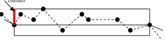
The sketch acquisition and preprocessing is the initial procedure in the prototype. In actual drawing mode, the input process captures a high-resolution line that contains both intended direction changes as well as small, unintended changes in the line's direction. Therefore simplification of stroke is an essential part that should not be neglected. The simplification of stroke implemented is based on the Principle of Douglas-Peucker Algorithm (Blaser 1998). This algorithm is used to filter significant breakpoints based on how far these points are from a generalized line shape. After the simplification of stroke, it must be actually aggregated into an object. For a new stroke, there are 3 cases distinguishing which object it may belong to that is the current object, an object other than the current one or no other previously drawn object (that is the stroke is the first of a new object). There are two factors being considered for spatial sequencing of a stroke. First is the closeness between the boundary points of the new stroke and the boundary points of a previously drawn object. Second is one of the stroke's boundary's points is close
to the edge of another object. Then a distance threshold is employed to determine if stroke belongs to the object whether to close an eventual gap, or whether to eliminate an overshoot. Segmentation is carried out to break the set of strokes of an object into non-intersecting line segments. There are four types of segments being used that is closed, self-closed, half-open, or open. To accelerate subsequent processing tasks, segments store pointers to their immediate neighbor segments. The three most common inaccuracies are inadvertently open polygons, interrupted lines and overshoots-undershoots. The prototype detects such sketch deficiencies and corrects them automatically. Then the prototype attempts to connect segments in a meaningful way with each other. Object completion is an important aspect as incomplete object may cause inaccurate retrieval.
Figure 1 Stroke Simplification (Blaser 1998)
III. ROUTE QUERY PROCESSING
Once a route finding sketch is obtained and preprocessed as in Section II, It will be processed for object matching and retrieval from large spatial database like a street maps. The sketch processing uses the SMSS model (Lau 2006, Lau and Wang 2003, Lau and Wang 2002). SMSS model consists of a spiral web structure to represent a sketch query. Section below discusses on sketch representation with spiral web structure.
Figure 2 A Sketching for Route Query
Tolerance
Engineering Letters, 13:3, EL_13_3_3 (Advance online publication: 4 November 2006)
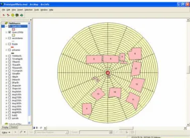
Figure 3 A Constructed Spiral Web
A spiral web is a spatial data structure that contains the data describing the sketch. The spiral web creation is determined by relative distance of reference object to the furthest object, diameter of the reference object and relative direction in a sketch’s orientation. It uses rings and zones to represent a sketch. The object value (OV) of the sketch is determined by which ring and zone it falls on. The objects in the spiral web consist of {OID, OShape, OType, OV}. For spatial fields, OID is the numerical index of every object in the spiral web; OShape is the boundary of each object exists in the spiral web in string format, and OType is the geometry type of a spiral web object in generic format that is polygon, line or point. OV is the address on the spiral web. The spatial fields required are minimal and in generic format that most spatial data files like ESRI Shapefiles can provide.
Figure 3
shows a spiral web created for the sketched query shown inFigure 2
. It has a center object marked in red with another 29 objects, the spiral web is built with 50 rings and 16 zones based on the diameter of center object that is the reference object in the sketch and the distance from center to the furthest object.Once a spiral web representation is created, OV is computed for a sketch. There are 4 computation methods for OV namely multi zones single ring (MZSR), multi zones multi rings (MZMR), single zone multi rings (SZMR) and single zone single ring (SZSR). MZSR describes object that falls into more than one zone but only one ring, MZMR describes object that falls into more than one zone and one ring, SZSR describes object that falls single zone and single ring and SZMR describes object that falls in single zone and multi rings. OV computation for MZSR is modeled in Equation 1. As there are more than a zone involve, ∑(Zone) is computed by summing up all the zones being touched by the object. Since it involves single ring, ∑(Ring) is computed by the only ring being touched by the object. RN and ZN represent the ring number and zone number of Spiral Web. RV represents the ring value and ZV represents the zone value computed for a query object. OV for MZSR is modeled in Equation 2. For more than one zones involve, ∑(Zone) is the sum of all the zones being touched by the object. On the other hand, it also
involves more than one ring, ∑(Ring) is computed by summing all the rings being touched by the object. Equation 3 shows OV computation for SZSR. Since there is one zone involve, therefore ∑(Zone) is modeled by the only one zone being touched by the object and ∑(Ring) is computed by the only ring being touched by the object. Equation 4 computes OV for an object that falls into multi zones single ring. Due to only one zone involve, therefore ∑(Zone) is computed by the only one zone being touched by the object. It involves more than one ring, so ∑(Ring) is computed by summing up all the rings being touched by the object.
Figure 4
shows a portion of the computed object values for the query inFigure 3
.[
]
[ ] ∑ ∑ = = ± = ± + + + = = 1n 1 R
1
n 1 2 n z
n n tol ] RN [ RV tol ] ZN ... ZN ZN [ ZV ) RV , ZV (
OV
(1)
[
]
[
]
∑ ∑ = = ± + + + = ± + + + = = 1n 1 2 n R
1
n 1 2 n z
n n tol ] RN ... RN RN [ RV tol ] ZN ... ZN ZN [ ZV ) RV , ZV ( OV (2) [ ] [ ] ∑ ∑ = = ± = ± = = 1 n R 1 1
n 1 z
n n tol RN RV tol ZN ZV ) RV , ZV (
OV (3)
[ ]
[
]
∑ ∑ = = ± + + + = ± = = 1n 1 2 n
1
n 1 z
n n tol ] RN ... RN RN [ RV tol ZN ZV ) RV , ZV ( OV (4)
Figure 4 Computed Object Values
IV. SKETCH SIMILARITY ASSESSMENT
For each sketch consists of a set of objects with OV, S = (S1,
S2, …, Sn), there are zero to many sets of retrieved objects
from the spatial databases, that is R={R1, R2, …, Rn}. For each
retrieved configuration, Rn there is at least more than one
retrieved object, Rn= {r1, r2, …, rn}. The similarity of a
retrieved configuration to a query, SQ is made up of a list of
assessed similarity for individual object pair, SOB where Sn is
object, N is total number of associated object pairs, SXn is the
zone value for the query object, SYn is the ring value for the
query object, RXn is the zone value for the retrieved object,
RYn is the ring value for the retrieved object, Tz is the total
number of zone exists and Tr is the total number of ring exists
in a Spiral Web. SOBJ determines the similarity of each object
in a query to a matched object from a database; hence the similarity of a query is determined by averaging the similarity values of the matched objects from database. It computes the differences with (SXi -RXj)2 that is the difference of zone
value and (SYi-RYj)2that is the difference of ring value. Equation 5 computes the structural similarity of an object in query to a retrieved object in a database. Equation 5 computes the structural similarity of an object in query to a retrieved object in a database. It computes the differences with
2 j i-RX )
(SX that is the difference of zone value and
2 j i-RY )
(SY that is the difference of ring value.
j j i i
r 2 j i
Z 2 j i j
i OB
OV R , OV S where
] T
) RY -SY ( T
) RX -(SX [ -1 ) R , (S S
← ←
+
= (5)
V. ROUTE FINDING IMPLEMENTATION
Once the retrieved destinations from spatial databases are ranked, the route processing continues. With the retrieved destination, the route from the user specified origin to to retrieved possible destinations are made utilizing Dijkstra Algorithm. In Zhan (1997), it is suggested that to obtain a one-to-one shortest path or one-to-some shortest paths, the Dijkstra algorithm offers some advantages because it can be terminated as soon as the shortest path distance to the destination node is obtained. Hence this research adopts Dijkstra Algorithm as shown in Figure 5.
begin
queue_initialization(Q);
for i=1 to n do
d(i) = + infinite;
d(s) = 0;
while (Q != Null) do
queue_removal(Q, i);
for each successor node j of node i do
if d(j) > d(i) + l(i, j) then
begin
d(j) = d(i) + l(i, j)
queue_insertion(Q, j)
end
end
Figure 5 Shortest Path Algorithm
A prototype is implemented for this research using ArcGIS Desktop V8.1 and the maps from ESRI Sample Maps. The prototype allows a user to sketch out a route query. The user has to specify his origin on the system then sketch out a spatial configuration showing the destination and its neighborhoods. The sketch is preprocessed to eliminate overshoot, undershoot, redundancy and incompleteness as shown in
Figure 1
. The object marked with an ‘X’ is the specified building that is also the user’s destination.Figure 2
shows the created spiral web for the query.Figure 4
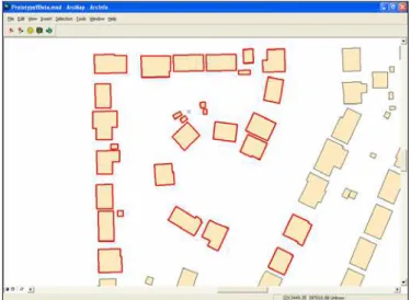
shows the extracted details of the query. With the given origin and sketch consisting the destination surroundings, the prototype system retrieved the similar building configuration from the database that is shown inFigure 6
. With the aids of the retrieved building configuration, the prototype then retrieved its parcel, primaries and secondary roads linking to the destination.Figure 7
shows the spatial database, a city map consists of roads, parcels and buildings that the query retrieves its results from. The best shortest route from origin to destination is plotted out in red bolded line.
Figure 6 Retrieved Buildings Based on the Sketch
VI. RESULTS
This research has been implemented with a set of 120 route queries. The results are shown in
Figure 8
. The results are for queries consist of 1 to 20 objects. The Spearman and Wilcoxon correlation tests indicated the correlation of the retrieval with the databases. These results indicated that the retrieval by sketching a route finding query is feasible. The retrievals have medium to high correlation with the actual routes from the road map databases.Query Set
No. of Objects
Object Type
Spearman Test
Wilcoxon Test
1 20 Polygon 0.90 0.08 2 20 Polygon 0.80 0.16 3 20 Line &
Polygon
0.79 1.08
4 20 Line & Polygon
0.76 1.10
5 20 Line 0.80 0.20
6 20 Line 0.83 0.16
Figure 8 Query Sets and Results
VII. CONCLUSION
Sketching as a route query mode in in-vehicle navigation system may suffer from incomplete sketches. However the sketch processing model used takes into account the neighborhood relations and objects geometry to produce the best route match as a resolution to the incomplete sketching. Dealing with route query in navigation system, the safety issues which cause sketching not a preferable method during driving have to be taken into consideration. In future, the research will continue to improve the prototype to take into consideration the in-vehicle navigation and driver conditions. As to date, the elementary prototype has been implemented successfully to prove the applicability of sketching for route query.
VIII. REFERENCES
[1] Blaser, A.D. (1998). Geo Spatial Sketches. Technical Report TR99-1. University of Maine: National Center of Geographic Information and Analysis.
[2] Lau, B. T. and Wang, Y. C. (2002). Spatial Query Processing for Sketch-Based Query Using Heuristics. In Proc. of 6th ICSP2002. Beijing.
[3] Lau, B. T. and Wang, Y. C. (2003). Sketch-based Spatial Query Representation and Retrieval Model. In Proc. of International Workshop on Semantic Processing of Spatial Data. Mexico.
[4] Lau, B. T. (2006). Spatial Query Retrieval by Single Measure Similarity. Dissertation for PhD in Information Technology. Universiti Malaysia Sarawak: Faculty of Computer Science and Information Technology.
[5] Lau, B. T. (2006). In Vehicle Navigation System: Visualizing Way Finding Query by Sketch. In Proceedings of 3rd ICAIET2006. Kota Kinabalu.
[6] Jun, M. (2002). Path Planning For Unmanned Aerial Vehicles in Uncertain and Adversarial Environment. In the Book Chapter of “Cooperative Control: Models, Applications and Algorithms”, Kluwer, edited by S. Butenko, R. Murphey, and P. Pardalos.