Theoretical Approach Including Friction for
Determining Strain Limits in Punch Stretching of
Anisotropic Sheet Metals
L. H. B. De Souza1, M. A. Menezes2, L. A. Moreira Filho3
1
ITA - Aeronautical Technological Institute, IEM – Praça Mal. Eduardo Gomes, 50 – Vila das Acácias – S.J.Campos, Brazil – CEP 12228-900 - [email protected] ²UNESP – São Paulo State University, Ilha Solteira Campus, DEM – Av. Brasil, 56 –
Centro – Ilha Solteira, Brazil – CEP 15385-000 - [email protected] ³ITA - Aeronautical Technological Institute, IEM – Praça Mal. Eduardo Gomes, 50 –
Vila das Acácias – S.J.Campos, Brazil – CEP 12228-900 - [email protected]
ABSTRACT: A new analytical theory including friction was developed to assess strain limits in punch stretching of anisotropic sheet metals. This new approach takes into consideration the anisotropic behaviour of sheet materials and could explain the mechanical behaviour of a variety of anisotropic sheet materials. The theory explains the sheet metal failure so for the drawing as the stretching region of the forming limit curve, particularly for materials that present the strain-ratio dependence of limit strain
ε1, where dε1/dρ is not always greater than zero. dε1/dρ or dε1/dε2 could be equal to or smaller than zero
for a range of materials. Therefore, this new theory can explains such experimental observations, besides to assuming that membrane element relations near the pole, for the case of punch stretching are dependent of sheet metal properties as the process history and also suggests that the onset of local necking is controlled by shear. Thus, theoretical results obtained through this new approach are compared with experimental results available in the literature. It is demonstrated the effect of friction on a FLC curve for both regions, drawing and stretching.
KEYWORDS: Sheet metal forming, punch stretching, strain limits, anisotropy, plastic instability and friction
PACS: 81.20.Hy
INTRODUCTION
Predicting a failure in the manufacturing process of thin sheets is not easy task. In forming limit analysis, Keeler and Backofen [1] made the first attempt to produce forming limit curves (FLCs). Goodwin [2] presented the standard form of FLCs. Extensive experimental investigation have been made to construct the FLCs of various sheet metals since Hecker [3] developed a method to obtaining a large variation of minor strains. Theoretical calculations of the forming limit have also been attempted. Prediction of the forming limit has utilized Hill’s criterion [4, 5] for diffuse and localized necking. Marciniak & Kuczynski [6] have developed a quantitative model to predict localized necking, even under biaxial stretching conditions, by considering the behaviour of an initial imperfection. Differently, St ren & Rice [7] used the plastic
443
CP1315, International Conference on Advances in Materials and Processing Technologies (AMPT2010) Edited by F. Chinesta, Y. Chastel, and M. El Mansori
deformation theory to predict the localized necking under biaxial stretching conditions.
Nowadays, the FLCs, not yet universally adopted although well established, have contributed to the development of sheet metal forming operations. So, the FLC of a sheet material defines the maximum capacity of the material when submitted to a stretching or drawing processes. Keeler and Backofen [1] have also concluded that a practical control of punch stretching limits should be based mainly upon control of uniformity of strain distribution. However, the formability of sheet metals depends not only on the properties of material, but also on the friction in the tooling/workpiece interface.
In this paper, it is analyzed the influence of material properties (i.e. the strain-hardening exponent and anisotropy) and the friction conditions in the punch stretching process, on strain limits based in the occurrence of a diffuse necking .
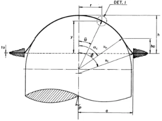
ANALYTICAL THEORY
FIGURE 1: Analysis model
Where:
RP = punch radius φ = stretching angle;
h0 = displacement of onset contact a = die radius;
h = punch displacement RE = stretching radius;
t0 = original thickness θC = contact angle;
P = punch load θ = angle of instability point.
Equations of Principal Stresses
− − + =
θ θ θ µ σ
2 cos 1
2 2 1 2
1
sen t
pRP
and
− − − =
θ θ θ µ σ
2 cos 1
2 2 1 2
2
sen t
pRP
, (1) where µ is the coefficient of friction.
Effective Stress
Since the sheet is thin, it is considered that σ3 is approximately equal to zero
(plane stress state).
For accommodating the anisotropic behaviour, Hill [5] proposed a number of possible generalizations of the quadratic yield function, and established four simplified forms considering isotropy planar sheet metal, from following a non quadratic:
, 2 2 2 2 1 3 1 3 2 3 2 1 2 1 1 3 3 2 M M M M M M M Y N M L H G F = − − + + − − ′ + − − + − + − + − σ σ σ σ σ σ σ σ σ σ σ σ σ σ σ
where the six coefficients, F, G, H, L, M’, N characterize the anisotropy, Y is the yield stress, and M>1 to ensure the convexity.
Particularly, in the case IV, when L=M′=F=G=0; as studied by Lian et al.[8], if a value M is set, it can cause a discrepancy between the place of the predicted and experimental flow, showing that the fourth form of yield function established by Hill, is the best indicator to represent the behaviour of anisotropic sheet metal. Thus, the equation (2) shows the Case IV of generalized Hill’s criterion, considering that the material exhibits only normal anisotropy with symmetry orthogonal to the plane stress conditions, that is:
(
)
M(
)
M MR
R 1 2 1 2 1 2
1
2 + σ = + σ −σ +σ +σ (2) where σ is the yield stress in tensile tests, σ1 and σ2 are the principal stresses in the
sheet plane, R is the coefficient of anisotropy, the Hill’s exponent, M, is determined
as:M =0,86R+1,14 whenR<1, and M =2 when R>1, Bressan and Williams [9]. Substituting (1) into (2) and adopting;
, 2 cos 1 2 2 − − = θ θ θ sen C it comes,
(
)
[
]
[
(
)
]
M M M P M C R t pR R 11 1 2 1
1 2 1 + + + = µ
σ . (3)
Effective Strain Equation
Assuming that the yield function and plastic potential are identical, the law of plastic flow is associated with:
(
)
(
) (
)
(
)
(
) (
)
(
)
(
)
12 1 2 1 3 2 1 2 1 2 1 2 1 2 2 1 2 1 2 1 2 1 1 1 2 2 2 1 2 1 − + = + + − = + + + − − + − = + + + − − + M M M M M M R d d R d R d σ ε σ σ σ σ ε σ σ σ σ σ σ σ σ ε σ σ σ σ σ σ σ σ
ε , (4)
by considering the stress ratio; where σ2=xσ1, it obtains that,
(
)
(
)
( ) ε ε M M A R x 1 1 1 31
1 − −
+ + =
− , (5) Where,
(
)
(
)(
)
(
)
[
M M]
x x R R A + + − + + = 1 1 2 1 1 2 .
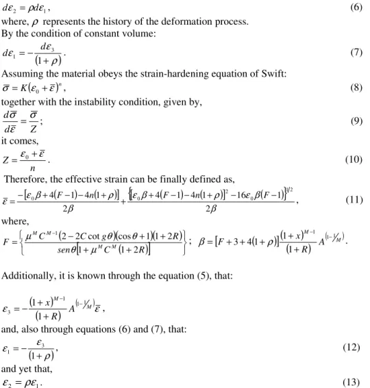
On considering the anisotropy, it follows that:
1 2 ρ ε
ε d
d = , (6) where, ρ represents the history of the deformation process.
By the condition of constant volume:
(
ρ)
ε ε + − = 1 3 1 d
d . (7) Assuming the material obeys the strain-hardening equation of Swift:
(
)
nKε ε
σ = 0+ , (8) together with the instability condition, given by,
Z d
d σ
ε σ
= ; (9) it comes,
n
Z=ε0+ε . (10)
Therefore, the effective strain can be finally defined as,
(
)
(
)
[
]
{
[
(
)
(
)
]
(
)
}
β β ε ρ β ε β ρ β ε ε 2 1 16 1 4 1 4 2 1 4 14 0 12
2 0
0 + − − + − −
+ + − − + −
= F n F n F , (11)
where,
(
)(
)(
)
(
)
[
]
+ + + + − = − R C sen R g C CF M M
M M 2 1 1 2 1 1 cos cot 2 2 1 µ θ θ θ
µ ;
[
(
)
]
(
)
(
)
( M) M
A R x
F 1 1
1 1 1 1 4 3 − − + + + + + = ρ β .
Additionally, it is known through the equation (5), that:
(
)
(
)
( ) ε ε M M A R x 1 1 1 31
1 − −
+ + −
= ,
and, also through equations (6) and (7), that:
(
ρ)
ε ε + − = 1 3
1 , (12)
and yet that,
1
2 ρε
ε = . (13)
RESULTS AND ANALYSIS
Equation (11) defines the effective strain, and so, it is possible to set the friction coefficient µ from zero (ideal lubrication) to 0,577 (sticking). For that, it is employed the experimental observations on aluminum 74750-0 carried out by Ilkiu [10], for an angle equal to 20º, a likely point of necking. Therefore, the material plastic property values employed in the construction of
ε
versusµ, and FLC curves were obtained from the literature; which are common values of typical materials used in sheet metal forming processes.Figure 2 shows the influence of the strain hardening on the prediction of effective plastic strains as a function of the friction coefficient µ. As greater is the strain hardening, greater will be the values of effective strains. Furthermore, it is
observed that when friction coefficient values increase, the effective strains decrease; chiefly for µ higher than 0.3. This fact is in agreement with previous experimental observations, where is quoted that a realistic friction coefficient value for a punch stretching process is closer to 0.2 [11].
0,0 0,1 0,2 0,3 0,4 0,5 0,6
0,2 0,4 0,6
ε
µ
n = 0,15 n = 0,25 n = 0,323 n = 0,50
R = 0,86
ε0=0,00
FIGURE 2 – The effect of the strain-hardening exponent on the effective strain.
0,0 0,1 0,2 0,3 0,4 0,5 0,6 0,2
0,4 0,6
ε
µ
ε
0 = 0,00
ε0 = 0,01
ε
0 = 0,05
ε
0 = 0,10
R = 0,86 n = 0,323
FIGURE 3 – The effect of the initial strain-hardening on the effective strain.
Figure 3, for the same material, shows the influence of the initial hardening on the prediction of effective plastic strains as a function of the friction coefficient µ. It can be seen that εo also has a significant effect on the values of effective strains, where
the increasing of initial strain-hardening of sheets reduces the deformation capacity of the sheet before failure.
Figure 4, shows the influence of the yielding criterion employed through this new approach on the prediction of effective plastic strains as a function of the friction coefficient µ. For that, it was used Von Mises, Hill 1952 and Hill 1979 criteria.
0,0 0,1 0,2 0,3 0,4 0,5 0,6 0,2
0,3 0,4 0,5 0,6
ε
µ
Current theory Hill 1952 Von Mises Experimental Aluminum 7475-0
R=0,86 n=0,323
ε0=0,00
FIGURE 4 – The effect of yielding criteria on the effective strain. Experimental points from
Ilkiu [8].
-0,4 -0,3 -0,2 -0,1 0,0 0,1 0,2 0,3 0,2
0,4 0,6 0,8 1,0 1,2
ε 1
ε 2
µ=0 µ=0,2
µ=0,3
µ=0,4 Experimental Points
Aluminum 2036 - T4
R=0,77 n=0,17
εο=0,00
FIGURE 5 – FLC for the aluminum 2063-T4. Experimental points from Gosh [10].
When comparisons are made among all yielding criteria employed through the present theory and experimental points, it can be seen a quite good agreement between them; particularly for a friction coefficient value between µ=0.0 e µ=0.2; what is according to previous experimental results. It is also clear that the best agreement between theoretical results and experimental points occurs when the present theory encompasses Hill 1979 criterion.
Additionally, Figure 5 presents a FLC curve of a common material used in sheet metal forming, where is demonstrated the adequacy of the present theory. Again, it can be seen a quite good agreement between theoretical results and experimental points, when the present theory encompasses Hill 1979 criterion and the friction coefficient value is closer to µ=0.3.
Furthermore, the theory explains the sheet metal failure so for the drawing as the stretching region of the forming limit curve, particularly for materials that present the strain-ratio dependence of limit strain ε1, where dε1/dρ is not always greater than
zero. dε1/dρ or dε1/dε2 could be equal to or smaller than zero for a range of materials.
Such characteristics are presented on sheets with n and εo values greater than
conventional values, and it would characterize the geometric softening of the sheet metal with a hard hardening, as discussed by Itikava [12].
CONCLUSIONS
The paper shows the influence of strain-hardening, initial strain-hardening and yielding criteria employed through the present theory on the prediction of effective plastic strains, as a function of the friction. It is also showed the adequacy of the theory developed based on a FLC curve. In general, the strain limits established by the proposed theory are in good agreement with the experimental results obtained from the literature for the anisotropic sheet metal analyzed, either for the region of drawing or stretching.
ACKNOWLEDGMENTS
The authors would like to thank CNPq (Brazilian National Research Council), ITA (Technological Institute of Aeronautics) and UNESP (São Paulo State University), for the financial support and for funding the research, as the support during the preparation of this work.
REFERENCES
[1] S.P. Keeler, W.A. Backofen, Trans. Am Soc. Met. 56 (1963) 25-48. [2] G.M. Goodwin, SAE Techinical paper No. 680093, 1968.
[3] S.S. Hecker, Sheet Met. Ind. 52 (1975) 671-676. [4] R. Hill, J. Mech Phys. Solids 1 (1952) 19-30. [5] R. Hill, Mat. Proc. Camb. Soc. (1979) 179-191.
[6] Z. Marciniak, K. Kuczynski, Ind. J. Mech. Sci.. 9 (1967) 609-620. [7] S. St ren, J.R. Rice, J. Mech. Phys. Solids 23 (1975) 421-441. [8] Lian, J., Barlat, F. & Baudelet, B. Int. J. of Plasticity, 5 (1989) 131-147. [9] Bressan, J. D. & Williams, J. A. Int. J. Mech. Sci., 25 (1983) 155-168. [10] Ilkiu, A.M., M. Sc. Thesis – ITA, 1992.
[11] Ghosh, A. K., Int. J. Mech. Sci., 19 (1977) 457-470. [12] Itikava, R. K., M. Sc. Thesis – UNESP/FEIS, 2002. [13] A.K. Ghosh, Met. Trans. (1976) 523-533.