STOCHASTIC FIELD PROCESSES IN THE MATHEMATICAL MODELLINC OF DAMPED TRANSMISSION._LINE VIBRATIONS
P. HAGEWRN*, .I. SCHMIDT* and N. NASCINENTO**
l
zyxwvutsrqponmlkjihgfedcbaZYXWVUTSRQPONMLKJIHGFEDCBA
Institut
fiir
Mechanik, TH Darmstadt HochschulstraDe 1, 6100 Darmstadt, Germany** Faculcade de Engenharia Guaratingueta, UNESP Av. Ariberto P. Cunha, Guaratingueta, Brazil
Abstract. Wind-excited vibrations in the frequency range of IO to 50 Hz due to vortex shedding often cause fatigue failures 1” the cables of overhead transmission lines. Damping devices, such as the Stockbridge dampers, have been in use for a long time for supressing these vibrations. The dampers are conveniently modelled by means of their driving point impedance, measured in the lab over the frequency range under consideration. The cables can be modelled as strings with additional small bending stiffness. The main problem in modelling the vibrations does however lay in the aerodynamic forces, which usually are approximated by the forces acting on a rigid cylinder in planar flow. In the present paper, the wind forces are represented by stochastic processes with arbitrary crosscorrelation in space; the case of a Karman vortex street on a rigid cylinder in planar flow is contained as a limit case in this approach. The authors believe that this new view of the problem may yield useful results, particularly also concerning the reliability of the lines and the probability of fatigue damages.
Keywords. Stochastic processes, transmission lines, vibrations
INTRODUCTION
Different vibration phenomena due to aerodynamic forces occur in overhead transmission lines. In the present paper, we only deal with vibrations
caused by vortex shedding, which can often be
observed in the frequency range of 10 to 50 Hz. Vibrations of the “galloping” type, which are of much lower frequency, are not considered.
Since approximately 1930 dampers
zyxwvutsrqponmlkjihgfedcbaZYXWVUTSRQPONMLKJIHGFEDCBA
of, the Stock-bridge type or of similar construction have been
used successfully for the supression of these
vibrations, in previous papers we have studied the optimal tuning of the dampers and estimated the
bending strains in the cable (Hagedorn, 1980,
1982). The weakest point in these and in similar calculations lies in the model of the wind forces, which are usually assumed as in a Kbrman vortex street.
Moreover,
they are assumed all in phase with the local displacement of the cable section, and this leads to contradictions, as was shown by Schafer (1984) and also explained by Hagedorn (1985a).In the present paper, a different model is used for the wind forces: they are modelled by means of stochastic field processes. In this manner, the main physical properties of a vortex street can still be maintained, but the flow is no longer assumed to be planar. It is known, that even in careful laboratory experiments the vortices shed by a cylinder at relative axial distances of the order of a few diameters are not in phase but are almost ““correlated, u”leSs special precautions are taken. This fact can easily be included in the stochastic model by considering an appropriate crosscorrelation of the excitation process.
The final goal is of course to estimate the useful lifetime of the cables of a line, depending on the
local wheather conditions and
devices used.
on the damping If such estimates were available, the utility operating the line could for example evaluate .if additional costs related to sophisti-
cated damping devices is or not economical. At the moment, the necessary data on the wind forces is not at hand, so that these calculations can not be carried out completely. The authors do however believe that the stochastic model here presented for the wind forces will be helpful in future calculations of transmission line vibrations.
THE MECHANICAL MODEL AND THE EXCITATION In a typical transmission line the span is of the order of a few hundred meters, while the sag is of a few percent of the span only. The wavelengths of the vibrations under consideration being small compared to the span, the sag can be completely disregarded in first approximation and the cable can conveniently be represented by a beam under a high tensile force. Although the cable vibrations are not strictly planar they occur predominantly in a vertical plane. In what follows, we consider a single cable under steady transverse wind oscil- lating purely in the vertical plane, described by the differential equation
EI w”“(x,t) - T w”(x,t) + m ij(x,t)
= q(x,t) + d(w,P,t) . (1)
I” (I), w(x,t) is the transverse displacement at the location x of the cable and at time t (see Fig. l), m is the mass per unrt length, q (x,t) represents the forces acting on the cable due to the wind loading and vortex shedding and d (w,w,t) stands
for
the cable’s self damping.t zyxwvutsrqponmlkjihgfedcbaZYXWVUTSRQPONMLKJIHGFEDCBA
X IrFIG. 1. Overhead transmission line with damper
360
zyxwvutsrqponmlkjihgfedcbaZYXWVUTSRQPONMLKJIHGFEDCBA
5th ICMM
The primes indicate differentiation with respect to x, while the dots stand for differentiation
with respect to t. Equation (1) is valid for
xf 1
;
at this point the damper force has to be taken ‘into account. The equation has to be solved for the boundary conditionsw (0,t) = 0, w (l,t) : 0,
(2) w’(O,t) = 0, w’(l,t) = 0,
which means that the suspension clamps are assumed as fixed during the vibrations. This is not neces- sarily so during the actual vibrations, but it certainly is a case which may occur in reality
(due
to
symmetric
spans
for
example)
and it
is
therefore
taken
as
a reference
in
the
calcula-
tions.
Only single
cables
will
be treated
in this
paper
and the case
of bundled
conductors
will
be
omitted.
As
shown in Hagedorn (1980),
the bending
stiffness
in cables
is
very
small,
i.
e.
EI/Tl* << 1, sothat the bending stiffness EI
in
(1)
can
be
omitted
in
the
calculation
of
the
vibration
levels.
This considerably simplifies the problem, since the order of the differential equation is reduced (of course the boundary conditionsin w’
are dropped
in this
part
of the calculation).
Thebending strains - which are responsible for
material fatigue - can be calculated a posteriori. The maximum bending strains - which are propor- tional to the curvature - occur at the suspension clamps at the ends of the cable and at the damper clamp, and they can be calculated by means of simple formulae from the values of w’ obtained for the string, i. e. with EI : 0, using singular per-
turbations. At x = 0, for example
in
first
approximation
the curvature
is
tPEI(O,t) = (T/EI) .;lCO: t), (3)
where the index zero refers to the string with zero bending stiffness and the index EI to the beam (see Hagedorn, 1980).
We will calculate the system’s regponse using
Green’s function (Nascimento, 1984).
For
the
string without damper, this function is easily obtained from the steady state solution of
- T w”(x,t) - + m i(x,t) + d c(x,t) = S(x-y) e jut i4) y (O,t) = 0, r (l,t) = 0,
which is of course complex (here and in what
follows we underline complex quantities); it is of the form
w (x,t) = E (y,x,w) ejWt, 15,
where H(y,x,w) is the frequency response for the damped string. In (41, linear external damping was assumed for the cable and this equation describes the problem of the vibrations of a damped string,
forced by a concentrated unit force acting at
x = y with angular frequency
.
Separation of variables leads to
H”(y,x,w) + (Ill,* - jwd) +H(y,x,w) = - f 6(x-y) (6)
and tJ(y,x,w) is given by
zyxwvutsrqponmlkjihgfedcbaZYXWVUTSRQPONMLKJIHGFEDCBA
0
( x < y ,H(y,x,w):=
1
&
ejax +
It2
zyxwvutsrqponmlkjihgfedcbaZYXWVUTSRQPONMLKJIHGFEDCBA
e-jax,
$,
zyxwvutsrqponmlkjihgfedcbaZYXWVUTSRQPONMLKJIHGFEDCBA
ejax
+ %
e-jax, y < x(1
,(‘I
(‘3)
and the A.
-1’ i q 1,2,3,4 are obtained from
H(y,O,w)
= 0 ,
fi0,J.w)
= 0 ,
X(Y,Y_ ,w) = H(Y,Y+, w ) ,
tJ’(y,y-,w) - fl’(y,y+,w) c -l/T .
(9)
The coefficients
Kit
i = 1,2,3,4
are functions
of
y and W
,
and theprime
in
(6)
and (9)
again
denotes
differentiation
with
respect
to
X.
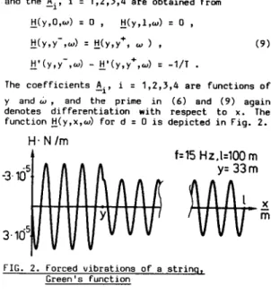
The function i(y,x,w) for d = 0 is depictedin Fig.
2.
H.N/m
f=15 Hz.l=lOO m
y- 33m
x
m
FIG. 2.
Forced vibrations of a strinq, Green’s functionFor the
computation
of
the vibrations
of a cable
with
Stockbridge
damper we do however
need
the
frequency
response
not only for the cable,
but for
the
cable
including
the
damper.
For
the
calcu-
lation
of
this
function,
consider
the cable
with
damper of
Fig.
1, executing
steady
state
forced
vibrations
excited
by a concentrated
force
2 e jwt
with frequency
w acting
at x = y.
If
the damper
force in these steady stateoscil-
lations
is
&e
jut
,
then
due
to
linearity
the
steady
state
solution
w(r,tf
can be written
as
w(x,t) = [tJY,,X’W)& +H(y,x&]
P ,
(IO)
the damper being located at Y = y,. Suppose now that the damper impedance I(w) is known, then one has
8 = - +J)$(y,) ,
1
(11)where
icy,)
is
the
complex
velocity
amplitude at x 5 y ,. Substitutingw(x,t) = p(x) ejwt (12)
in (IO) and using icy,)
= jwg(y,)
in (11) gives
6, = - L(w)jw
[!!(Y,,Y~+JE,
+
H(Y,Y,&~]
and
therefore
6, = - j I(w)
zyxwvutsrqponmlkjihgfedcbaZYXWVUTSRQPONMLKJIHGFEDCBA
1 + j
H(Y,YqW)~Wtj(y,,y,,d
’
and
w(x,t) = [ $y,x,w) -
jwl(
W))l(Y,Y,,W)
H(y ,x,w)]fi
ejwt
1 + jw~(w)~(y,,y,,w)
-
1
or
r(x,t)
= H+(y,x,w)~
ejwt
,
H+(y,x,w)
= tJ(y,x,w)
-
.@LJ$y,y,,W)
1 + jwL(w)H(y,,y,,w)
-
H(Y, ,w,w)
(13)
(14)
(15)
(16)
STOCHASTIC FIELD PROCESSES
361
The function H+,(y,x,w) is exactly the frequency response for the cable with Stockbridge damper, i. e. it gives the cable’s complex vibration amplitu- de at the location x for a unit exciting force with angular frequency w at the location y,. a damper with impedance z(w) being attached to the cable at the location y,(the argument y., ,is considered as a parameter only since it remains constant in most of the following calculations).
s(y,x,w)
is shown in Fig.3.
ItioI.
N/m
zyxwvutsrqponmlkjihgfedcbaZYXWVUTSRQPONMLKJIHGFEDCBA
II
2
Tr
_-
2
f=15 Hz, L=lOO m
)4=1.35m ,y=33 m
w
zyxwvutsrqponmlkjihgfedcbaZYXWVUTSRQPONMLKJIHGFEDCBA
X
I
ii=i
zyxwvutsrqponmlkjihgfedcbaZYXWVUTSRQPONMLKJIHGFEDCBA
FIG. 3. Green’s
Function for the cable with damperSuppose now
that in (1) an arbitrary distributed Force q(x,t) acts on the cable. If Q(x,w) is the Fourier transform of q(x,t), i. e.q(x,t) - O(x,w) , (18)
then the Fourier transform of the corresponding solution w(x,t) is
1
l$x,w) = H+o(y,x,w) (I(y,w) dy (19)
0
and w(x,t) can easily be obtained as
m
w(x,t.) =
&
I
zyxwvutsrqponmlkjihgfedcbaZYXWVUTSRQPONMLKJIHGFEDCBA
Lj(x,de@
dw-In
m
zyxwvutsrqponmlkjihgfedcbaZYXWVUTSRQPONMLKJIHGFEDCBA
1
I--
n
J
Re&(x,w)ejwt]dw, (20)zyxwvutsrqponmlkjihgfedcbaZYXWVUTSRQPONMLKJIHGFEDCBA
0
since W(x,w) is the Fourier transform of a real function. On the other hand, if h(y,x,t) is the response at the location x and at time t to a unit impulse at t :: 0 at the location y, i. e. if
h(y,x,t) ..+ H+,(y,x,w) (21)
then w(x,t) can be obtained directly in the
time
domain as
1
m
w(x,t)
=
JI
h(y,x,t)q(y,t-f)dE
dy
.
(22)yro tz-m
In the present paper however we wish to model the
wind
forces by means of an ergodic Field process q(x,t), which is completely characterized by its mean value1 E
[q(x,t)]
= m (x1:=
4 lim T...a -l 2T q(x,t) dt (23) -T
and its crosscorrelation function
E [q(y,t)q(x,c)]= k&y+, T ):=
1
=
:2P
J
q(y,t)q(x,t
+T1
dt
-T(24)
with t := E-t, For 0 s x,y ( 1 provided the process is Gaussian.
The spectral-power-density
hQ(y,x,w)
can be used instead
of k (y,x,r)
0
to characterize
the exciting
process,
it
is related
to the cross-
correlation
through
kD(y,x,
1)
-. %(y,x,w)
.
(251For a known spectral-density %(y,x,w) of the
wind
forces
and known Frequency
response
H+,(y,x,
w ) of
the
cable
with
damper,
the
cross-power-density
&w(y,x,w)
of
the
response
process
w(x,t)
can be
obtained
(Nascimento,
1984) as
1 1
&w(Y,X,W) =
il
H&,x,w)
0 0
Sq(z,,z2,w)
H&,,y,w)
dz,dz2 (26)(the
asterisk
means
“complex
conjugate”).
The
correlation
between
the
processes
w(x,t)
and
w(y,t)
is then
m
mW(x,y) = 4
J
Re [ ~+,w(x,y,w)] dw (27)zyxwvutsrqponmlkjihgfedcbaZYXWVUTSRQPONMLKJIHGFEDCBA
0
and the
variance
of
the
displacement
at
the
location
x is
0;(x)
= mW(x,x) .
(28)
In transmission
line
vibrations
we are however not
so much interested
in the displacement
amplitude,
but more in the strain
amplitudes,
since
these are
directly
related
to
the
material
fatigue.
As
explained
previously,
the bending
strains
can only
be calculated
if
the bending
stiffness
is
taken
into
account
in
the
mathematical
model
of
the
cable,
which
was not
the
case
in the
Frequency
response calculated with (6). An
excellent
appro-
ximation
to
the bending strain ishowever given by
C = g L&(0:
t) : g & w;(O+,t)
(29)
with D as the cable’s
diameters
(compare
(311,
so
that
the variance
of w’(O,t)
in the string
can be
used as a measure.For
the variance
of the bending
strains
at the suspension
clamp at x : 0.
It can
be calculated
according
to
mi i
hit = ;J
J JRe [s*(z,,~,i
0 0 0
-2
S&,z2,w)H$z2,0,
-1
) dz,dz,dw, 00)
where the prime stands For differentiation with respect to the second argument of HC.,.,.).
As shown by Nascimento (1984) the crosscorrelation Function kQ(x,y,T) of the excitation process has to satisfy certain conditions which are automati- cally Fullfilled if it is of the form
kQ(x,y,r) = F(x)F(y)k(r) +m exp
2
[_yq
362
5th
ICMM
where f(x) is an arbitrary function representing the intensity of the process, k(r) is an auto- correlation function of a suitable scalar process and p has the meaning of coefficient representing the correlation in space.
It
was
shown (Hagedorn and Nascimento, 1985) that this coefficient can have an important influence on the system's response in general and Nascimento (1984) considered different types of functions f(x).In
the
present case of transmission lines the field of the aerodynamic forces can probably be considered as homogeneous in space, so that we setf(x):= B = const. (32)
Instead of specifying directly k(r), it will be more convenient to specify its Fourier transform S(w). In the usual, deterministic model of trans- mission line vibrations the exciting forces are due to vortex shedding, so that in a realistic stochastic model the power density s(w) for a constant transverse wind velocity will be that of a narrow band process; for simplicity one can assume a spectral density as shown in Fig. 4.
FIG.
4.
Input spectral power density S(w)Its central frequency is chosen as the Strouhal frequency
w C = 2XfC -_ 2n 0.2$
D being the cable's diameter and v the wind speed, and the bandwidth 2Aw is probably of the order of a few percent of WC. Since the intensity of the wind forces can be represented by the constant B in (32), z(w) can always be normalized so that
+m
I
S(w)
dw- 1.--m
Estimates of B can be obtained from the experi- ments carried out with rigid cylinders in planar flow (see Staubli, 1983, Farquharson and MC Hugh, 1956), by comparing the power of the stochastic process to the power measured (for the maximal amplitudes) in the experiments. Little data is available on the correlation coefficient p, it is however expected that it is of the order of a few cable diameters only.
If
these parameters are known for a certain wind speed, thevariance
of w' can be computed, and due to the assumptions men- tioned the calculations simplify to the evalua- tion ofexP[ ~2-jt$(r2,0,w) dz2dz,]5(w) dw. (34)
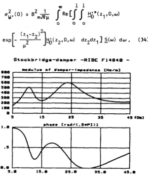
StockbrIdge-d8mper
zyxwvutsrqponmlkjihgfedcbaZYXWVUTSRQPONMLKJIHGFEDCBA
-RIBE F14848 -FIG.
5.
Impedance of Stockbridqe damperTHE SYSTEM'S RESPONSE, CONCLUSIONS
Calculations were performed for a damper of the type RIBE F14840 located at y., : 1.35 m with impe-
dance as given in Fig. 5 and a
cable
of the
Finch
type with D = 33 mm, m = 2.12 kg/m,
EI = 52 Nm*.
The span was 1 = 400 m and the tensile force T = 35 kN. The spectral density of the system's response was obtained for these data. From these results, information can also be gained on the cable's lifetime with regard to material fatigue. Details of the calculations as well as an evalua- tion of the results can be found in the paper by Schmidt and Hagedorn (1986).
The authors believe that this new view of the problem of wind-excited cable vibrations may
yield
useful results concerning the reliability of the lines and the probability of fatigue damage.
REFERENCES
Farquharson, F. 8. and R. E. MC Hugh (1956). Wind Tunnel Investigations of
Conductor
Vibration
with
Use
of
Rigid
Models.
AIEE
Transactions
Part
III
(PAS),z.Hagedorn, P. (1980). Ein einfaches Rechenmodell zur Berechnung winderregter Schwingungen an Hochspannungsleitungen mit Dlmpfern. w nieur-Archiv, 49, 161-177.
Hagedorn, P. (1982). On the Computation of Damped Wind-Excited Vibrations of Dverhead Trsnsmis-