ISSN: 1546-9239
©2013 Science Publication
doi:10.3844/ajassp.2013.1109.1114 Published Online 10 (9) 2013 (http://www.thescipub.com/ajas.toc)
Corresponding Author: Abhijeet Auti, Department of Mechanical Engineering,Symbiosis Institute of Technolgy, Symbiosis International University, Pune, India
SOLAR WATER DESALINATION
SYSTEM WITH CONDENSER WITHOUT
USING ELECTRICITY FOR RURAL AREAS
1
Abhijeet Auti,
1Tejinder Singh,
2Dilip Pangavhane and
1Ashok Chavan
1Department of Mechanical Engineering,
Symbiosis Institute of Technolgy, Symbiosis International University, Pune, India
2Department of Mechanical Engineering,Prestige Institute of Technology, RGPV University, M.P., India
Received 2013-05-23, Revised 2013-08-02; Accepted 2013-08-22
ABSTRACT
Domestic desalination is a process in which salt water is heated and converted to steam by using parabolic solar concentrator. Solar radiations incident on concentrator are focused at the absorber which contains salt water. The steam is then condensed by the condenser which is designed on the basis of the thermal analysis. Condenser is a basically a water tank with copper tubes immersed in it. The steam flows through the tubes and heat exchange takes place between steam and tank water which absorbs the heat from the steam by converting it to purified water. No electricity is used for the condensation and the equipment is suitable for a small family, having no or limited access to electricity.
Keywords: Condenser, LMTD
1. INTRODUCTION
Rural households in the coastal districts in India, suffer frequent outbreaks of jaundice, diarrhea and gastroenteritis. Some of the challenges in providing clean water in rural areas include geographic remoteness, poor maintenance of existing systems and a paucity of public funds (Carter, 2013). The two main commercial desalination technologies are those based on thermal and membrane processes (BARC, 2010). Both processes involve electricity and small domestic and household plants are not available (Mandri-Perrott, 2011). In thermal processes, saline water is heated, producing water vapour that in turn condenses to form distilled water. Most of the steam condensation techniques used water or air for cooling. Cooling can be done by circulating water or air around the steam pipe using electricity. The steam is then condensed using fluid which is circulated by pump using electricity (Kalogirou, 2005). Gude et al. (2012) have discussed desalination using solar collectors augmented by thermal energy
basically a tank filled with the water and copper tube immersed in and attached to the tank. When steam passes through the copper tubes, it gives its heat to the water and gets converted to liquid form. Continuous condensation of steam is possible without using electricity.
1.1. Selection of Concentrator
Heat generated by concentrator depends on the solar radiations, size of concentrator and reflectivity of aluminium sheet placed over the concentrator. The solar radiation, Ir was measured using optical pyranometer at
Pune, India, during the summer months and it was found to be in the range 700 to 950 Watts/m2. Average value of solar radiation in the range of 800 Watts/m2 is considered for analysis. Aluminium with reflectivity (ρ) 0.8 is used and if Ae is the effective area, then the heat
input Qi is calculated as:
i r e
Q= × × ρI A (1)
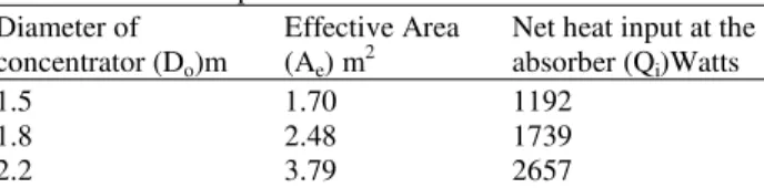
The values obtained for these three different concentrators are tabulated in Table 1 by using Equation 1.
To utilize maximum solar radiations for heating parabolic concentrator of 2.2 m diameter is manufactured (Auti, 2012) and heat utilized at the absorber, Qu is
measured experimentally.
1.2. Amount of heat Utilized
To find out the amount of steam which is generated during the heating process, it is necessary to find out the amount of heat utilized by the water. Experiments are conducted on different quantities of water. Readings of initial and final temperature of water are taken after an interval of 5 min. The time required for complete evaporation of water is also measured. The heat utilized, Qu is calculated as:
u
(Heat gain by water up to 100 C + latent heat of vaporization) Q
Time(Sec)
°
= (2)
u
initial (mass×4187×(100-T ))
+(mass×2257×1000) Q
(Time(sec)×60×60)
=
The readings are taken after every 10 min of time, for different quantities of water and the value of Qu is
calculated using Equation 2. The results are tabulated below in Table 2.
Table 1. Net heat input for different values of diameter Diameter of Effective Area Net heat input at the concentrator (Do)m (Ae) m2 absorber (Qi)Watts
1.5 1.70 1192
1.8 2.48 1739
2.2 3.79 2657
Table 2. Heat utilized for different cases
Initial temp. Time for Heat Mass of of water complete utilized water (kg) Tin (°C) evaporation(min) (Watts)
2 28 109.06 782
4 30 218.24 779
6 29 329.58 775
8 31 432.98 784
10 31 - -
The average value of heat utilized by the water is in the range of 725 to 760 Watts, so higher value of heat utilized as 790 Watts is adopted for designing the condenser. Results show that the system cannot be used for more than 8 hours in a day and from the table it is clear that maximum 8 Liters of sea water can be used for heating purpose.
1.3. Design of Condenser
Condenser designing is based on the size of condenser, required for storing water and the size of pipe containing steam, which is circulated in that water.
1.4. Size of Pipe Carrying Steam
The important task is to find out the quantity of water required for heat exchange, which indicates the requirement of size of condenser. Heat gained by the water is calculated as:
(
)
(
Qu =Qw =Mw×Cpw× Tf−Ti)
(3)where, Mw= mass of water kg/sec.
Considering temperature rise (Tf-Ti) of water by
10°C, when water gained heat from the steam, the value of Mw can be calculated from Equation 3 as:
w
790=M ×4187 10×
w
M =0.0187kg/sec
w
From above calculation it is clear that 68 Liters of water is required for each hour for removing 790 Watts of heat. The mass of water remains stationary and filled in a tank once, hence it is necessary to calculate the total quantity of water required for the entire process. For the available input, 40 min time is required for formation of steam and there after continuous formation of steam takes place. The time for which steam flows in the condenser is almost 7 h and 20 min. The total quantity of water is calculated from Equation 4 as:
w
M =70 7.33× =498.3 Liters (4)
500 liters of water is required to absorb 790 Watts of heat. If the system runs for 7 h and 20 min, then water temperature in a tank increases from 30 to 40°C. For first hour, the water required is only 70 Liters, where as 500 Liters of water is available for heat transfer. As a result of which, water temperature in the tank will not reach a value of 40° but it will be reach a temperature lesser than that and can be calculated from Equation 3 as:
f1 790=(500 / 3600) 4187 * (T× −30)
f1 1.35=(T −30)
It shows that temperature of water is increased by 1.35°C in 1 h. Similarly for the next hour, initial temperature of become 31.35°C and the final temperature is calculated as:
f2 f1
T =T +1.35 C°
Using the above equation, the water temperature in a tank reaches 40°C after 7 h.
1.5. Size of Pipe Carrying Steam
Another task is to design the pipes used in the condenser tank. Heat transfer between steam and water take place across the surface of pipes. The heat transfer across the pipe, QP is calculated by the
formula (Kreith et al., 2010):
m
p
Q = × ×U A △T (5)
where, U is overall heat transfer coefficient, whose value ranges from 1000 to 5000 W/m2K (Rathore, 2006) Lowest value of U is considered for calculating the area.
∆Tm is the log mean temperature difference which is
given by the formula Equation 6:
h,i c,o h,o c,i
h,i c,o h,o c,i
(T – T ) (T T ) T m
log((T – T ) / (T T ))
− −
=
−
△ (6)
where, Thi is the inlet temperature of steam, Tho is the
outlet temperature of steam, Tci is the initial temperature
of water, Tco is the final temperature of water. As the
water temperature increases every hour, so ∆Tm is also
calculated for each hour. Final temperature of water is 40°C, hence the final temperature of steam at the outlet of pipe, theoretically equal to 40°C. Substituting Thi =
100°C, Tho = 40°C, Tci = 30°C and Tco = 31.35°C
m (100 – 31.35) (40 30)
T
log((100 – 31.35) / (40 30))
− −
=
−
△
Substituting the value of ∆Tm is Equation 5, the area
is calculated as:
1 0.0 5
A = 259
For the next hour, Tci becomes Tco andthe value of
Tco is increased by 1.35. The values for LMTD and area
are then calculated and tabulated in Table 3.
From the result it is cleared that, maximum value of area required is 0.04662 m2. This area is the area of pipe with diameter D and Length L. Copper tube is selected as it is having more thermal conductivity. Considering standard size of pipe of 15 mm diameter, the length of the pipe can be determined as follow:
A= ∏× D×L
0.23711=3.14 0.02 L× ×
L=3.77m
Table 3. Values of LMTD and area
Hours LMTD (°C) Area (m2)
1 30.44 0.02595
2 28.41 0.02779
3 26.64 0.02964
4 24.59 0.03212
5 22.37 0.03530
6 19.90 0.03969
Considering the volume of tank is in the range of 500 liters, a tank of 1200×600×700 mm is manufactured with pipe diameter 15 mm and length 1000 mm is designed and manufactured.
2. MATERIALS AND METHODS
2.1. Experimental Analysis
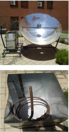
Experimental Set Up consists of solar concentrator with a black coated cooker and flexible tube attached to the copper tube in a condenser, as shown in Fig. 1.
Eight liters of salt water kept in a black coated cooker gets heated from the concentrator at around 780 watts and steam formation takes place after 40 min. One end of the flexible tube is attached to the outlet of the cooker. The steam from the cooker is passed through the copper tube via flexible tube.
Fig. 1. Experimental Set Up
Coiled shape copper tube is surrounded by the cold water which is kept in the condenser tank. Heat transfer takes place around the surface of the copper tubes and steam gets converted into water. The pure drinking water is then collected in a collector. The temperature of outlet water and tank water is measured. The same system is used for different quantities of water and outlet temperature of water is measured. Table 4 shows the outlet temperature of water for complete evaporation of particular mass of water with respect to time.
3. RESULTS AND DISCUSSION
Table 4 shows that, the outlet temprature of water by experimental analysis is lesser than the therotical value.The reason being that the tank is open to atmosphere and heat losses takes place from the tank to the surrounding. As a result, the heat which is to be absorebd by water gets reduced. The graphs are plotted to show the time of evaporation required for different quantities of water and the average outlet temperature variation with respect to time.
Table 4. Outlet temperature and time for evaporation for different quantities of water
Temperature of Outlet water after each hour (°C) --- Time for
Mass of water (kg) 1 2 3 4 5 6 7 evaporation hours
2 30.4 30.8 - - - 1.82
4 30.3 30.7 31 31.8 - - - 4.41
8 30.2 30.5 30.9 31.4 31.9 33 - 7.23
9 29.9 30.32 31.55 32.32 33.36 34.2 34.7 8.12
Average Outlet 30.2 30.58 31.15 31.84 32.63 33.6 34.7 temperature (°C)
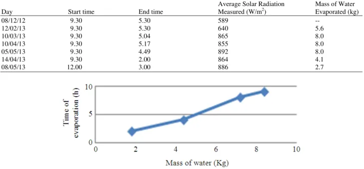
Table 5. Mass of water evaporated as per the availability of solar radiation
Average Solar Radiation Mass of Water
Day Start time End time Measured (W/m2) Evaporated (kg)
08/12/12 9.30 5.30 589 --
12/02/13 9.30 5.30 640 5.6
10/03/13 9.30 5.04 865 8.0
10/04/13 9.30 5.17 855 8.0
05/05/13 9.30 4.49 892 8.0
14/04/13 9.30 2.00 864 4.1
08/05/13 12.00 3.00 886 2.7
Fig. 3. Graph showing Mass of water evaporated as per the value of solar radiation
Other tests are conducted on 8 liters of water at different time, when solar radiations values are varying as per the month. For different values of radiations, the mass of water evaporated has changed and results are tabulated below in Table 5.
From Fig. 2, it is cleared that the time of evaporation increases with increase in the mass of water and maximum of 8 liters of water can be evaporated. The temperature in the water tank increases at faster rate at the start and then reduces. The average range of temperature remains same during each hour. Figure 3 shows that minimum value of 600 Watt/m2 radiations are required for the evaporation of water. During good sunshine condition, 8 kg of water is evaporated while during insufficient radiations the quantity of water evaporated is reduced. The quantity of water evaporation has been reduced by reducing the time for heating.
4. CONCLUSION
system works perfectly and the values of measured temperatures are almost same as that of theoretical values. The inherent limitations of natural availability of sun light, even in a tropical country like India, is perhaps the most daunting limitation in respect of this device. It also require frequent “tracking” of the parabolic concentrator which is equivalent to following the sun so as to obtain as far as possible normal incidence of its rays. It is effected by intermittent swiveling of the reflector, typically, once in 20 min or so. The absence of sun light owing any of the reasons enumerated above, may be at least partially overcome, by the use of combustible agro byproducts. These are often available in abundance at the rural locations and can be converted into combustible items. Heat may be obtained by burning these as and when required. Future work would be necessary to integrate such system with the solar concentrator.
At domestic level, such small plant can be implemented and continuous condensation of steam is possible without using electricity.
5. REFERENCES
Auti, A.B., 2012. Domestic solar water desalination system. Energy Proc., 14: 1774-1779. DOI: 10.1016/j.egypro.2011.12.1166
BARC, 2010. Desalination and Water Purification Technologies. BARC Center, Government of India. Carter, N.T., 2013. Desalination and Membrane
Technologies: Federal Research and Adoption Issues. 1st Edn., DIANE Publishing Company, ISBN-10: 1457842955, pp: 18.
Galveza, J.B., L. Garcia-Rodriguezb and I. Martin-Mateosc, 2009. Seawater desalination by an innovative solar-powered membrane distillation system: The MEDESOL project. Desalination, 246: 567-576. DOI: 10.1016/j.desal.2008.12.005
Gude, V.G., N. Nirmalakhandan, S. Deng and A. Maganti, 2012. Low temperature desalination using solar collectors augmented by thermal energy storage. Applied Energy, 91: 466-474. DOI: 10.1016/j.apenergy.2011.10.018
Joseph, J., R. Saravanan and S. Renganarayanan, 2005. Studies on a single-stage solar desalination system for domestic applications, Desalination, 173: 77-82. DOI: 10.1016/j.desal.2004.06.210
Kalogirou, S.A., 2005. Seawater desalination using renewable energy sources. Progress Energy
Combust. Sci., 31: 242-281. DOI:
10.1016/j.pecs.2005.03.001
Kreith, F., R.M. Manglik and M.S. Bohn, 2010. Principles of Heat Transfer. 1st Edn., Cengage Learning, Stamford, ISBN-10: 1439061866, pp: 696.
Mandri-Perrott, C., 2011. Social contract formulas in rural areas: The India Naandi Foundation water treatment plants. Proceedings un water International Conference, Oct. 3-5, Spain, pp: 1-9.
Rathore, M., 2006. Engineering Heat and Mass Transfer. 2nd Edn., University Science Press, New Delhi, ISBN-10: 8170088909, pp: 1152.