DOI : 10.5121/ijdps.2012.3206 67
Faiza CHARFI
1and Mohamed BOUYAHI
1
Laboratoire d’Electronique et de Technologies de l’Information Ecole Nationale d’Ingénieurs de Sfax, 3038 Sfax, Tunisie
[email protected] [email protected]
A
BSTRACTThe increasing demand for real-time applications has made the Quality of Service (Qos) support for wireless sensor networks (WSN) a fairly new research framework. In this paper, we propose an extended model of the Beacon enabled IEEE 802.15.4 including the Guaranteed Time Slot GTS allocation mechanism in the aim to analyze and evaluate network performances. Series of extensive simulations were performed to analyze the impact of the Beacon Order BO and the Superframe Order SO on the network performance based on commonly known metrics. In particular, we examine data packet delivery performance and the throughput for different duty cycle rates. Also, we analyze the impact of the number of nodes on collision probability. Thus, for high number of nodes, collision becomes higher and the reachability begins to decline slightly. We discuss and compare simulation results conducted under various parameter settings to the IEEE 802.11network.
K
EYWORDSWireless Sensor Networks (WSN), Medium Access Control (MAC), IEEE 802.15.4, Superframe Order (SO), Beacon Order (BO), Guaranteed Time Slot (GTS).
1.
I
NTRODUCTIONWith the rapid growth in wireless technologies, Wireless Sensor Networks (WSN) have become a significant research challenge, attracting research communities and industry engineers [8]. They are used in an increasing number of applications like health-care, environmental monitoring and home surveillance. The WSNs are intended to support time-critical applications which are an important class of services supported by the IEEE 802.15.4 standard. Control, actuation and monitoring are all examples of applications where the information must be delivered within some deadline.
The IEEE 802.15.4 is a standard for short range, low rate-bit and low cost wireless personal area networks. It provides MAC and PHY layers for ZigBee. The IEEE 802.15.4 MAC standard specification describes the individual node behaviour. To support time-critical applications, IEEE 802.15.4 offers a Guaranteed Time Slot GTS allocation mechanism at the network coordinator. The packets are transmitted on a superframe basis. Each superframe is divided into Contention Access Period CAP, where nodes contend among each other to send packets, and a Contention Free Period CFP, where nodes have GTSs to send packets without contention. The GTS allocation provides communication services to time critical data. It makes guarantees on packets delivery and delivery times to be transmitted to the network coordinator [12].
68 additional settings, and its performance evaluation. The proposed 802.15.4 Beacon-enabled PAN model uses a slotted CSMA/CA algorithm with GTS mechanism. We study various scenarios that arise when the nodes interact. We focus on the impact of the IEEE 802.15.4 standard parameters, specially the Beacon and Superframe orders, on packet delivery ratio, throughput and collision [6].
The paper is organized as follows: section 2 gives an overview on the IEEE 802.15.4 standard and the GTS allocation mechanism. In section 3 we discuss related work and the motivation of this paper. Section 4 presents the IEEE 802.15.4 slotted CSMA/CA algorithm. Section 5 describes both 802.15.4 MAC and PHY primitives and outlines their drawbacks. Section 6 presents the details of the experimental setup. Section 7 outlines the implementation of some primitives used by the MAC and PHY layers. A discussion on simulation results follows in section 8. Section 9 highlights the difference between ZigBee and WiFi networks. Finally, section 10 concludes the paper.
2.
O
VERVIEW ONIEEE
802.15.4
This section provides a brief overview of the IEEE 802.15.4 focusing on the relevant standard parameters to this study. The 802.15.4 is a part of the IEEE family of standards for physical and link-layers for Wireless Personal Area Networks WPANs. The IEEE 802.15.4 physical layer offers a total of 27 channels, one in the 868MHz band, ten in the 915MHz band, and finally sixteen in the 2.4GHz band [1]. The raw bit rates on these three frequency bands are respectively 20 kbps, 40 kbps and 250 kbps [11][18].
The IEEE 802.15.4 can operate either in a Beacon enabled or a non-Beacon enabled mode. The non Beacon enabled mode is useful for light traffic between the network nodes. The channel access and contention are performed using an unslotted CSMA-CA mechanism. In a Beacon-enabled network, the coordinator sends periodic Beacons containing information that allows network nodes to synchronise their communications, and information on the data pending for the different network nodes [7]. In this mode, the nodes communicate over the network through a superframe structure Figure 1. Each superframe has an active period, during which nodes can attempt to communicate using slotted CSMA/CA, and an inactive period during which devices may turn off in order to conserve energy. The active period is composed of three parts: a Beacon, a contention access period CAP and a contention free period CFP [12].
The IEEE 802.15.4 specification defines the Beacon, the MAC control, data and acknowledgment frames. All frames use a slotted CSMA/CA mechanism to access the channel except acknowledgment frames and data frame that follows the acknowledgment of a data request command, which are transmitted in the CAP.
69 Figure 1. Superframe structure with GTS reservation examples [11].
3.
R
ELATEDW
ORKSome work has been conducted in evaluating the performance of the 802.15.4 standard. In [4], the authors evoked a Beacon-enabled transmission in star networks. They study the effective compromises between power consumption and throughput or latency. They prove that small node’s duty cycle can give substantial energy savings. Also, the energy cost of synchronizing to the Beacons is significant. Author in [2] underline the suitability of 802.15.4 in wireless medical applications used in patient care applications through the network performance evaluation. Their focus is on interoperability and scalability. The study in [6] concentrates on power consumption. They determine the minimum expected power consumption in a typical WSN scenario and examine how energy is used in different phases of data transmission.
J. Zheng and M.J. Lee in [6] implemented the IEEE 802.15.4 standard on NS2 simulator and provided simulation-based performance evaluation on 802.15.4. It was a comprehensive literature that defines the 802.15.4 protocol and was mainly confined to the IEEE 802.15.4 MAC performances. This work has a minor evaluation on the performance of the peer-to-peer networks [7]. Our work here focuses on simple 1-hop star network. It describes the wireless sensor networks in the IEEE802.15.4 to integrate the GTS mechanism in the MAC layer in order to improve the Qos. To achieve this work, we chose the NS2 simulator. The Focus is on extending this simulation paradigm by introducing additional settings and performance metrics.
4.
T
HECSMA/CA
A
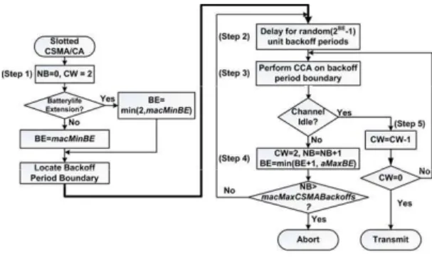
LGORITHM70 CAP duration, otherwise it waits for the next superframe’s CAP and repeats the evaluation. If the channel is busy, the MAC sublayer reinitializes the CW to 2 Backoff slots and increments both NB and BE by one (fourth step). If the NB value exceeds macMaxCSMABackoffs which is set to 5, CSMA-CA terminates with a failure status, otherwise it returns to the second step [3]. If the channel is found to be idle, the MAC sublayer decrements by one the CW (fifth step). If the latter is different from 0, the CSMA-CA returns to the third step. Otherwise, it begins the transmission in the next Backoff period. In the unslotted CSMA-CA, the transmission starts immediately if the channel is found to be idle [17].
Figure 2. IEEE 802.15.4 Slotted CSMA/CA.
5.
P
RIMITIVEMAC
ANDPHY
LAYERS OFIEEE
802.15.4
The services of a layer define the offered capabilities to ensure the information flow between the users and the layers. This information flow is modeled by discrete events, which characterizes the provision of a service primitive. The IEEE 802.15.4 standard specifies 14 PHY and 35 MAC primitives and supports two types of devices, the FFD and the RFD [8]. The FFD is a full function device supporting all the defined primitives of the standard whereas the RFD is a reduced function device. Some of these primitives are described in brief here to better understand the software implementation of the Zigbee modules.
5.1 PHY Layer primitives
The physical layer is an essential component in computer communication. It is responsible for the activation and deactivation of the radio transceiver, energy detection, link quality indication measurement, clear channel assessment, data transmission and reception. It interacts directly with the wireless channel supplying information to and from the upper layers. The PHY primitives indicate the functions organized by each layer. Whenever there is data to be transmitted, the MAC Layer Management Entity MLME calls the PHY layer with two primitives PD-DATA.request and PD-DATA.confirm to transmit a data frame. For the data packet reception, the primitive PD-DATA.indication is generated by the PHY entity and issued to its MAC sublayer entity to transfer a received PHY Service Data Unit PSDU [11].
The Clear Channel Assessment CCA is implemented by two primitives, PLME-CCA.request and PLME-CCA.confirm to identify if the channel is free or busy. The CSMA-CA algorithm invokes the PLME-CCA.request whenever an assessment of the channel is required.
71
5.2 MAC Layer primitives
The Mac layer provides an interface between upper layers and the PHY layer. It handles through its primitives various mechanisms such as Beacon Transmissions, synchronization to the Beacons, PAN Association/Disassociation, CSMA-CA for Channel Access and GTS transmissions.
Two primitives are used for data transmission from the higher layer. The MAC Common Part Sublayer MCPS-DATA.request requests the transmission of a data unit to the PHY layer. The result is indicated with the MCPS-DATA.confirm primitive as a response to successful data transmission. The MCPS-DATA.indication primitives are used for data reception from the PHY lower layer to indicate the transfer of data from the MAC sublayer to the recipient next higher layer [11].
Four types of primitives are used to provide association services: MLME-ASSOCIATE.request allows a device to request an association with a coordinator. MLME-ASSOCIATE.indication indicates the reception of an association request command; MLME-ASSOCIATE.response is used to initiate a response whereas the MLME-ASSOCIATE.confirm primitive is used to inform the initiating device of the successful or unsuccessful association.
The primitive scan is used for the detection of energy, active scan, passive scan and orphaning scan. Thus, the MAC layer performs the primitive PLME-ED.request for the energy detection. The device that has lost contact with its associated PAN sends the orphaning request for any channel for the PAN detection.
To provide GTS services three types of primitives are used: MLME-GTS.request allows a device to request a GTS to the coordinator. The GTS request is generated at the next higher layer; MLME-GTS.indication indicates the reception of a GTS request command and the MLME-GTS.confirm primitive is used to inform the initiating device of the successful or unsuccessful GTS [11].
6.
E
XPRIMENTALS
ETUP72 Figure 3. The used topology.
7.
GTS
IMPLEMENTATIONThe current implementation of the superframe structure includes the following parameters of simulation: the superframe order (SO) which manages the duration of the active period (1), Beacon order (BO) which manages the duration of the superframe (2) and the slot duration (sd) which defines the slot duration (3). aBaseSlotDuration equals 60 symbols resulting 12.5 ms whereas aBaseSuperframeDuration equals 960 symbols.
SO ion frameDurat aBaseSuper
SD= *2 (1)
BO ion frameDurat aBaseSuper
BI= *2 (2)
SO
uration aBaseSlotD
sd= *2 (3)
73 Figure 4. Result of simulation of primitive GTS.
The pan descriptor sender within the coordinator (panDes2.list[0].devAddr) represents the address of node reserved. The panDes2.list[0].slotSpec corresponds to the start slot. The panDes2.list[0].dir represents the direction of transmission. panDes2.SuperframeSpec represents the superframe specification. panDes2.list[0].length designs the length of slot reserved.
The following code is an implementation of the GTS in the Service Specific Convergence Sublayer SSCS to support GTS allocation mechanism.
\$node_(1) sscs startGTSDevice <GTSCharacteristics=0x1c> <txOption=0x02> <gtsPermit=1> <BeaconOrder=3> <SuperframeOrder=3>
channel scan
if coordinators not found association fails
elseif no coordinators permit association association fails
else
select a proper coordinator
send association request to the coord. wait for ACK
if ACK not received association fails else
send data request to the coord. wait for ACK
if ACK not received association fails else
wait for association response if asso. response not received association fails
elseif association not granted association fails
else
association succeeds send gts request to the coord. wait for ACK
74 else
wait for BCN if BCN not received gts fails else
gts succeeds
8.
S
IMULATIONR
ESULTSAn extensive series of simulations was carried out using the IEEE 802.15.4 Beacon-enabled cluster with GTS mechanism. Additional settings (BO, SO) are included to investigate their effects on the network performances. After analysing the trace file, we extract the following metrics which are used to study the performance of the proposed model of the IEEE 802.15.4. All metrics are defined with respect to MAC sublayer and PHY layer in order to isolate their effects from those of upper layers. In this work, simulation results consider Beacon order value <6. Indeed, BO= 6 and above are not suitable for wireless sensor networks because they delay excessively the node’s association time.
8.1 Throughput by node
The first experiment considers 10 nodes distributed around one coordinator. The aim is to study the throughput when different Beacon orders and different duty cycles are being set up. The throughput is calculated from the ratio of total bytes received to total time of simulation multiplied by the nodes number multiplied by one thousand (4).
1000 * _ *
_
8 * _ _
nodes number time
simulation
bytes received total
S= (4)
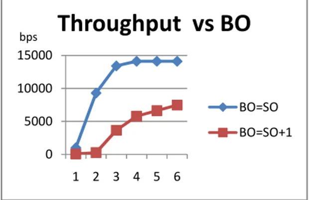
In this section, we investigate the impact of beacon order on the throughput. We assume the allocation of only one time slot GTS in each super-frame. In what follows, the change of the SO means that the beacon order also changes satisfying SO = BO. Similarly, we have made the simulation with the BO value ranging 1 from 6 Figure 5.
We remark, in the upper curve, that the closer the values of SO and BO, the more significant the throughput. However, as the inactive part increases, the throughput drops significantly. Based on the results obtained, we conclude that large inactive period can decrease throughput performance which is influenced by processing, transmitting, propagation, and queuing delays.
Figure 5. Throughput Vs BO. 0
5000 10000 15000
1 2 3 4 5 6
Throughput vs BO
BO=SO
75 As the energy savings in the beacon-enabled mode depend on the amount of periodic sleep periods introduced, it is important to control the fraction of the time that the node is active. This time, known as duty-cycle, is computed as the ratio between the superframe duration and the beacon interval that can be related to BO, SO.
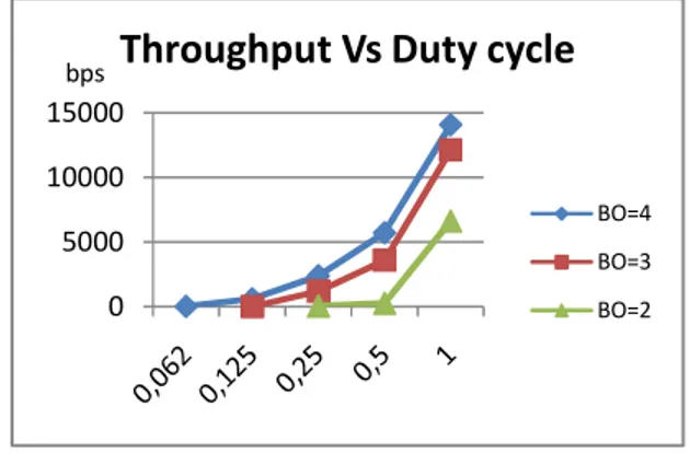
Figure 6 presents the throughput performance against varying the duty cycle by fixing BO and adapting SO to traffic. We observed that, if SO is fixed to a low value, the WSN produce lower network throughput than a higher SO value with the same duty-cycle ratio. Also, when the value of 100% duty cycle is incremented, the active period of the superframe becomes longer, which causes the increase of the transmitted packet. The scenario becomes worse with the case of inactivity period between the Beacons which result on increased amount of wasted bandwidth of an allocated GTS.
Figure 6. Throughput Vs Duty Cycle.
8.2 Packet Delivery Ratio
The second experiment evaluates the Packet Delivery Ratio which is defined by the ratio of packets successfully received to packets sent in MAC sublayer (5).
100 * _
_ _ _
packets sent
total
packets received
total
Pd= (5)
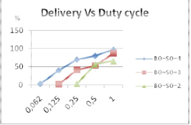
This metric does not differentiate transmissions and retransmissions, and therefore does not reflect what percentage of upper layer payload is successfully delivered, although they are related. Results from figure 7 show that lower Beacon order values such as 0, 1, 2 or 3 decrease the Packet Delivery. This is due to the fact that the node orphans too frequently, and is busy associating and re-associating itself rather than receiving data. The results become stable for Beacon order 4 and above.
0 5000 10000 15000
Throughput Vs Duty cycle
BO=4 BO=3 BO=2
The scenario becomes worse wi packets delivery ratio decreases n
Fig
8.3 Collision rate between te
Experiment 3 consists in investig nodes is varied from 5 to 15. A (BO) is varied from 0 to 6.
The total collisions that occur betw of all the packets of data removed
_ _
_ _
_
packets collision
total
packets collision
data total C=
As the number of node grows, th number of nodes will introduce the active period Figure 9. There the number of nodes and inversel
Figure 7. Delivery Vs BO.
with the case of inactivity period between the Beaco s notably Figure 8.
Figure 8. Delivery Vs Duty Cycle.
terminals
tigating the collision rate between terminals. Thus the Also, we consider only the active period and the Be
between terminals during a simulation run are defined ed to all the removed packets multiplied per hundred
100 *
ets
(6)
the percentage of the removed packets increases. Thu e a high level of collisions which decreases with the refore, we deduce that the collision percentage is pro sely proportional to the duration of the active period.
76 acons and the
the number of Beacon order
d by the ratio (6) [6].
9.
C
OMPARISON NETWORThis section compares the Beaco standards in regard to the previo by node and the Packet Delivery
9.1 Throughput by node
Figure 10 shows that the through provides significantly higher agg exploit all the band-width, but in drop in throughput can be seen in of the nodes number can ser synchronization which is due to t and packet collisions in the case
Figure
9.2 Packet Delivery Ratio
The IEEE 802.11/Wifi offers hi Beacon enabled IEEE 802.15.4 r transmitting. Indeed, the values better than the Beacon order valu
0 20 40 60 80 100 %
Figure 9. Collision Vs BO.
RKS
Z
IGB
EE ANDW
IF
Icon enabled IEEE 802.15.4 (Zigbee) and the IEEE 80 ious performance metrics for wireless networks: the ry Ratio.
ghput by node in the case of Wifi is better than ZigBe ggregate bandwidth. It is known that the Wifi netwo in the case of ZigBee the band-width is limited. Addit in both networks as the number of nodes rises. Thus, seriously degrade the network throughput by los o the increase in the number of Beacons lost in the cas
of Wifi and also Zigbee.
ure 10. Throughput Vs Number Nodes.
high Packet Delivery Ratio of 99% Figure 11. By c results in high Delivery Ratio close to that of WiFi w s of BO=5 provides a Packet Delivery Ratio of 95% lues 2 and 4.
1 2 3 4 5 6
Collision vs BO
5 nodes 11 nodes 15 nodes
77 802.11 (Wifi) he throughput
ee because it ork does not ditionally, the us, the growth loss of node ase of Zigbee
78 Figure 11. Delivery Vs Number Nodes.
10.
C
ONCLUSIONIn this paper, we focused on the modification of the IEEE 802.15.4 module into the NS2 simulator and its performance evaluation. We have extended this simulation model about Guaranteed Time Slot (GTS) mechanism supporting deterministic real-time traffic. Additional settings (BO, SO) are included to investigate their effects on the network performances. Hence, we analyzed the achieved throughput for different Beacon order values versus the number of nodes and the duty cycle. We observed that lower Beacon order gives a worse throughput because of the higher packet drop probability. Also, the growth of node number with higher Beacon order increases significantly the collision rate between the terminals and degrades the throughput due to wasted bandwidth. The IEEE 802.15.4/Zigbee using the Beacon mode achieves high Packet Delivery Ratio close to that of Wifi while active transmitting and standby period can be adjusted. Our future works will further investigate solutions to improve the performances of IEEE 802.15.4 for large scale Wireless Sensor Networks.
R
EFERENCES[1] Adel Ali Ahmed, Liza A. Latiff. & Norsheila Fisal, “real-time routing protocol with load distribution in wireless sensor network based on IEEE 802.11 and IEEE 802.15.4”, Journal Technology, Malaysia, 47(D), pp: 71-90, 2007.
[2] Changle Li Huan-Bang Li Kohno, R. State Key, “Performance Evaluation of IEEE 802.15.4 for Wireless Body Area Network”, IEEE International Conference on Workshops 2009, pp: 1-5, June 2009.
[3] R Bhakthavathsalam, “Enhancement of Throughput in 802.15.4 MAC Layer Using the Principle of Circularity”, in Novel Algorithms and Techniques In Telecommunications, Automation and Industrial Electronics, Editors: Tarek Sobh, Khaled Elleithy, Ausif Mahmood and Mohammad A. Karim, Springer 2008, ISBN 978-1-4020-8736-3.
[4] G. Lu, B. Krishnamachari, and C. Raghavendra. “Performance evaluation of the IEEE 802.15.4 MAC for low-rate low-Power Wireless Networks”, IEEE International Conference on Performance, Computing, and Communication; pp : 701 – 706, 2004.
[5] http://nile.wpi.edu/NS/.
[6] Jianliang Z. and M. J. Lee. “A comprehensive performance study of IEEE 802.15.4”, Sensor Network Operations, IEEE Press, pp: 1-14, 2004.
[7] Jianliang Z., Myung J. Lee, “Will IEEE 802.15.4 Make Ubiquitous Networking a Reality? : A Discussion on a Potential Low Power, Low Bit Rate Standard”, IEEE Communications Magazine, 42(6), pp: 140-146, June 2004.
0 20 40 60 80 100 120
5 10 20
Delivery Vs Number nodes
BO=SO=5 BO=SO=4 BO=SO=2 Wifi
79 [8] Koubaa A. “Engineering IEEE 802.15.4/ZigBee WSNs”, The First International School on
Cyber-physical and Sensor Networks Monastir, Tunisia, December 2009.
[9] Mahalik Nitaigour P., “Sensor Networks and Configuration”, Springer, ISBN-10 3-540-37364-0, pp: 31-49, 2007.
[10] Ramakrishnan S., Thyagarajan T., “Energy Efficient Medium Access Control for Wireless Sensor Networks”, IJCSNS International Journal of Computer Science and Network Security, VOL.9 No.6, pp: 273-279, 2009.
[11] ZigBee Alliance, “ZigBee Specification”, Janvier 2008.
[12] F. Charfi, O. Slama, J-M Thiriet, S. Lesecq, “Improving the control performance in Wireless Network Controlled Systems, using the Beacon mode”, Journal of Telecommunications, Vol 3, Issue1, June 2010.
[13] J. Misic, V. B. Misic and S. Shafi, “Performance of IEEE 802.15.4 Beacon-enabled PAN with Uplink Transmissions in Non-saturation Mode - Access Delay for Finite Buffers”, Proc. First International Conference on Broadband Networks”, pp: 416-425, 2004.
[14] Hui Jing and Aida, H.; “An analytical approach to optimization of throughput for IEEE 802.15.4 slotted CSMA/CA networks”, IEEE Consumer Communications and Networking Conference (CCNC), pp: 1021-1025, 2011.
[15] H. Kaaniche, F. Louati, M. Frikha, F. Kamoun, “A Qos Routing Protocol Based on Available Bandwidth Estimation for Wireless Ad hoc Networks”, International Journal of Computer Networks & Communications (IJCNC) Vol.3, No.1, January 2011.
[16] C. Kanta Samal, “TCP Performance through Simulation and Testbed in Multi-Hop Mobile Ad hoc Network”, International Journal of Computer Networks & Communications (IJCNC), Vol.2, No.4, July 2010.
[17] L. Chaari, L. Kamoun, “Performance Analysis of IEEE 802.15.4/ZigBee Standard under Real Time Constraints”, International Journal of Computer Networks & Communications (IJCNC) Vol.3, No.5, Sep 2011.
[18] Sukhvinder S. Bamber, Ajay K. Sharma, “Performance Trade off With Modulation in 802.15.4 wpan for Wireless Sensor Networks”, International Journal of Computer Networks & Communications (IJCNC) Vol.2, No.6, November 2010.