Natarajan Meghanathan, et al. (Eds): ITCS, SIP, JSE-2012, CS & IT 04, pp. 347–356, 2012.
© CS & IT-CSCP 2012 DOI : 10.5121/csit.2012.2132
Rakesh S
1, Ajitkumar A Kaller
2, Shakshari B C
3and Annappa B
4Department of Computer Science and Engineering, National Institute of Technology Karnataka, Surathkal
1
A
BSTRACTDigital watermarking is a method of copyright protection of audio, images, video and text. We propose a new robust watermarking technique based on contourlet transform and singular value decomposition. The paper also proposes a novel encryption algorithm to store a signed double matrix as an RGB image. The entropy of the watermarked image and correlation coefficient of extracted watermark image is very close to ideal values, proving the correctness of proposed algorithm. Also experimental results show resiliency of the scheme against large blurring attack like mean and gaussian filtering, linear filtering (high pass and low pass filtering) , non-linear filtering (median filtering), addition of a constant offset to the pixel values and local exchange of pixels .Thus proving the security, effectiveness and robustness of the proposed watermarking algorithm.
KEYWORDS
Image Watermarking, Contourlet Transform, singular value decomposition, Correlation, Image Entropy.
1. Introduction
348 Computer Science & Information Technology (CS & IT)
degree of directionality and anisotropy. One of the unique properties of contourlet transform is that we could have any number of directional decompositions at every level of resolutions [3]. Thus making it a one of the suitable technique for watermarking [8][9],[10].
The paper also proposes a novel method of image encryption, which is just an optional intermediate layer for multimedia data security. Also the normalized correlation coefficients (NCC) between the original watermark image and the extracted image after different attacks were calculated. The results show high improvement detection reliability using proposed method. The rest of the paper covers a brief introduction to contourlet transform and SVD in Section 2 and 3. Section 4 explains the proposed algorithm. Experimental results and conclusion are included in Section 5 and 6 respectively.
2. Contourlet Transform
It is transformation technique which is used in image analysis for capturing contours and fine details in images. The contourlet transform is composed of basic functions oriented in multiple scales at different directions with flexible aspect ratios, making it a multi resolution and multi directional transformation. This frame work forms a basis with small redundancy unlike other transform techniques in image processing. Contourlet representation contains basis elements oriented at variety of directions much more than few directions that are offered by other separable
transform technique. One way to obtain a sparseexpansion for images with smooth contours is
first apply a multistage wavelet like transform to capture the edge points, and then local directional transform to gather the nearby edge points into contour segments. With this insight, one can construct a double filter bank structure shown in figure 1(a) where the laplacian pyramidal filter is used to capture the point discontinuities, followed by a directional filter bank to link point discontinuities into linear structures. The result is an image expansion using basic elements like contour segments, and thus it is named contourlet transform.
Figure 1.Block Diagram of Contourlet Filter Bank
The directional decomposition is implemented through an l-level tree structured decomposition that leads to 2l sub bands with wedge shaped frequency partition. Fig. 2 shows the directional decomposition at every level obtained using contourlet transform. The no of directional decompositions can be chosen different and it makes this transform unique.
3. Singular Value Decomposition
Singular value decomposition (SVD) is a technique to obtain low dimensional representation for high dimensional data, which can be further processed for data compression and data de-noising.
and V are orthogonal matrices of o x N having positive elements i (
subjected to transpose, scaling, flip same as that of matrix A, making small perturbation is added to a employed for image watermarking
Figure 2
4. Proposed Algorithm
The proposed approach for wate contourlet transform and singular to ensure additional security. The
4.1. Watermark Embedding
Embedding the watermark imag camouflaged onto the original im an RGB image. This image is pr scrambled to reduce correlation. F
4.1.1. Step 1
In this step watermark image watermarked image
Step i. Apply contourlet transform
Step ii. Do the same with the wate
f order M x M and N x N, and the diagonal matrix S is (i=1,2,3,..n) called singular values. Even though the flipping, rotation or translation the singular values stil
g singular values of an image have very good stability an image, the values do not change significantly. T ing [8], [9].
2.Contourlet Transform Decomposition
termarking of still images is based on a hybrid com ar value decomposition. Also the intermediate image
e detailed steps involved are explained below.
age is a four step procedure. First the watermar image, followed by encoding the intermediate double prone to various statistical attacks, so the image is s . Further individual pixel values are encrypted to incre
e is embedded to the original image to get the
orm to the original image to decompose into sub bands
atermark image to decompose into sub bands (CTW).
is of order M he matrix A is till remain the lity i.e. when a . Thus it was
ombination of e is encrypted
ark image is ble image into s shuffled and rease entropy.
e transformed
350 Computer Science & Information Technology (CS & IT)
Step iii. Apply SVD to low frequency sub band (CTO{1}) of contourlet transformed original image.
[U S VT] = SVD(CTO{1}) (1)
Step iv. Modify matrix S so obtained, by salting it with the values of low frequency sub band of contourlet transformed watermark image.
S’ = S + CTW{1} (2)
Where being the scaling factor.
Step v. Reverse the operation in 3 to get the low frequency sub band of watermarked image.
CTT{1}=U*S’*VT (3)
Step vi. To get other of other sub bands of the watermarked image, add the corresponding sub bands of CTW to that of CTO, with the same scaling factor
CTT{i}{j}=CTO{i}{j}+ CTW{i}{j} (4)
where i=2 to 5 and j=3 if i=2 else 2^(i-1).
Step vii. Apply inverse contourlet transform using the modified coefficients (CTT) to obtain the watermarked image.
4.1.2. Step 2
The watermarked image so obtained is prone to attacks (resizing, median filtering, histogram equalization, sharpening, etc..), also as its values range from [-1000.000 +1000.000], it has to be converted to suitable format for storage and data transfer. So we propose the following novel image encryption algorithm, which results in low correlation and high entropy. Here, we convert the signed double watermarked image (IW) into an RGB unsigned 8 bit image (IW’), by the following:
If IW(x1,y1) < 0
s = sqrt(IW(x1,y1)*(-1))
else
s = sqrt(IW(x1,y1))
end
f = floor((sim-floor(sim))*100) d = floor(sim)
r = round(IW(x1,y1)-(d+f)^2)*100) IW’(x1,y1,1) = d
IW’(x1,y1,3) = r
If IW(x1,y1) < 0
IW’(x1,y1,2) = 100+f
else
IW’(x1,y1,2) = f end
indicator and later can be subtracted during decryption. Since we are considering only square root rounded to 2 decimal places, there will always be fractional error part, which is stored in blue component.
4.1.3. Step 3
Image Scrambling and Shuffling -
Step i. Divide the whole image IW’ into 16x16 size blocks, B1, B2, . . ., Bn.
Step ii. Apply Cat map within block Bi by the following equation:
= 1 1
1 2 (5)
Where (x,y) are original coordinates of IW’ and (x’,y’) are new shuffled coordinates . After repeating this step for n times we get partially shuffled image IW’’ (x, y).
Step iii. Then uniform scrambling is applied onto the image IW’’ where the pixels in the same block of original image is distributed into all the blocks of scrambled image and the every block has one pixel at least, without regarding to the order of the pixels appearance, accordingly all the pixels in the same block of scrambled image come from different blocks of original image. Figure below shows that all the pixels in the first block of the original image are distributed into all the blocks of the scrambled image. Thus, the ideal block numbers is N for an original image of size NxN. After scrambling, the resultant would be a new image IW’’’.
Figure 3. Uniform Image Scrambling
Step iv. Apply Cat map to IW’’’ to shuffle the pixels of the whole image. Steps i to iv are repeated n times to get the finally shuffled image IS. In our case we performed 3 iterations were performed to get the shuffled image.
4.1.4. Step 4
Image so shuffled is encryption to increase entropy. Encryption is performed on the image IS of size NxN using secret keys Z and L, to get the encrypted image IE using the following proposed algorithm-
for x = 1 to N for y = 1 to N
KB1=mod(10^14*Z,256) Z=L*Z*(1-Z)
352 Computer Science & Information Technology (CS & IT)
IE(x,y)= mod(IS(x,y)+KB1,256) IE(x,y)= xor(IE(x,y),KB2) end
end
In our case, the keys Z and L were taken to be 0.3915 and 3.9985 respectively. The above method uses modulus operation, restricting the encrypted values less than 256 and thus making it 8 bit encrypted image. The above steps ie., shuffling, scrambling and encryption had to be performed separately for the three RGB components of the image IW’. Also the proposed approach results in very high entropy close to the ideal value 8.
4.2. Water Mark Extraction
The encrypted image IE first has to be decrypted then the watermark image is extracted, the following three steps explain the decryption process and step 4, the watermark extraction process.
4.2.1. Step1
The image IE is decrypted by the following snippet, using the same keys Z and L used during encryption ( 0.3915 and 3.9985 respectively) -
for x = 1 to N for y = 1 to N
KB1=mod(10^14*Z,256) Z=L*Z*(1-Z)
KB2=mod(10^14*Z,256) Z=L*Z*(1-Z)
ID(x,y)= xor(IE(x,y),KB2) ID(x,y)= mod(ID(x,y)-KB1,256) end
end
The resultant would be the decrypted image ID, having the pixel values same as that of original image, but correlation between adjacent pixel still not being the same due shuffling.
4.2.2. Step 2
Now the shuffling and scrambling performed during watermark embedding process has to be nullified to get back the intermediate RGB watermarked image.
Step i. Apply inverse of the transformation matrix used in embedding process to shuffle the pixels
of the whole image. During watermark embedding, Arnold Cat transformation used 1 1
1 2 as
mapping matrix, thus here its inverse 2 −1
−1 1 is used as transformation matrix to get the
partially de-shuffled image ID’.
Step iii. The transformation matrix used in step i, is applied once again on each of the blocks B1, B2,.., Bn to de-shuffle the image block wise. Steps i to iii are repeated the same number of iterations performed during embedding process to finally remove all the shuffling and scrambling, fetching image IWD. Also the above 2 steps of de-shuffling and decrypting has to be performed separately on the RGB components of the encrypted image to get the original RGB watermarked image.
4.3.3. Step 3
Now the RGB watermarked image IWD so obtained has to be converted back to intermediate signed double watermarked image. According to the encoding algorithm, the red component of image represents decimal part of square root of required double value, green component the fractional part and blue component represents fractional error. This information is used to decode as shown by the following algorithm,
If IWD(x,y,2) >= 100 IWD’(x,y)=-1;
IWD(x,y,2)=IWD(x1,y1,2)-100; else
IWD’(x,y)=1; end
// Above takes care of sign
IWD’(x,y)=IWD’(x,y)*((IWD(x,y,1)+IWD(x,y,2)/100)^2+IWD(x,y,3))
Here x and y are pixel coordinated of the image and they range from 1 to N, since assuming IWD is of size NxNx3. Thus finally IWD’ is the decrypted watermarked image obtained, also NCC (Normalized Correlation Coefficient) between IW (watermarked image during embedding process) and IWD’ is very close to 1, proving correctness of the proposed encryption-decryption algorithm.
4.4.4. Step 4
Watermark Extraction is done by the following steps
Step i. Apply contourlet transform to the watermarked image to decompose into sub bands (CTT).
Step ii. Do the same with the original image to decompose into sub bands (CTO).
Step iii. Apply SVD to low frequency sub band (CTO{1}) of contourlet transformed original image.
[U S VT] = svd(CTO{1}) (6)
Step iv. To extract the values of low frequency sub band of contourlet transformed watermark image, originally salted during embedding we perform the following operations
S’’=inv(U)*CTT{1}*inv(VT)
CTW’{1} = (S’’ - CTO{1}) /
(7)
(8)
Here CTW’ is the extracted low frequency sub band.
Step v. Extracting the other frequency sub bands follows the following equation
CTW’{i}{j}=(CTT{i}{j}- CTO{i}{j}) / (10)
354 Computer Science & Information Technology (CS & IT)
Step vi. Finally apply inverse contourlet transform using the extracted coefficients (CTW’) to obtain the extracted watermark image.
5. Experimental Results
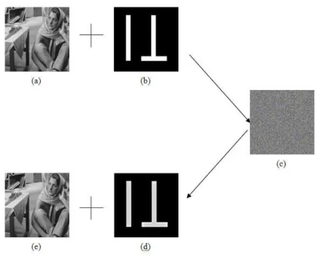
In the experiments that we have tested, we used the original image as shown in the figure(4)(a) and watermark shown in figure(4)(b). Both are gray scale images of size 512 x 512 pixels. The normalized correlation coefficient without attack is obtained to be 0.9919, which very close to ideal value 1 as shown in figure(4)(c). Also the intermediate encrypted RGB watermarked image shown in figure(4)(d) has an ideal entropy of 8, which is the required. Normalized Correlation Coefficient is calculated using the equation (11) and entropy by the equation (12). MATLAB was used for testing the robustness of the proposed approach. Various attacks that was used to test robustness of the proposed watermark algorithm are erode, dilate, open, close, const value added and subtracted, motion filter, gaussian blur, sharpening, weiner filter, high pass filter, low pass filter and mean filter. The results of the various above attacks are shown in table 1.
Entropy is calculated by the equation below
Entropy = (p(k) ∗ log(1/p(k))) (11)
where p(k) is the probability of occurrence of a pixel with gray scale value k.
And Normalized Correlation Coefficient is calculated by the equation
NCC = ( , ) ( , )
( , ) ( , )
(12)
where I is the mean centred watermark image, I’ is the extracted mean centred watermark image, and both are of size MxN
Figure 4. Step involved in Watermark Embedding and Extraction
Attack
Erode
Open
Const value added
Motion filter
Sharpening
Low pass filter
Mean filter
The proposed algorithm works w figure(5). The extracted waterma quality of extracted watermark su texture degrades as shown in the f
(a
Figure 5. (a) Original
(a)
Figure 6.Extracted Watermark
6. Conclusion
We proposed a new approach for contourlet transform and singular encryption for multi-media data information is robust and the exp large blurring by mean and Gaus
NCC Attack NCC
0.9821 Dilate 0.9627
0.9886 Close 0.9899
0.9898 Const value subtracted 0.9905
0.9893 Gaussian blur 0.9865
0.9818 Weiner filter 0.9906
0.9904 High pass filter 0.9897
0.9899
well for more complicated watermark images also, ark image has a NCC of 0.9717 which is appreciab survives after several attacks, but in some cases the e figure(6)
(a) (b)
al Watermark Image (b) Extracted Watermark Image
(b) (c) (d)
rk after (a)Erode (b) Dilate (c) Gaussian blur (d) Low p
or watermarking of still images based on a hybrid com lar value decomposition concepts, also imparting a n ta security. The proposed method of embedding th xperimental results show that it has survived various ussian filtering, linear filtering (high pass filtering a
as shown in able. Also the he quality and
d)
pass filter
356 Computer Science & Information Technology (CS & IT)
filtering), non-linear filtering (median filtering), addition of constant offset to the pixel values, local exchange of pixels and more. Future work will concentrate to extend the same to video and audio watermarking, also making the method more practical that can be implemented in real life applications.
7. References
[1] Minh N. Do, and Martin Vetterli, “The Contourlet Transform: An Efficient Directional Multiresolution Image Representation” IEEE transaction on image processing,vol 14,issue no 12,pp 2091-2106,Dec 2005.
[2] E. J. Candes and D. L. Donoho. Curvelets- a surprisingly effective nonadaptive representation for objects with edges. Saint-Malo Proceedings, 1999.
[3] Elham salahi ,M.Shahram Moin and Ahmad salahi “A new Visually Imperceptible and Robust Image water marking Scheme in contourlet Domain” International conference on intelligent information hiding and multimedia signal processing, 2008.
[4] C. T. Hsu and J. L. Wu. Multiresolution watermarking for digital images. IEEE Trans. on Circuit and Systems, 45:1097– 1101, Aug. 1998.
[5] D. Kundur and D. Hatzinakos. Towards robust logo watermarking using multiresolution image fusion principles. IEEE Trans. on Image Processing, 6(1):185–198, Feb. 2004.
[6] R. Liu and T. Tan, “An SVD based watermarking scheme for protecting rightful ownership”, IEEE Trans, Multimedia. Vol. 4 , no.1, pp.121-128, Mar. 2002.
[7] Alexander Sverdlov,Scott Dexter and Ahmet M.Eskicioglu “Robust DCT_SVD domain image watermarking for copyright protection: embedding data in all frequencies”.
[8] Akhaee, M. A.; Sahraeian, S. M. E.; Marvasti, F. (2010): Contourlet-Based Image Watermarking Using Optimum Detector in a Noisy Environment, IEEE Transactions on Image Processing, 19(4), pp. 967-980.
[9] B.Chandra Mohan and S.Srinivas Kumar “ Robust Digital watermarking scheme using Contourlet Transform” IJCSNS International journal of computer science and network security,Vol.8 No.2,February 2008.