DWESD
5, 47–65, 2012Assessing variable speed pump
efficiency
A. Marchi et al.
Title Page
Abstract Introduction
Conclusions References
Tables Figures
◭ ◮
◭ ◮
Back Close
Full Screen / Esc
Printer-friendly Version
Interactive Discussion
Discussion
P
a
per
|
Dis
cussion
P
a
per
|
Discussion
P
a
per
|
Discussio
n
P
a
per
|
Drink. Water Eng. Sci. Discuss., 5, 47–65, 2012 www.drink-water-eng-sci-discuss.net/5/47/2012/ doi:10.5194/dwesd-5-47-2012
© Author(s) 2012. CC Attribution 3.0 License.
Drinking Water
Engineering and Science
Discussions
O
p
en
Acc
e
s
s
This discussion paper is/has been under review for the journal Drinking Water Engineering and Science (DWES). Please refer to the corresponding final paper in DWES if available.
Assessing variable speed pump e
ffi
ciency
in water distribution systems
A. Marchi1, A. R. Simpson1, and N. Ertugrul2
1
School of Civil, Environmental and Mining Engineering, The University of Adelaide, SA 5005, Australia
2
School of Electrical and Electronic Engineering, The University of Adelaide, SA 5005, Australia
Received: 25 January 2012 – Accepted: 30 January 2012 – Published: 15 March 2012
Correspondence to: A. Marchi ([email protected])
DWESD
5, 47–65, 2012Assessing variable speed pump
efficiency
A. Marchi et al.
Title Page
Abstract Introduction
Conclusions References
Tables Figures
◭ ◮
◭ ◮
Back Close
Full Screen / Esc
Printer-friendly Version
Interactive Discussion
Discussion
P
a
per
|
Dis
cussion
P
a
per
|
Discussion
P
a
per
|
Discussio
n
P
a
per
|
Abstract
Energy savings and greenhouse gas emission reductions are increasingly becoming important design targets in many industrial systems where fossil fuel based electrical energy is heavily utilised. In water distribution systems (WDSs) a significant portion of operational cost is related to pumping. Recent studies have considered variable speed
5
pumps (VSPs) which aim to vary the operating point of the pump to match demand to pumping rate. Depending on the system characteristics, this approach can lead to considerable savings in operational costs. In particular, cost reductions can take ad-vantage of the demand variability and can decrease energy consumption significantly. One of the issues in using variable speed pumping systems, however, is the total effi
-10
ciency of the electric motor/pump arrangement under a given operating condition. This paper aims to provide a comprehensive discussion about the components of WDS that incorporate variable speed pumps (including electric motors, inverters and the pumps themselves) to provide an insight of ways of increasing the system efficiency and hence to reduce energy consumption. In addition, specific attention is given to selection of
15
motor types, sizing, duty cycle of pump (ratio of on-time and time period), losses due to installation and motor faults. All these factors affect the efficiency of motor drive/pump system.
1 Introduction
Attention towards efficient and eco-friendly management has been growing in recent
20
years, especially in systems characterized by a large consumption of non-renewable energy. Most water distribution systems (WDSs) require the operation of pumps to de-liver the necessary quantity of water with the adequate pressure to the final consumers. As reported by Lingireddy and Wood (1998) and Bene et al. (2010), the electrical en-ergy used to pump water is a significant portion of the total operational costs in WDSs.
25
DWESD
5, 47–65, 2012Assessing variable speed pump
efficiency
A. Marchi et al.
Title Page
Abstract Introduction
Conclusions References
Tables Figures
◭ ◮
◭ ◮
Back Close
Full Screen / Esc
Printer-friendly Version
Interactive Discussion
Discussion
P
a
per
|
Dis
cussion
P
a
per
|
Discussion
P
a
per
|
Discussio
n
P
a
per
|
In most of the cases, optimization of operations has only considered fixed speed pumps (FSPs) and the cost savings that may be obtained by exploiting a multi-pattern electric tariff(McCormick and Powell, 2003; van Zyl et al., 2004; Salomons et al., 2007; L ´opez-Ib ´a ˜nez et al., 2008; Broad et al., 2010). As a result the energy consumption by the fixed speed pump remains approximately the same.
5
As an alternative, the cost related to pump operation can be reduced by decreasing energy consumption. An attractive alternative to reach this target is the use of variable speed pumps (VSPs) instead of FSPs. VSPs are pumps coupled with a motor that is controlled by an inverter (variable speed controller). The principal duty of the inverter is to alter the mains supply to vary the speed of the motor while delivering the required
10
torque at higher efficiency. As a result, as the pump speed changes, the pump curve is adjusted for different operating conditions. The main advantages of VSPs are exploited when the operating conditions in the system are characterized by a high variability. In this case, while an FSP’s operating point is forced to remain on the pump curve for a constant pump speed, with a possible decrease in the pump efficiency, VSPs have the
15
possibility of maintaining high efficiency by effectively scaling the pump curve as the pump speed is varied.
Although good efficiencies can be maintained by considering proper options, such as using control valves or selecting the correct number and type of parallel pumps, VSPs can still be advantageous in reducing energy consumption, water losses and pipe wear
20
(Lingireddy and Wood, 1998). However, VSP convenience is not always guaranteed: manuals such as Hydraulic Institute et al. (2004) or BPMA et al. (2003) describe the WDSs characteristics for which VSP are not as attractive. In addition, prediction of the total efficiency of VSP system is not clear specifically at light loads. Although it is known that the efficiency decreases when the speed rate is reduced (Lingireddy and
25
DWESD
5, 47–65, 2012Assessing variable speed pump
efficiency
A. Marchi et al.
Title Page
Abstract Introduction
Conclusions References
Tables Figures
◭ ◮
◭ ◮
Back Close
Full Screen / Esc
Printer-friendly Version
Interactive Discussion
Discussion
P
a
per
|
Dis
cussion
P
a
per
|
Discussion
P
a
per
|
Discussio
n
P
a
per
|
The overall efficiency of VSP, called wire to water efficiency, is a result of various fac-tors since every component in the pump system has losses. In the simplified scheme shown in Fig. 1, the main difference between VSPs and FSPs is the introduction of the inverter and the absence of the valve, which have an impact on the total efficiency of the pump system.
5
This paper aims to provide a comprehensive discussion about the components of pumping systems in WDSs (inverters, electric motors and pumps) to provide insight into ways of increasing the system efficiency and hence to reduce energy consump-tion. The next section explains why VSPs can be advantageous compared to FSPs. The following sections describe the interaction between pump, motor and inverter
char-10
acteristics, and provide insights how these characteristics are modified when the pump speed rate is changed. Further discussions are also provided to assess potential motor types and motor management issues in practical systems.
2 Possibilities for energy saving in WDSs with VSPs
The energy used by a pump in a water distribution system,E (kWh), is the product of
15
the specific weight of water,γ (N m−3), the flow delivered, Q (m3s−1), the increase in
head across the pump,HP(m), and the operating timet(h) divided by the wire to water system efficiency,ηww.
The pump headHPis the sum of the static headHs, i.e. the difference in water levels between the two reservoirs, and the friction losses before and after and the pump P,
20
shown as hf2 and hf1 respectively in Fig. 2a. As the velocity head can normally be neglected in WDSs,HPis representative of the increase of energy in the flow: part of this energy will be dissipated due to the friction losses, while the remaining part will be converted from pressure to potential energy associated with the increase of elevation. The friction losseshf(the sum ofhf1andhf2) are an approximately quadratic function of 25
DWESD
5, 47–65, 2012Assessing variable speed pump
efficiency
A. Marchi et al.
Title Page
Abstract Introduction
Conclusions References
Tables Figures
◭ ◮
◭ ◮
Back Close
Full Screen / Esc
Printer-friendly Version
Interactive Discussion
Discussion
P
a
per
|
Dis
cussion
P
a
per
|
Discussion
P
a
per
|
Discussio
n
P
a
per
|
therefore the new headHP1will be smaller thanHP. Thus, the energy consumed by the new pump P1 will be smaller than the energy used by P because of the smaller flow and head.
As pumps are often sized considering the system conditions at the end of its service life, the actual operating points can be different from the design criterion. In addition,
5
the daily and seasonal variability in water demand can further move away the actual pump operating point from the expected one.
If the pump used is a fixed speed pump, the operating point is forced to move along the pump curve corresponding to the fixed nominal speed. If the system is not modified, the system curve can possibly intersect the FSP curve in a region of low efficiency. A
10
common way to avoid this drawback is the modification of the system curve by the insertion of valves. Although this leads to an increase in pump efficiency, it is a waste of energy because of the additional losses introduced by the valve.
VSPs can take advantage of the different required operating conditions in WDSs. In particular, the reduction in energy consumption exploits the possibility of reducing
15
head or flow in the system. Figure 2b shows the case in which the required flow is smaller than the actual operating point. This can be the case of a water transmission system, where pumps are used to move water from a lower to an upper tank. Since the pumping has been at a particular time of the year may be sized for a peak-day demand, the pump will deliver a flow associated with the operating point despite the fact that the
20
required demand is decreased (for example because of the seasonal variability). Given that smaller flows imply smaller friction losses, the grey area in Fig. 2b can be seen as energy wasted. However, this operating strategy can be economically convenient if the system has a sufficient storage volume so that pumps can be switched on only during the off-peak-tariffperiod.
25
DWESD
5, 47–65, 2012Assessing variable speed pump
efficiency
A. Marchi et al.
Title Page
Abstract Introduction
Conclusions References
Tables Figures
◭ ◮
◭ ◮
Back Close
Full Screen / Esc
Printer-friendly Version
Interactive Discussion
Discussion
P
a
per
|
Dis
cussion
P
a
per
|
Discussion
P
a
per
|
Discussio
n
P
a
per
|
pump, respectively. If the pump is a fixed speed pump, there is no inverter and thus ηinv may be taken as equal to 1.
ηww=ηinv·ηmot·ηpump (1)
The following section of the paper will consider the impact of changing the pump speed rate on the pump efficiency,ηpump, which will be followed by the discussions about types
5
of motors and inverters to obtain a variable speed pump system.
3 Pump operation at variable speeds
Pumps used in WDSs are often centrifugal pumps characterized by the fact that the flow-head curve remains sufficiently flat for a wide range of flows. The relationships that link the pump characteristics (flow, Q, head, H, power, P) operating at different
10
speeds (N1, N2) are described by the affinity laws: the ratio of the pump flow rates, pump heads and pump powers is a linear, quadratic and cubic function, respectively, of the pump speed ratio.
The approximation introduced in the power-speed relation implies that the efficiency will remain constant for speed N1 and N2, i.e. that the efficiency curve will be only 15
shifted to the left in case of speed reduction. Equation (2) is given by S ˆarbu and Borza (1998), which provides an analytical relationship between two different speeds (N1andN2) and the corresponding efficiencies (η1,η2).
η2=1−(1−η1)·
N
1
N2
0.1
(2)
Therefore, as indicated in S ˆarbu and Borza (1998), the changes in efficiency can be
20
DWESD
5, 47–65, 2012Assessing variable speed pump
efficiency
A. Marchi et al.
Title Page
Abstract Introduction
Conclusions References
Tables Figures
◭ ◮
◭ ◮
Back Close
Full Screen / Esc
Printer-friendly Version
Interactive Discussion
Discussion
P
a
per
|
Dis
cussion
P
a
per
|
Discussion
P
a
per
|
Discussio
n
P
a
per
|
the pump will operate with the same efficiency once inserted in the system. In fact, the operating point is defined by the intersection of the pump curve with the system curve. Figure 3 shows that, in a system with zero static head, the pump can operate with the same efficiency of the nominal speed. In contrast, when the static head of the system is a significant portion of the total head delivered by the pump, the efficiency of the
5
pump operating at a reduced speed can rapidly decrease below an acceptable level. In systems where there is a static head component, the allowable decrease in pump speed rate is limited by several factors. Firstly, the minimum pump speed rate is defined by the speed at which the shutoffhead of the pump corresponds to the static head of the system. Secondly, the efficiency of the new operating point should be evaluated
10
as it is the most restrictive condition in case of system with large static head relative to the total pump head. Finally, the speed should not be reduced beyond the 70 % of the nominal speed, so to consider that the pump maintains the same BEP. However, as it can be observed in Fig. 1, the highest efficiency in variable speed pump systems can be achieved if all the system components (included motor and inverter) have higher
15
efficiency at the operating points, which will be discussed in the following sections.
4 Motor options
Reducing losses in motors and associated motor drives can result in substantial cost savings. In fact, pump operations account for about 20 % of the total electric energy used in industry and more than 95 % of an electric motor’s life cycle cost is related to
20
energy consumption (Fuchsloch et al., 2008).
The majority of electric motors used in pump applications are induction (asyn-chronous) types as they operate directly from AC mains supply and are self starting. In addition, they are low cost machines, are reliable and have relatively high efficiency, which can be considered relatively constant if motor operates above 50 % of rated
25
DWESD
5, 47–65, 2012Assessing variable speed pump
efficiency
A. Marchi et al.
Title Page
Abstract Introduction
Conclusions References
Tables Figures
◭ ◮
◭ ◮
Back Close
Full Screen / Esc
Printer-friendly Version
Interactive Discussion
Discussion
P
a
per
|
Dis
cussion
P
a
per
|
Discussion
P
a
per
|
Discussio
n
P
a
per
|
determined by the supply frequency and can be altered by a variable speed drive, an in-verter. The operating speed range of these motors are normally between synchronous speed (no-load) and rated speed (full-load). In IMs, the ratio of the speed difference between synchronous and rated speed relative to the synchronous speed is known as slip,s. The name plate of an IM always gives a rated speed that is slightly less than
5
the synchronous speed, and such motors are designed to deliver rated torque (that is, rated output power) at rated speed. To a first approximation the torque versus speed curve of an IM can be approximated as a straight line between synchronous speed and rated speed. Although the motor characteristics can differ slightly, their efficiency varies significantly with the load and the highest possible efficiency of an induction motor
op-10
erating at a slips, is equal to 1-s. For instance at a slip=0.1, the maximum possible efficiency is 90 %. In practice the actual efficiency is somewhat lower than this due to other losses in the machine.
A detailed loss breakdown of induction motor as function of power rating has been studied in Fuchsloch et al. (2008). It was reported that typically 50 % of IM losses can
15
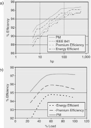
be removed by keeping the stator the same and replacing the rotor with a permanent magnet (PM) rotor, which results in a motor named brushless PM motor. These types of motors show opportunity to improve efficiency (Fig. 4a), and they generally have better low-speed and light-load efficiency (Fig. 4b) because of lack of magnetising cur-rent (which is required in induction motors). Figure 4 also illustrates that brushless PM
20
motors can provide an opportunity to extend efficiency to a level beyond that defined by National Electric Manufacturing Association (NEMA), Premium Efficiency. Further-more, brushless PM motors can provide a very high power factor (about 0.95) that is noticeable specifically at light loads (which typically vary between 0.55–0.75 at light loads in IMs) (Melfi et al., 2009). Note that the power factor indicates the effective
util-25
DWESD
5, 47–65, 2012Assessing variable speed pump
efficiency
A. Marchi et al.
Title Page
Abstract Introduction
Conclusions References
Tables Figures
◭ ◮
◭ ◮
Back Close
Full Screen / Esc
Printer-friendly Version
Interactive Discussion
Discussion
P
a
per
|
Dis
cussion
P
a
per
|
Discussion
P
a
per
|
Discussio
n
P
a
per
|
Although the brushless PM motors are more expensive than the induction motors, the purchase price of electric motor is a small part (about 3–5 %) of the total cost of op-eration (TCO). However, slight variations in their operating efficiency could dramatically affect the TCO through electricity costs (about 70 % over their lifetime).
In addition, implementation of motor management program alone can reduce the
en-5
ergy usage up to 15 %, which should consider motor installation related issues includ-ing soft-foot, misalignment, poor electrical connection, poor power factor, undersized electrical conductor as well as supply variation and supply unbalance. These can be considered as hidden faults in motor systems as they do not cause an immediate loss of operation but significantly affect the energy usage. For example, the motor set-up
10
fault, misalignment, can increase the energy consumption up to 10 %, the extra resis-tances causes the bad electrical connection (called a hot joint) can reduce efficiency 1.5 %, and 2 % of supply voltage imbalance can result in a temperature increase in the motor by 10◦C that shorten the life of insulation by half as well as cause reverse
sequence of magnetic field in IMs, which cause further reduction of the efficiency.
15
In addition, these hidden faults also directly affect the reliability of the system as they can develop severe faults in motors as they reduce bearing life, motor performance and efficiency as well as causing noise and vibration.
5 Inverters
Inverters (variable speed controllers) can simply control motor speed by varying eff
ec-20
tive voltage and frequency, which is obtained from a fixed voltage and fixed frequency three-phase mains supply. Brushless PM motors cannot operate without an inverter due to their structure. However, from a cost and complexity point of view, there is not much difference between the inverters used in IMs or brushless PM motors for the same power ratings. Although there are different types of inverters and control
25
DWESD
5, 47–65, 2012Assessing variable speed pump
efficiency
A. Marchi et al.
Title Page
Abstract Introduction
Conclusions References
Tables Figures
◭ ◮
◭ ◮
Back Close
Full Screen / Esc
Printer-friendly Version
Interactive Discussion
Discussion
P
a
per
|
Dis
cussion
P
a
per
|
Discussion
P
a
per
|
Discussio
n
P
a
per
|
There have been difficulties in estimating and measuring the efficiency of a motor (IM or brushless PM motor) controlled by an inverter (variable speed controller). Interna-tionally approved standards or testing procedures of motor/inverter combination are not available at present (Stockman et al., 2010). Since the inverter can operate the motor over a wide range of speeds, it is important to know efficiency values of inverter/motor
5
combination at each operating point to accurately determine the operating point of a pump, which is known as iso-efficiency contours. Stockman et al. (2010) have reported a successful measurement procedures how to obtain the iso-efficiency contours of in-verters connected to both IMs and brushless PM motors. It was demonstrated that the brushless PM motor has far better efficiency values compared to IM.
10
It should be noted here that in variable drive systems, there are additional losses generated in the motor by the inverter. In addition, the inverters perform rapid switch-ing of DC voltages across the motor windswitch-ings which can cause damage to the motor insulation (resulting reduced motor life) which is normally only designed for sinusoidal voltages. Therefore, in variable speed pump applications it is important to use motors
15
that have specially designed insulation to allow them to handle with inverter operation.
6 Case study
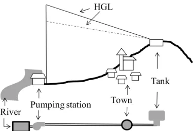
A case study is presented to show how the efficiencies of variable speed drive, motor and pump impact the VPS power. The case study consists of a pump that lifts water from a reservoir to a tank while supplying customers (Fig. 5). If the pump can be run
20
at a reduced speed, the hydraulic grade line will have a flatter slope than the one at full speed, because of the reduced flow and hence reduced head losses.
It is assumed that during the low demand periods (e.g. at night) the pump speed can be reduced to 75 % of the full speed, while still meeting the water supply requirement, i.e. the same amount of water is pumped during the day, often resulting in the VSP
25
DWESD
5, 47–65, 2012Assessing variable speed pump
efficiency
A. Marchi et al.
Title Page
Abstract Introduction
Conclusions References
Tables Figures
◭ ◮
◭ ◮
Back Close
Full Screen / Esc
Printer-friendly Version
Interactive Discussion
Discussion
P
a
per
|
Dis
cussion
P
a
per
|
Discussion
P
a
per
|
Discussio
n
P
a
per
|
The hydraulic model of the case study (lower part of Fig. 5) has been implemented in EPANET 2 (Rossman, 2000). EPANET uses the affinity laws to compute the pump characteristics at the pump reduced speed: the simulation results show that pump flow and head are 51.9 l s−1and 61.03 m, respectively. The pump e
fficiency computed using the affinity laws is 83.03 %. As a result, the input power to the pump is 37.40 kW.
5
However, the motor and variable speed pump efficiencies also need to be considered to compute an accurate estimate of the total power.
The efficiency of the motor is related to motor type, size and load as shown in Fig. 4. At full speed the pump power is 86.84 kW (flow=65.3 l s−1, head
=110.59 m and pump efficiency=81.48 %). However, considering that the maximum power of the pump is
10
104 kW, a motor size of 110 kW was chosen. Therefore, during normal operation at full speed, the motor works at 79 % (86.84/110·100) of the full load; at the reduced speed
the motor load is reduced to 34 %. Assuming that the motor characteristics are those presented in Fig. 4b for an energy efficient motor, the motor efficiency is about 94.7 % and 93 % for the pump run at full speed and at the reduced speed of 75 %, respectively.
15
The variable speed drive efficiency depends on the VSD type, size and on the speed reduction. If the data reported in the Industrial Technologies Program (2008) are used, the VSD efficiency for our case study is 97 %. However, to be on the safe side, data from Bernier and Bourret (1999) are used, and the VSD efficiency is assumed to be equal to 92 %. Therefore, when the pump is run at 75 % of the full speed, the power
20
required is 43.7 kW as shown by Eq. (3) when Q=51.86 l s−1, H
=61.03 m, ηinv= 0.92,ηmot=0.93 and ηpump=0.83. This value is about half of the power required at full speed, i.e. 95.2 kW (Q=65.27 l s−1, H
=110.59 m, ηinv=0.97, ηmot=0.947 and
ηpump=0.81).
P(kW)=9810(N m
−3)
·Q(m3s−1)·H(m)
ηinv·ηmot·ηpump
· 1
1000 (3)
25
DWESD
5, 47–65, 2012Assessing variable speed pump
efficiency
A. Marchi et al.
Title Page
Abstract Introduction
Conclusions References
Tables Figures
◭ ◮
◭ ◮
Back Close
Full Screen / Esc
Printer-friendly Version
Interactive Discussion
Discussion
P
a
per
|
Dis
cussion
P
a
per
|
Discussion
P
a
per
|
Discussio
n
P
a
per
|
that decreases the wire-to-water efficiency also when the pump is run at full speed. Therefore to assess the effectiveness of VSPs the duty cycle of the pump has to be known. Assuming that in normal operations the FSP is switched on for 19 h per day, the pump operation consumes 1754 kWh day−1to pump 4465 m3day−1(corresponding
to 0.393 kWh m−3). We also assume that the VSP can be run at the relative speed of
5
75 % for 24 h. If VSPs are used, the energy consumption is 24×43.7=1049 kWh day−1
(4481 m3day−1 pumped corresponding to 0.234 kWh m−3). Assuming that a cooling
system is not required for the pump in the case study, VSPs save energy. Note that computations are here simplified for ease of discussion, but in reality the VSP speed is likely to vary during the day to comply with the network requirements. For example,
de-10
pending on the size of the tank and on the demand profile, the pump could be forced to work at full speed during the high demand periods, increasing its energy consumption. Finally, to assess the effectiveness of VSP capital costs of the investment have to also be evaluated and compared to the energy saving during the lifetime of the project.
7 Conclusions
15
This paper considers the energy saving that may be obtained by the introduction of variable speed pumps in water distribution systems. This assessment should evalu-ate pump and pipeline characteristics, load cycle and efficiency characteristics of the motor.
Variable speed pumps can provide significant economies if the WDS is
character-20
ized by a high variability of operating conditions, so that the advantages of adjusting the pump operating point can be fully exploited. In this perspective, systems character-ized by a large static head are penalised because of the limited speed range the pump can operate and because of the substantial decrease in pump efficiency. In addition, the introduction of the inverter lowers the wire to water efficiency of the system.
More-25
DWESD
5, 47–65, 2012Assessing variable speed pump
efficiency
A. Marchi et al.
Title Page
Abstract Introduction
Conclusions References
Tables Figures
◭ ◮
◭ ◮
Back Close
Full Screen / Esc
Printer-friendly Version
Interactive Discussion
Discussion
P
a
per
|
Dis
cussion
P
a
per
|
Discussion
P
a
per
|
Discussio
n
P
a
per
|
FSPs, brushless PM motors offer significantly higher efficiency and higher power factor specifically at low speeds and light loads. In addition, motor installation related issues play a significant role in the total efficiency of the system.
References
Bene, J. G., Selek, I., and H ¨os, C.: Neutral search technique for short-term pump schedule 5
optimization, J. Water Res. Pl.-ASCE, 136, 133–137, 2010.
Bernier, M. A. and Bourret, B.: Pumping energy and variable frequency drives, ASHRAE J., 41, 37–40, 1999.
British Pump Manufacturers’ Association, Gambica’s Variable Speed Drive group and Electric Motor industry: Variable speed driven pumps – Best practice guide, 2003.
10
Broad, D. R., Maier, H. R., and Dandy, G. C.: Optimal operation of complex water distribution systems using metamodels, J. Water Res. Pl.-ASCE, 136, 433–443, 2010.
Fuchsloch, J. F., Finley, W. R., and Walter, R. W.: The Next Generation Motor, IEEE Ind. Appl. Mag., 14, 37–43, 2008.
Hydraulic Institute, Europump and the US Department of Energy’s (DOE) Industrial Technolo-15
gies Program: Variable speed pumping – A guide to successful applications, Executive Sum-mary, 2004.
Industrial Technologies Program: Adjustable speed drive part – load efficiency, Motor Tip #11,
US Department of Energy, Energy Efficiency and Renewable Energy, June 2008.
Lingireddy, S. and Wood, D. J.: Improved operation of water distribution systems using variable-20
speed pumps, J. Energ. Eng.-ASCE, 124, 90–102, 1998.
L ´opez-Ib ´a ˜nez, M., Prasad, T. D., and Paechter, B.: Ant Colony Optimization for Optimal Control of Pumps in Water Distribution Networks, J. Water Res. Pl.-ASCE, 134, 337–346, 2008. McCormick, G. and Powell, R. S.: Optimal pump scheduling in water supply systems with
maximum demand charges, J. Water Res. Pl.-ASCE, 129, 372–379, 2003. 25
Melfi, M., Evon, S., and McElveen, R.: Induction versus Permanent Magnet Motors, IEEE Ind. Appl. Mag., 15, 28–35, 2009.
Rossman, L. A.: EPANET2. EPA/600/R-00/057, Water Supply and Water Resources
Divi-sion, National Risk Management Research Laboratory, Office of research and Development,
DWESD
5, 47–65, 2012Assessing variable speed pump
efficiency
A. Marchi et al.
Title Page
Abstract Introduction
Conclusions References
Tables Figures
◭ ◮
◭ ◮
Back Close
Full Screen / Esc
Printer-friendly Version
Interactive Discussion
Discussion
P
a
per
|
Dis
cussion
P
a
per
|
Discussion
P
a
per
|
Discussio
n
P
a
per
|
Salomons, E., Goryashko, A., Shamir, U., Rao, Z., and Alvisi, S.: Optimizing the operation of the Haifa-A water distribution network, J. Hydroinform., 9, 51–64, 2007.
S ˆarbu, I. and Borza, I.: Energetic optimization of water pumping in distribution systems, Period. Polytech. Mech., 42, 141–152, 1998.
Stockman, K. Dereyne, S., Vanhooydonck, D., Symens, W., Lemmens, J., and Deprez, W.: Iso 5
Efficiency Contour Measurement results for Variable Speed Drives, in: Proceedings of the
XIX International Conference on Electrical Machines, ICEM, Rome, Italy, 6–8 September, 2010.
The US Department of Energy’s Industrial Technologies Program (ITP) and the Hydraulic In-stitute (HI): Improving pumping system performance: A sourcebook for industry, The United 10
States Department of Energy Office of Energy Efficiency and Renewable Energy, 2006.
Ulanicki, B., Kahler, J., and Coulbeck, B.: Modelling the efficiency and power characteristics of
a pump group, J. Water Res. Pl.-ASCE, 134, 88–93, 2008.
van Zyl, J. E., Savic, D. A., and Walters, G. A.: Operational optimization of water distribution systems using a hybrid genetic algorithm, J. Water Res. Pl.-ASCE, 130, 160–170, 2004. 15
Walski, T., Zimmerman, K., Dudinyak, M., and Dileepkumar, P.: Some surprises in estimating
the efficiency of variable speed pumps with the pump affinity laws, in: Proceedings of the
World Water and Environmental Resources Congress 2003, Philadelphia, PA, ASCE, 1–10, 2003.
Wu, W., Maier, H. R., and Simpson, A. R.: Single-objective versus multiobjective optimization 20
of water distribution systems accounting for greenhouse gas emissions by carbon price, J. Water Res. Pl.-ASCE, 136, 555–565, 2010a.
Wu, W., Simpson, A. R., and Maier, H. R.: Accounting for greenhouse gas emissions in multiob-jective genetic algorithm optimization of water distribution systems, J. Water Res. Pl.-ASCE, 136, 146–155, 2010b.
DWESD
5, 47–65, 2012Assessing variable speed pump
efficiency
A. Marchi et al.
Title Page
Abstract Introduction
Conclusions References
Tables Figures
◭ ◮
◭ ◮
Back Close
Full Screen / Esc
Printer-friendly Version
Interactive Discussion
Discussion
P
a
per
|
Dis
cussion
P
a
per
|
Discussion
P
a
per
|
Discussio
n
P
a
per
|
P
M
ValveFlow 3 Phase
AC Mains
η
η
η
P
Flow 3 Phase
AC Mains
I
M
η
η
Fig. 1. Simplified representation of pump systems: (a) fixed speed pumps and (b)variable
DWESD
5, 47–65, 2012Assessing variable speed pump
efficiency
A. Marchi et al.
Title Page
Abstract Introduction
Conclusions References
Tables Figures
◭ ◮
◭ ◮
Back Close
Full Screen / Esc
Printer-friendly Version
Interactive Discussion
Discussion
P
a
per
|
Dis
cussion
P
a
per
|
Discussion
P
a
per
|
Discussio
n
P
a
per
|
1
p1 γ HP
s
f1
f2
h
H h
System Curve
Pump Curve
Flow
H
e
a
d
QReq QDes HP,Des
HP,Req
operating point
HS
Fig. 2. (a)Hydraulic grade line (dashed line) when the pump transfers water between two
reservoirs.(b)Additional energy consumption in case of water transmission systems (in grey).
DWESD
5, 47–65, 2012Assessing variable speed pump
efficiency
A. Marchi et al.
Title Page
Abstract Introduction
Conclusions References
Tables Figures
◭ ◮
◭ ◮
Back Close
Full Screen / Esc
Printer-friendly Version
Interactive Discussion
Discussion
P
a
per
|
Dis
cussion
P
a
per
|
Discussion
P
a
per
|
Discussio
n
P
a
per
|
A
A’ B
B’
Fig. 3.Operating points and efficiencies with varying speeds: in case of system with zero static
head, the operating point A at the rotational speedN1moves to A′when the speed is reduced
toN2, but A and A′ maintain the same e
fficiency; in case of system with considerable static
head the operating point at the reduced speed, B′, has an e
fficiency lower than the operating
DWESD
5, 47–65, 2012Assessing variable speed pump
efficiency
A. Marchi et al.
Title Page
Abstract Introduction
Conclusions References
Tables Figures
◭ ◮
◭ ◮
Back Close
Full Screen / Esc
Printer-friendly Version
Interactive Discussion
Discussion
P
a
per
|
Dis
cussion
P
a
per
|
Discussion
P
a
per
|
Discussio
n
P
a
per
|
Fig. 4. The improved efficiency at rated load(a)and typical partial load efficiencies(b)for PM
DWESD
5, 47–65, 2012Assessing variable speed pump
efficiency
A. Marchi et al.
Title Page
Abstract Introduction
Conclusions References
Tables Figures
◭ ◮
◭ ◮
Back Close
Full Screen / Esc
Printer-friendly Version
Interactive Discussion
Discussion
P
a
per
|
Dis
cussion
P
a
per
|
Discussion
P
a
per
|
Discussio
n
P
a
per
|
Fig. 5. Case study layout and its EPANET representation. The hydraulic grade line (HGL) of