A simulation based QoS review of multipath
routing protocols for MANET
P.Periyasamy
Department of Computer Science and Applications, Sree Saraswathi Thyagaraja College, Pollachi - 642 107, Tamil Nadu, Email: [email protected]
Dr.E.Karthikeyan
Department of Computer Science, Government Arts College, Udumalpet - 642 126, Tamil Nadu, India. Email: [email protected]
---ABSTRACT--- A MANET is an interconnection of mobile devices by wireless links forming a dynamic topology without much physical network infrastructure such as routers, servers, access points/cables or centralized administration. The multipath routing protocols establish efficient communication within the network by discovering multiple routes between a pair of source and destination in order to have load balancing to satisfy Quality of Service (QoS) requirements. In this paper, the QoS comparison of three multipath routing protocols are carried out in terms of five scenario patterns such as RWM, RPGM, MGM, GMM, and PMM in two different traffic patterns such as CBR and TCP using NS2 and Bonn Motion. The multipath routing protocols AOMDV, OLSR and ZRP have been selected for simulation due to their edges over other protocols in various aspects.
Index Terms— MANET, AOMDV, OLSR, ZRP, QoS, Scenario and Traffic Patterns.
--- Date of Submission: October 03, 2012 Date of Acceptance: December 10, 2012
---I. INTRODUCTION
M
obile Ad hoc NETwork (MANET) is a collection of mobile devices by wireless links forming a dynamic topology without much physical network infrastructure such as routers, servers, access points/cables or centralized administration. Each mobile device functions as router as well as node. The main characteristics of MANET are i) Dynamic topologies ii) Bandwidth-constrained links iii) Energy Bandwidth-constrained operation and iv) Limited physical security [1,2].Multipath routing protocols play a vital role in MANET to find multiple routes for communication. These protocols are classified as: (i) proactive, (ii) reactive, and (iii) hybrid. We present a performance comparison and evaluation of widely used multipath routing protocols such as AOMDV, OLSR and ZRP.
The rest of this paper is organized as follows: In Section II, the widely used multipath routing protocols are discussed; in section III the traffic patterns are illustrated; in section IV the mobility models are described; in section V the performance metrics are described; in section VI the simulation and experimental results are discussed and finally in section VII the conclusion is given.
II. MULTIPATHROUTINGPROTOCOLS
The communication within the network is facilitated through a protocol which establishes correct and efficient route between a pair of nodes so that messages may be delivered in a timely manner. The route construction should be done with a minimum of overhead and
bandwidth consumption. The multipath routing protocols [3] find multiple routes between a pair of source and destination in order to have load balancing to satisfy Quality of Service (QoS) requirements. The three main components of multipath routing protocols are i) Route Discovery: finding multiple nodes disjoint, links disjoint, or non-disjoint routes between a source and destination. ii) Traffic Allocation: Once the route discovery is over, the source node has selected a set of paths to the destination and then begins sending data to the destination along the paths. iii) Path Maintenance:
regenerating paths after initial path discovery in order to avoid link/node failures that happened over time and node mobility. The widely used ad hoc multipath protocols are AOMDV, OLSR and ZRP.
A. Ad hoc On-demand Multipath Distance Vector routing (AOMDV)
AOMDV [3,4,5,6,7] is the extension of AODV [8] so as to eliminate the occurrence of frequent link failures and route breaks in highly dynamic ad hoc networks. It adds some extra fields in routing tables and control packets, and follows the two rules during a route discovery phase in order to compute loop-free and link-disjoint multiple routes between source and destination. These rules are (i) a route update rule establishes and maintains multiple loop-free paths at each node, and (ii) a distributed protocol finds link-disjoint paths. Link failures may occur because of node mobility, node failures, congestion in traffic, packet collisions, and so on.
count. The advertised hop count is added in each RREQ (route request) or RREP (route reply) and in addition to the routing table has the usual fields that are used for AODV. The advertised hop count field of a node is set to the length of the longest available path to the destination expressed in terms of the number of hops if it initiates a RREQ or RREP with a particular destination sequence number and it remains unchanged until the associated destination sequence number is changed.
The loop-freedom rule says that if a node receives a RREQ (RREP) for a particular destination with a destination sequence number: (a) it should update its routing information with the information obtained from the received RREQ (RREP) if the destination sequence number is higher than the one stored in its routing table; (b) it can re-send the received RREQ (RREP) when the advertised hop count in the RREQ (RREP) is greater than the corresponding value in its routing table if the destination sequence number is equal to the one stored in its routing table; and (c) it can update its routing table with the information contained in the received RREQ (RREP) when the advertised hop count in the RREQ (RREP) is less than the corresponding value in its routing table if the destination sequence number is equal to the one stored in its routing table.
For link-disjointness, each node maintains a route list in its routing table for a particular destination and its route list contains the next hop, last hop, and hop count information for the destination. The next hop represents a downstream neighbour through which the destination can be reached. The last hop refers to the node immediately preceding the destination. The hop count is used to measure the distance from the node to the destination through the associated next and last hops. The link-disjointness among all the paths can be achieved if a node can ensure that those paths to a destination from itself differ in their next and last hops. Using this observation, AOMDV ensures link-disjointness among multiple routes for the same source and destination pair and also adds a last hop field in each RREQ and RREP.
In AOMDV, all copies of an RREQ are examined for potential alternate reverse paths during route discovery. Upon receiving an RREQ, an intermediate node creates a reverse path if the RREQ satisfies the rules for loop-freedom and link-disjointness. Moreover, it checks if it has one or more valid next hop entries for the destination. The intermediate node generates an RREP and sends it back to the source along the reverse path if such an entry is found. Otherwise, it rebroadcasts the RREQ. The destination follows the same rules for creating reverse paths if it receives RREQ copies. Unike the intermediate nodes, it generates an RREP for every copy of RREQ that arrives via a loop-free path, for increasing the possibility of finding more disjoint routes.
B. Optimized Link State Routing (OLSR)
The OLSR [3,9,10,11] protocol is an optimization of a pure link state protocol by compacting the size of the control packets that contain link-state
information and reducing the number of transmissions needed to flood these control packets to the entire network. The multipoint relaying technique is used to flood its control messages in an efficient and economic way. The main aim of multipoint relays is to minimize the flooding of broadcast packets in the network by reducing retransmissions in the same region. In OLSR, each node selects a set of 1-hop neighbour nodes, called the multipoint relays (MPRs) of that node, which retransmits its packets.The neighbours of any node N do not retransmit the broadcast packets received from node N if they are not in the MPR set whereas they can read and process packets. Each node maintains a set of neighbours for retransmission of packets called MPR Selectors.
All the neighbour nodes (radio range) within two hops away from N must be covered by the MPRs of N. These two-hop neighbourhood of N must have bi-directional links with the MPRs of N. The selection of MPR around a node N is shown in Fig.1.
Fig.1. Selection of MPR around node N.
Each node N periodically broadcasts HELLO messages to its one-hop neighbours for selecting the MPRs. Each HELLO message is having a list of neighbours that are connected to N via bidirectional links and is also having the list of neighbours that are heard by N but are not connected via bidirectional links. Upon receiving the HELLO message, each node can learn the link-state information of all neighbours up to two hops.
C. Zone Routing Protocol (ZRP)
The Zone Routing Protocol (ZRP) [3,12,13] combines the advantages of proactive and reactive protocols in a hybrid scheme. It acts as a proactive protocol in the neighbourhood of a node (IntrA-zone Routing Protocol, IARP) locally and a reactive protocol for routing between neighbourhoods (IntEr-zone Routing Protocol, IERP) globally. The local neighbourhoods are called zones, which are different for each node. Each node may be within multiple overlapping zones and each zone may be of a different size. The “size” of a zone is not determined by the geographical measurement but is determined by a radius of length ρ, where ρ is the number of hops to the perimeter of the zone.
Fig.2. Routing Zone of node A with ρ=2.
Fig.3. ZRP architecture
The nodes of a zone are divided into the nodes whose minimum distance to the central node is exactly equal to the zone radius r called peripheral nodes and the nodes whose minimum distance is less than r are interior nodes called interior nodes. In Fig. 2, the nodes A–F are interior nodes, the nodes G–J are peripheral nodes and the nodes K and L are outside the routing zone. Note that the node H can be reached by two paths, one with length 2 and one with length 3 hops. The shortest path is less than or equal to the zone radius if the node is within the zone.
From Fig. 3, the IARP provides the topology information in the form of direct query request to the border of the zone is called as border casting. The Border cast Resolution Protocol (BRP) provides the delivery of bordercast packet. The route requests can be directed away from areas of the network which have
been already covered through query control
mechanisms. In ZRP, a Neighbor Discovery Protocol (NDP) provided by the Media Access Control (MAC) layer is used to detect new neighbour nodes and link failures. The “HELLO” beacons are transmitted by NDP at regular intervals. The neighbour table is updated upon receiving a beacon. The Neighbours which has not been received beacon within a specified time, are removed from the table. The functionality of NDP must be provided by IARP if the MAC layer does not include a NDP.
The two phases of reactive routing process are (1) the route request phase in which the source sends a route request packet to its peripheral nodes using BRP and (2) the route reply phase in which the receiver of a route request packet responds by sending a route reply back to the source if it knows the destination. Otherwise, it continues the process of bordercasting the packet. In this way, the route request is distributed throughout the network.When a node receives several copies of the same route request are considered as redundant and they are discarded.
III.TRAFFICPATTERNS
Traffic Patterns describe how the data is transmitted from source to destination. The two types of traffic patterns employed in MANET are CBR and TCP Traffic patterns.
A. CBR Traffic Pattern
The qualities of Constant Bit Rate (CBR) traffic pattern [14,15] are i) unreliable: since it has no connection establishment phase, there is no guarantee that the data is transmitted to the destination, ii) unidirectional: there will be no acknowledgment from destination for confirming the data transmission and iii) predictable: fixed packet size, fixed interval between packets, and fixed stream duration.
B.TCP Traffic pattern
The qualities of Transmission Control Protocol (TCP) traffic pattern [14,15] are i) reliable: since connection is established prior to transmitting data, there is a guarantee that the data is being transmitted to the destination, ii) bi-directional: every packet that has to be transmitted by the source is acknowledged by the destination, and iii) conformity: there will be flow control of data to avoid overloading the destination and congestion control exists to shape the traffic such that it conforms to the available network capacity [14]. Today more than 95% of the Internet protocol traffic is carried out through TCP.
IV.MOBILITYMODELS
dependency. ii) Temporal dependency is a measure of how current velocity (magnitude and direction) are related to previous velocity. The two nodes are having the same velocity and direction means that they have high temporal dependency. The commonly used mobility models are RWM, RPGM, MGM, GMM, and PMM.
A. Random Way point Mobility (RWM)
RWM [16] model is the commonly used mobility model in which every node randomly chooses a destination and moves towards it from a uniform distribution (0, Vmax) at any moment of time, where Vmax
is the maximum allowable velocity for every node. Each node stops for a duration defined by the 'pause time'
parameter when it reaches the destination. After the pause time it again chooses a random destination and repeats the whole process until the end of the simulation.
B. Reference Point Group Mobility (RPGM)
The military battlefield communication uses RPGM [16] model in which each group has a logical center called Group Leader (GL) for determining the group's motion behavior. Each node in this mobility deviates from its velocity (both magnitude and direction) from that of the leader is calculated as follows:
S
V
V
M(t) = L(t)+random()*SDR* MAX (1)A
MAX LM(t) =
θ
(t)+random()*ADR*θ
(2),where VM and VL are the magnitude of member and leader respectively, θMand θLare direction of member
and leader respectively, SMAX and AMAX are maximum speed and angle respectively, 0 < ADR and SDR < 1, SDR is the Speed Deviation Ratio and ADR is the Angle Deviation Ratio. SDR and ADR employed to control the deviation of the velocity of group members from that of the leader.
C. Manhattan Grid Mobility (MGM)
MGM [16] models are very useful to emulate the movement pattern of mobile nodes on streets. This is sometimes called Urban Area (UR) model. It forms a number of horizontal and vertical streets like a grid called maps. Each mobile node can be allowed to move along the grid of horizontal and vertical streets on the map. It provides a pervasive computing service between portable devices.
D. Gauss-Markov Mobility (GMM)
GMM [16] models adopt different levels of randomness through one tuning parameter. In which each mobile node is initialized by a particular speed and direction. The movement updates the speed and direction of each mobile node in a fixed interval of time n. The value of speed and direction of the nth
instance is calculated based on the value of speed and direction of
the (n-1)th instance as follows:
X n s s
sn
sn=α −1+(1−α) + (1−α2) −1(3)
X n d d
d n
d n=α −1+(1−α) + (1−α2) −1(4),
where
s n
andd n
are the new speed and direction of the mobile node at interval n,α
is the tuning parameterto vary the randomness such that
0
≤
α
≤
1
, s and d areconstants of representing speed and direction as
α
→
n
, Xsn−1and
d
X n
−
1
are random variable derived from Gaussian distribution. The random values areobtained by setting
α
=
0
and the linear motion isobtained by setting
α
=
1
. The intermediate randomness is obtained by varyingα
between 0 and 1 and the new position of the mobile node is calculated as follows:) 1 cos( 1
1 s n d n
x n
x n= − + − − (5)
) 1 cos( 1
1 s n d n
y n
y n= − + − − (6),
where
(
xn
,
y n
)
and(
xn
−
1
,
y n
−
1
)
are the x and y coordinates of the mobile node positions at nth and)
1
(
n
−
thtime intervals respectively.
E. Pursue Mobility Model (PMM)
PMM [16] model represents nodes tracking a single targeted node. The police forces are chasing down a criminal on the run using this model. This is similar to Random Waypoint with no pauses to move the pursued target. The position of each pursuing node is updated using the following equation:
tor random_vec on) old_positi -(target on accelerati _
_position=old position+ +
new (7),
where acceleration (target-old_position) is information on the movement of the node being pursued
and random_vector is a random
set for each node. The random_vectoris a vector in a random direction with a configurable magnitude by using the m- flag. We keep this magnitude low (0 - 10) to ensure the pursuing nodes maintain effective tracking of the target.
V.PERFORMANCEMETRICS
Performance Metrics [16] are quantitative measures that can be used to evaluate any MANET routing protocol. The following six metrics are considered in order to compare the performance of unipath and multipath on-demand routing protocols AODV and AOMDV respectivelyin terms of variation in Pause Time (PT) and Network Load (NL) under RWM in CBR Traffic. The number of bits transferred per second through the traffic medium is called `network load` and the time taken by a node to choose the destination for packet delivery is called `pause time`
A. Packet Delivery Fraction (PDF)
PDF is the ratio of data packets delivered to the destination to those generated by the sources and is calculated as follows:
Packet Delivery Fraction=Number of Packets Received Number of PacketsSent x100.
B. Average Throughput (TP)
Average Throughput [16] is the number of bytes received successfully and is calculated by
Average Throughput= Number of bytes received x8
Simulation time x1000 kbps.
C. Routing Overhead (ROH)
Routing Overhead=Number of RTR packets. D. Normalized Routing Overhead (NROH)
Normalized Routing Overhead is the number of routing packets transmitted per data packet towards destination and calculated as follows:
Normalized Routing Overhead= Number of Routing Packets Number of Packets Received.
E. Average End-to-End Delay (e2e delay)
Average End-to-End [16] delay is the average time of the data packet to be successfully transmitted across a MANET from source to destination. It includes all possible delays such as buffering during the route discovery latency, queuing at the interface queue, retransmission delay at the MAC (Medium Access Control), the propagation and the transfer time. The average e2e delay is computed by,
sec,
1
)
(
m
n
n
i
Ri
S i
D
∑
=
−
=
Where D is the average end-to-end delay, n is the number of data packets successfully transmitted over the
MANET, ' i ' is the unique packet identifier,
Ri
is the time at which a packet with unique identifier ' i ' isreceived and
S i
is the time at which a packet with unique identifier ' i ' is sent. The Average End-to-End Delay should be less for high performance.F. Packet Loss (PL)
Packet Loss is the difference between the number of data packets sent and the number of data packets received. It is calculated as follows:
Packet Loss=Number of data packets sent−Number of data packetsreceived.
VI. SIMULATION AND EXPERIMENT
A. Simulation Model
The performance comparison of AOMDV, OLSR and ZRP are evaluated in terms of Scenario and Traffic patterns using NS2 [18,19,20] and Bonn Motion [21]. The following Figure 1 illustrates the simulation model [22,23] and simulation parameters are described in Table-1.
The result of simulation is generated as trace files and the awk & perl scripts are used for report generation.
Fig.4 Overview of the simulation model.
Table 1. Simulation Parameters
Parameter Value
Simulator NS-2.34
MAC Type 802.11
Simulation Time 100 seconds
Channel Type Wireless Channel
Routing Protocol AOMDV, OLSR and ZRP
Antenna Model Omni
Simulation Area 1520 m x 1520 m
Traffic Type CBR(udp), TCP(ftp)
Data Payload 512 bytes/packet
Network Loads 4 packets/sec
Radio Propagation Model TwoRayGround
Interface Queue Length 50
Interface Queue Type DropTail/PriQueue
Number of nodes 25,50,75,100
Interval 1000 sec
Mobility Model Random Way point Mobility, Reference Point Group Mobility, Manhattan Grid Mobility, Gauss-Markov Mobility, and Pursue Mobility Model.
B. Results and Discussions
(a)Throughput (TP)
Fig. 5. Throughput of AOMDV, OLSR and ZRP with CBR Traffic in RWM
Fig. 7. Throughput of AOMDV, OLSR and ZRP with CBR Traffic in GMM
Fig. 8. Throughput of AOMDV, OLSR and ZRP with CBR Traffic in MGM
Fig. 9. Throughput of AOMDV, OLSR and ZRP with CBR Traffic in PMM
Fig. 10. Throughput of AOMDV, OLSR and ZRP with TCP Traffic in RWM
Fig. 11. Throughput of AOMDV, OLSR and ZRP with TCP Traffic in RPGM
Fig. 12. Throughput of AOMDV, OLSR and ZRP with TCP Traffic in GMM
Fig. 14. Throughput of AOMDV, OLSR and ZRP with TCP Traffic in PMM
From Fig. 5-9, we observed that the throughput of OLSR is remarkably good in all the five scenarios with respect to CBR traffic but it is good in AOMDV than ZRP in the same scenarios with respect to CBR traffic. From Fig. 10-14, we observed that the throughput of AOMDV is remarkably good in all the five scenarios with respect to TCP traffic but it is good in OLSR than ZRP in the same scenarios with respect to TCP traffic.
(b) Packet Delivery Fraction (PDF)
Fig. 15. PDF of AOMDV, OLSR and ZRP with CBR Traffic in RWM
Fig. 16. PDF of AOMDV, OLSR and ZRP with CBR Traffic in RPGM
Fig. 17. PDF of AOMDV, OLSR and ZRP with CBR Traffic in GMM
Fig. 18. PDF of AOMDV, OLSR and ZRP with CBR Traffic in MGM
Fig. 19. PDF of AOMDV, OLSR and ZRP with CBR Traffic in PMM
Fig. 21. PDF of AOMDV, OLSR and ZRP with TCP Traffic in RPGM
Fig. 22. PDF of AOMDV, OLSR and ZRP with TCP Traffic in GMM
Fig. 23. PDF of AOMDV, OLSR and ZRP with TCP Traffic in MGM
Fig. 24. PDF of AOMDV, OLSR and ZRP with TCP Traffic in PMM
From Fig. 15-19, we observed that the PDF of AOMDV is remarkably good in all the five scenarios
with respect to CBR traffic but it is good in OLSR than ZRP in the same scenarios with respect to CBR traffic. From Fig. 20-24, we observed that the PDF of OLSR is remarkably good in all the five scenarios with respect to TCP traffic but it is good in AOMDV than ZRP in the same scenarios with respect to TCP traffic.
(c) Packet Loss (PL)
Fig. 25. PL of AOMDV, OLSR and ZRP with CBR Traffic in RWM
Fig. 26. PL of AOMDV, OLSR and ZRP with CBR Traffic in RPGM
Fig. 27. PL of AOMDV, OLSR and ZRP with CBR Traffic in GMM
Fig. 29. PL of AOMDV, OLSR and ZRP with CBR Traffic in PMM
Fig .30. PL of AOMDV, OLSR and ZRP with TCP Traffic in RWM
Fig. 31. PL of AOMDV, OLSR and ZRP with TCP Traffic in RPGM
Fig. 32. PL of AOMDV, OLSR and ZRP with TCP Traffic in GMM
Fig. 33. PL of AOMDV, OLSR and ZRP with TCP Traffic in MGM
Fig. 34. PL of AOMDV, OLSR and ZRP with TCP Traffic in PMM
From Fig. 25-34, we observed that the Packet Loss of AOMDV is too less in all the five scenarios with respect to both CBR and TCP traffics but it is less in OLSR than ZRP.
(d) Average End-to-End Delay (e2e delay)
Fig. 36. e2e delay of AOMDV, OLSR and ZRP with CBR Traffic in RPGM
Fig. 37. e2e delay of AOMDV, OLSR and ZRP with CBR Traffic in GMM
Fig. 38. e2e delay of AOMDV, OLSR and ZRP with CBR Traffic in MGM
Fig. 39. e2e delay of AOMDV, OLSR and ZRP with CBR Traffic in PMM
Fig. 40. e2e delay of AOMDV, OLSR and ZRP with TCP Traffic in RWM
Fig. 41. e2e delay of AOMDV, OLSR and ZRP with TCP Traffic in RPGM
Fig. 42. e2e delay of AOMDV, OLSR and ZRP with TCP Traffic in GMM
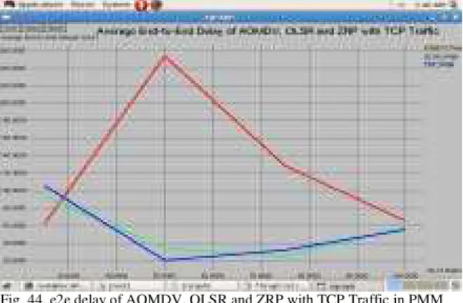
Fig. 44. e2e delay of AOMDV, OLSR and ZRP with TCP Traffic in PMM
From Fig. 35-44, we observed that the End-to-End delay of OLSR is very less in all the five scenarios with respect to both CBR and TCP traffic but it is less in ZRP than in AOMDV of the same scenarios with respect to the same traffics.
VII. CONCLUSIONS AND FUTURE WORK
The Quality of Service (QoS) evaluation of AOMDV, OLSR and ZRP are carried out in terms of five scenario patterns such as RWM, RPGM, MGM, GMM, and PMM in two different traffic patterns such as CBR and TCP using NS2 and Bonn Motion. OLSR is performed well in all the five scenarios and in two traffic patterns. The performance of AOMDV is remarkably good while comparing its performance with ZRP. When we compare the average end to end delay of these protocols, the ZRP is having less delay than AOMDV and OLSR. AOMDV has heavy packet loss than ZRP and OLSR due to route cut-off problem existing in reverse path set up. AOMDV being a well known and widely used on demand routing protocol, its performance will be improved in future by reducing delay in communications.
REFERENCES
[1] Elizabeth M. Royer, C-K Toh, “A Review of Current Routing Protocols for Ad-Hoc Mobile Wireless Networks”, IEEE Personal Communications, April 1999, pp.46-55.
[2] Sapna S.Kaushik, P.R.Deshmukh, “Comparison of effectiveness of AODV, DSDV and DSR Routing Protocols in Mobile Ad hoc Networks”, International Journal of Information Technology and Knowledge Management, Vol. 2(2), pp.499-502, 2009.
[3] R.L.Lagendijik, J.F.C.M.de Jongh, “Multipath Routing in Mobile Ad Hoc Networks”, Traineeship Report, Version 1.2, TU-Delft/TNO, 2003.
[4] M. Marina and S. Das, “On-demand Multipath Distance Vector Routing in Ad Hoc Networks”, in Proceedings of the International Conference for Network Procotols (ICNP), Riverside, Nov. 2001.
[5] S.Corson, J.Macker, “Routing Protocol Performance Issues and Evaluation Considerations”, RFC2501, IETF Networking Group, January 1999.
[6] Mehran Abolhasan, Tadeusz Wysocki, and Eryk Dutkiewicz , “A review of routing protocols for mobile ad hoc networks”, Ad Hoc Networks, June 2003, pp.1-22.
[7] S. R. Das, R. Castaeda, J. Yan, “Simulation-based performance evaluation of routing protocols for mobile ad hoc networks”, Mobile Networks and Applications, 2000,Vol. 5, pp.179–189.
[8] S. Das, C. Perkins and E. Royer, “Ad Hoc On Demand Distance Vector (AODV) Routing”, IETF RFC3561, July 2003.
[9] T. Clausen, P. Jacquet, A. Laouiti, P. Muhlethaler, A. Qayyum and L. Viennot, “Optimized Link State Routing Protocol for Mobile Ad Hoc Networks”, IEEE INMIC, Pakistan 2001.
[10] P. Jacquet, P. Muhlethaler, and A. Qayyum, "Optimized Link State Routing Protocol", IETF Internet Draft, draft-ietf-manet-olsr-10.txt, June 2002.
[11] P. Jacquet and T. Clausen, "Optimized Link State Routing Protocol", IETF Internet Draft, draft-ietf-manet-olsr-11.txt, July 2003.
[12] J. Schaumann, “Analysis of the Zone Routing Protocol”, December 2002.
[13] Z. Haas and M. Pearlman, "The zone routing protocol (ZRP) for Ad Hoc networks", IETF Internet Draft, draft-ietf-manet-zone-zrp-04.txt, July 2002.
[14] Thomas Clausen, Philippe Jacquet, Laurent Viennot, “Comparative study of CBR and TCP Performance of MANET routing protocols”, Technical report, Project HiPERCOM, INRIA Rocquencourt, 2002.
[15] Vikas Singla, Parveen Kakkar,“Traffic Pattern based performance comparison of Reactive and Proactive protocols of Mobile Ad-hoc Networks”, International Journal of Computer Applications, Vol. 5(10), pp.16-20, 2010.
[16] C.P.Agrawal, O.P.Vyas, M.K.Tiwari, “Evaluation of varying mobility models & network loads on DSDV protocol of MANETs”, International Journal of Computer Science and Engineering,Vol. 1(2), pp. 40-46, 2009.
[17] Radhika Ranjan Roy, “Handbook of Mobile Ad Hoc Networks for Mobility Models”, Springer, 2011.
[18] The Network Simulator ns-allinone-2.34, http://www.isi.edu/nsnam/ns/
[19] Kevin Fall, K. Varadhan, "The ns Manual", University of Southern California, Information Sciences Institute (ISI), http://www.isi.edu/nsnam/ns/ns-documentation.html.
[20] NS-2 with Wireless and Mobility Extensions, http://www.monarch .cs.cmu.edu.
[21] The Bonn Motion, http://bonnmotion.cs.uni-bonn.de/
[22] P.Periyasamy and E.Karthikeyan, “Performance Evaluation of AOMDV Protocol based on various Scenario and Traffic Patterns”, International Journal of Computer Science, Engineering and Applications (IJCSEA), Vol.1, No.6, 2011, pp. 33-48.
[23] P.Periyasamy, E.Karthikeyan, “Impact of Variation in Pause Time and Network Load in AODV and AOMDV Protocols”, I.J. Information Technology and Computer Science, Vol.3, pp.38-44, 2012.
Authors Biography
P.Periyasamy is working as an Assistant Professor in the Department of MCA, Sree Saraswathi Thyagaraja College, Pollachi, India. Interested in Mobile Ad hoc Networks Routing Protocols Design and Development.