ISSN 1546-9239
© 2009 Science Publications
Corresponding Author: Mohammad Qatawneh, Department of Computer Science, KASIT, University of Jordan, P.O. Box 13047, Amman 11942, Jordan Tel: 00962-79-5502200 Fax: 00962-6-5681343
Parallel Implementation of Polygon Clipping Using Transputer
Mohammad Qatawneh, Azzam Sleit and Wesam Almobaideen
Department of Computer Science, KASIT, University of Jordan,P.O. Box 13047, Amman 11942, Jordan
Abstract: This research describes a parallel implementation of Liang-Barsky clipping algorithm on a
pipeline network configuration. The implemented configuration uses pipeline of four transputers and programmed under Occam2 language. In order to achieve the concurrency, to improve the performance and to cut down the hold-ups caused by the calculation of intersection, data buffering is used.
Key words: Parallel clipping, transputer, pipeline
INTRODUCTION
Computer graphics is a field of computing which requires intensive processor use. Algorithms in graphics are very repetitive and operate on very large data sets. The process of clipping can be defined as the process of removing the portion of an image that falls outside the visible region. In graphics, there are line and polygon clipping algorithms[3,4,5,7,8]. The polygon clipping algorithm clips a polygon against one boundary window after another, rather than clipping against all boundaries at once. This has certain features which is a natural candidate for parallel implementation.
Several well-known polygon clipping algorithms have been proposed[1,2,4,10,12,13]. The basic idea of these algorithms is to clip a given polygon against each boundary line of the window separately. Both Sutherland-Hogman and Liang-Barsky algorithms generate connected clipped polygons[9,12]. The Liang-Barsky algorithm is optimized for rectangular windows but is extendable to arbitrary convex windows. Results indicate that for rectangular windows the optimized algorithm is twice as fast as the Sutherland-Hogman. Liang-Barsky is a parametric polygon clipping algorithm.
The choice of parallel configuration for a particular problem is not always straightforward. Much research in parallel processing[6,11] is directed towards matching problems to configuration. This research presents a parallel implementation of Liang-Barsky polygon clipping algorithm which is based on a Transputer Development System (TDS). The INOMS T414 transputer[7] is a 32 bit microcomputer with 4Kbytes on-chip RAM for high speed processing, a configurable memory interface, and all necessary system services. It
has four ports of communication links all in single wafer. The programming language Occam[7,11] is a concurrent programming language designed for the transputer. The implemented system uses pipeline of four transputer and programmed under Occam2 language.
DESIGN CONSIDERATION
An arrangement of four processors in a pipeline-configuration is an obvious method of implementing polygon-clipping algorithms[2,3] against four boundaries. Each processor runs the clipping process for a different boundary, where polygon data passes from processor to processor. In addition, four other processes are required to make the pipeline work, these are: Reading and writing data to the pipeline, create the polygon data and to display the resulting clipped polygon.
Figure 1 shows an example of two processes (create and write) accessing the common area of memory have to be synchronized to avoid unpredictable result. The create process can terminate before the write process starts. Also, the boundary data (bound data) and write processes both communicate with clip.bo. Hence synchronization is achieved through the running order of the process. Fig. 2 shows the pseudo Occam which presents the ordering of these processes.
Po ly gon Data
Sh ared memo ry R ead /W rite
B oun d Data W rite C reate
R esu lt R ead
C lip .b0 C lip .b1 C lip .b2 C lip .b3
C lip p ed po lygo n d ate
Fig. 1: The interaction of the main processes
SEQ Create () Bou nd ary d ata
P A R W rite () Clip.b0 () Clip.b2 ()
Cl
Fig. 2: The pseudo code for create and write processes in Occam
Processor n Buffering Clipper
Processor n+1
Buffering Clipper
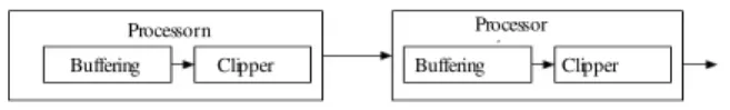
Fig. 3: Clipping to buffering communication
In order to cut down the hold-ups caused by the calculation of intersections by buffering data which are sent by previous processor in the pipeline. The buffering can be done by a process working in parallel with the clipping algorithm as shown in Fig. 3. As the buffering process takes place on the same processor as the clipping processor, concurrency is achieved through multitasking. The buffer improves the performance by allowing a clipping process to pass on its data to another clipping process even if that process is not ready to process the data. This result a reduction in waiting times, however, operating a buffer does introduce an extra processing overhead.
The clipping algorithm wants to know when one polygon ends and the next start otherwise, the list of polygon would be treated as one large polygon. Since the whole polygon list and pointer table are not passed from processor to processor, consequently, they can not be used to find the start, or end of each polygon. The following solutions could be considered:
Fig. 4: Example of data flow between pipe elements
• By passing an integer to a pipeline telling it how many vertices are in the polygon, vertex list is then communicated. However, the clipping process may reduce the number of vertices in the list. This means that the number of vertices in the list cannot be communicated until the entire polygon has been clipped. The result is an undesirable flow of data • A more satisfactory solution is to pass a start of
polygon token. It does not communicate the polygon length. Such token can also be used to signal the end of the polygon list and therefore cause the pipeline element to reset. The token can be a Boolean variable, true for start and false for end of polygon list (an example shown in Fig. 4). Notice, those two true values with no vertices between, signifies that a polygon has no vertices with the window boundaries, and has therefore an empty vertex list. Therefore, only two data types need to be communicated between processes (Boolean and two element integer arrays, holding the (x, y) component of each vertex)
Boundary positions take the form of signal integer values, two giving x-coordinate and two giving y-coordinates. The host sends all four positional values, put in order, to the first processor in the pipeline. The first processor takes the first value and passes the rest onto the second processor and so on.
IMPLEMENTATION OF PIPELINE
The clipping algorithm is implemented on a pipeline of processors using Transputer Development System (TDS). The system consists of host PC (CPU Dual core 2.4 GHz and 1GB RAM), host transputer, and four transputers as shown in Fig. 5. The TDS runs on the host Transputer and provides a folding editor, Occam2 compiler, debugger and various tools. Under TDS, the code which runs on the transputers network is stored in a program fold.
Host PC
Host
Tran-sputer Processor 0 Processor 1 Processor 2 Processor 3
Fig. 5: Transputer development system
Link2 out Host Processor
Link3
Link2 out Processor 0
Link2 out Processor 1
Link2 out Processor 2
Link2 out Processor 3
Link1 in Link1 in Link1 in Link1 in
Protocol vertex.or.Commnd CASE
VER, [2] INT COMM, BOOL
Fig. 6: Links configuration used by the clipping pipeline
The processors are configured to run the procedure called clippoly which can be found in the program fold, which is run on each processor. The input and output channels are different for each processor, as is the boundary against which it clips, which is passed to the processors as parameters. The clip procedure has the parameterization clippoly (input channel, output channel, and boundary). This procedure is effectively called only once when the network is loaded.
The clippoly procedure contains all the code which runs on the pipelining processors. The procedures declared Clippoly are Boundary.Pos Buffer.Space and Liang-Barsky algorithm (LB.algm). The overall structure of the clippoly procedure in pseudo Occam is shown in Fig. 7.
The infinite loop exists so that when the pipeline has finished processing a polygon list, the pipeline processor code resets itself. A reset is the transition to a state where the code running on pipeline processor is waiting for boundary position to be communicated. The followings are the procedures called within Clippoly procedure.
Boundary.Pos: This procedure is invoked for each new
polygon list. The pseudo Occam of this procedure is shown in Fig. 8.
Buffer.Space: To make the operation on the pipeline
more efficient the data is buffered. This process runs concurrently with the clipping algorithm and reads the channel from the previous processor in the pipe. If the clipping code is not ready to receive the data, the Buffer.Space process is suspended until it is. The following Pseudo Occam procedure shows the actions:
SEQ
While more vertices
Get value fro m previous processor, communicate to Clipping code, when ready output vertex.
While True SEQ Boundary.P os () P AR Buffer .Space SEQ
While vertices left to process Input vertex
Clippoly () Output vertex
Fig. 7: Pseudo code of clippoly procedure
SEQ
Loop once for each Processor, which follows in pipe, it read a boundary position from previous processor. If vertex type
If first position read,
Make boundary position = position read Else
P ass on boundary posit ion to next processor. Else
Stop (an error)
Fig. 8 The pseudo occam of Boundary.Pos procedure
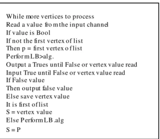
While more vertices to process Read a value fro m the input channel If value is Bool
If not the first vertex of list Then p = first vertex o f list P erfor m LB>alg.
Output a Trues until False or vertex value read Input True until False or vertex value read If False value
Then output false value Else save vertex value It is first of list S = vertex value Else P erform LB .alg S = P
Fig. 9: The pseudo Occam of Clippoly procedure
A more conventional circular buffer could be used. This has the advantage that the storage size of the buffer does not effect the processing time needed to operate the buffer.
Clippoly code: This is the main part of the procedure,
SEQ Initialize () Boundary Data () Start timing P AR Write data () Read data Stop timing Results
Fig. 10: Interface pseudo code
The interface program runs on the host Transputer. Its code is completely separated from the clipping code. All interactions between the interface and the clipping code take via channel communication. The interface code is illustrated in Fig. 10.
RESULTS AND DISCUSSION
The main draw back in using a pipeline for polygon clipping is that of processors being forced to wait for one another to finish tasks. This problem is addressed by the use of a buffer. However, due to the overhead of operating a buffer, only a single element buffer is used. Experiments with a circular buffer show that between 10-20 data items are being queued up. The buffer used is therefore only going a small way to deal with the hold up problem.
The same causes of hold-up exist on a single processor system. However, on a single processor, a process which has to wait for another process does not cause the processor to be kept idle. Instead a runnable process is run (i.e., Processes are multi-tasked). Therefore, the processor in the single processor implementation will always be kept busy; keeping the processor busy maximizes performance. The amount of clipping which has to be done has a direct effect on the number of hold-ups caused. For example a processor in the pipeline may have to perform no clipping because the polygons are all visible, but neighbor processor in the pipeline, on the other hand, might be clipping for a boundary, which passes through the polygons. The result is that one processor takes longer to process the same data as the other one, such a load imbalance will cause hold ups. It is found that the speed up is more or less perfect for four or five processor implementation. However, two processors implementation is unique in that it employs the best attributes of the single processor and multi processor implementation, which are respectively multitasking and parallel processing. Multitasking allows each of the processors to alternate between the two clip processes. Parallel processing allows boundaries 0 and 1 to be clipped at the same time as boundaries 2 and 3.
The processor pipeline performance is at its worst when there is a lot of clipping and vertex exclusion. It might be expected that a heavy workload would favor the parallel system, since it would keep the processors busy.
CONCLUSION
A parallel implementation of a polygon clipping algorithm on a pipeline of four transputers is presented and implemented, in order to provide a high speed-up over sequential implementation of the graphics operations concerned. Transputer Development System (TDS) hardware is implemented. The procedure code which runs on the pipeling processors also is written in Occam.
The advantage of using general purpose parallel processors rather than special purpose architecture include low development costs (only the software has to be developed) and a large degree of flexibility. Users of general purpose parallel processors can reduce their investment in graphics hardware by using algorithm presented here in order to achieve high graphics performance.
REFERENCES
1. Ari Rappoport, 1991. An efficient algorithm for line and polygon clipping, the visual computer. Int. J. Comput. Graph., 7 (1): 19-28.
2. Bui, D.H. and V. Skala, 1999. New fast line clipping algorithm in E2 with O (lgN) complexity. International Conferences SCCG’99, Budmerice, Slovak Republic, pp: 221-228.
3. Daniel, C. Hyde, 1995. Introduction to the Programming Language Occam.
4. Day, J.D., 1992. A new two dimensional line clipping algorithm for small windows. Comput. Graph. Forum, 11 (4): 241-245.
5. Francis Hill, 2000. Computer Graphics Using OpenGL, Amazon.
6. Gray, J.P., Technology and Practice (PCAT-94), Transputer and Occam Engineering Systems, Parallel Computing, pp: 43-53.
7. James S. Pascoe, 1993. World Occam and Transputer User Group Technical Meeting- Technology, 2002. Kai Huwang, Advanced computer Architecture: Parallelism, scalability, Programmability, McGraw-Hill.
9. Liang, Y.D. and B.A. Barsky, 1984. A new concept and method for line clipping. ACM Trans. Graph., 3 (1): 1-22.
10. Lu, G.D., X.H. Wu and Q.S. Peng, 2002. An efficient line clipping algorithm based on adaptive line rejection, Comput. Graph., 3 (26): 409-415. 11. Nicole, D.A., 1988. Occam and Transputer Tutorial
at a Conference on Economical Parallel Processing, Berne, Switzerland.
12. Sutherland I.E. and Hodgman G.W., 1974. Reentrant polygon clipping. CACM, 17 (10): 32-43.