New developments in high quality grey cast
irons
*Iulian Riposan, Mihai Chisamera, and Stelian Stan POLITEHNICA University of Bucharest, Romania
Abstract:
The paper reviews original data obtained by the present authors, revealed in recent separate publications, describing speciic procedures for high quality grey irons, and relecting the forecast needs of the worldwide iron foundry industry. High power, medium frequency coreless induction furnaces are commonly used in electric melting grey iron foundries. This has resulted in low sulphur (<0.05wt.%) and aluminium (<0.005wt.%) contents in the iron, with a potential for higher superheating (>1,500 °C), contributing to unfavourable conditions for graphite nucleation. Thin wall castings are increasingly produced by these electric melt shops with a risk of greater eutectic undercooling during solidiication. The paper focused on two groups of grey cast irons and their speciic problems: carbides and graphite morphology control in lower carbon equivalent high strength irons (CE=3.4%-3.8%), and austenite dendrite promotion in eutectic and slightly hypereutectic irons (CE=4.1%-4.5%), in order to increase their strength characteristics. There are 3 stages and 3 steps involving graphite formation, iron chemistry and iron processing that appear to be important. The concept in the present paper sustains a three-stage model for nucleating flake graphite [(Mn,X)S type nuclei]. There are three important groups of elements (deoxidizer, Mn/S, and inoculant) and three technological stages in electric melting of iron (superheat, pre-conditioning of base iron, inal inoculation). Attention is drawn to a control factor (%Mn) x (%S) ensuring it equals to 0.03 – 0.06, accompanied by 0.005wt.%–0.010wt.% Al and/or Zr content in inoculated irons. It was found that iron powder addition promotes austenite dendrite formation in eutectic and slightly eutectic, acting as reinforcement for the eutectic cells. But, there is an accompanying possible negative influence on the characteristics of the (Mn,X)S type graphite nuclei (change the morphology of nuclei from polygonal compact to irregular polygonal, and therefore promote chill tendency in treated irons). A double addition (iron powder + inoculant) appears to be an effective treatment to benefit both austenite and graphite nucleation, with positive effects on the final structure and chill tendency.Key words:
grey iron; S; Al; Zr; Ti; electric melting; furnace superheating; preconditioning; inoculation; graphite nucleation; graphite morphology; carbides; dendritic austenite; iron powderCLC numbers: TG143.2 Document code: A
Article ID: 1672-6421(2014)04-351-14
*Iulian Riposan
Born in 1948, Ph.D, Professor. Major research areas: lamellar, nodular, compacted/vermicular and coral graphite irons-processing and complex characterization; austempered castingirons with LG, NG, CG or coral graphite; cast iron matrix composited; new modifying techniques for cast irons; cupola and electric furnaces operations. Publications: over 250 published papers; three books (CG Iron – 1984, White Irons – 1985 and Bainitic Irons - 1989) and one textbook (Cast Irons - 1985); 35 Romanian patents. He is now the President of Romanian Foundry Technical Association (ATTR).
Fig. 1: Foundry metallic materials evolution worldwide (a, b,c) and 2012 structure (d) [1]
Fig. 2: Inluence of CE on mechanical (a) and physical characteristics (b) of grey cast irons [Rm - Tensile Strength (MPa); E - Elastic Modulus (GPa); HB - Brinell Hardness; λ- Thermal Conductivity (W·m-1
·k-1
); d - Density (g·cm-3 ×
10); ρ-Electrical Resistivity (Ω·mm2·m-1
× 102); δ
- Vibration Damping Capacity (10-4 )]
I
n 2012, a year after world casting volume exceededpre-2008 levels, global castings production increased to more than 100 million metric tons (Fig. 1) [1]. Grey cast iron is still the most used foundry metallic material, at 46% of this total world castings production. Grey iron is used to advantage in the automotive industry, because of its excellent properties such as machinability, heat conductivity and vibration damping capacity. These properties in combination with reasonable strength are why grey iron has maintained its position as the primary choice for the production of vital engine components for vehicles. In this respect, emphasis on thin wall castings can be seen as the current trend in automotive engineering applications.
In order to satisfy the designer’s demands for component
strength, most engineering grey irons are hypoeutectic compositions. The highest strength is obtained with the lower carbon equivalent levels (CE=3.4%- 3.8%), maintaining reasonable thermal conductivity, vibration damping capacity and machinability (Fig. 2a) [2,3]. The most important challenge for these iron castings, especially for high cooling rates associated with thin wall castings, is the increased tendency to carbide formation, in metastable solidiication conditions. The promotion of type-A graphite morphology also requires more process management.
Near eutectic to slightly hypereutectic composition irons (CE = 4.1%-4.5%) show the best combination of castability, tensile strength and thermal properties for thin wall castings (Fig. 2b) [2,3]. A critical problem for these irons is the limited
120 110 80 60 40 20 0
Million
tons
Years
19981999200020012002 2003 2004 2005 2006 2007 2008 2009 2010 201 1
2012
(a) 50
40
30
20
10
0
Million
tons
Gray iron
Ductile iron
Aluminum
Steel
2004 2005 2006 2007 2008 2009 2010 2011 2012 Years
(b)
Grey lron Ductile lron Steel Non ferrous
70 60 50 40 30 20 10 0
Production
rate
(%)
Production rate Years/
Years
1998 19992000 20012002 2003 2004 2005 2006 2007 2008 2009 2010 201 1
2012 (c)
17% nonferrous: 17.1 million tons
46% gray iron: 46 million tons 11% steel:
11.3 million tons
25% ductile iron: 25.2 million tons (d)
Hypo eutectic irons- Hyper eutectic irons
-500
400
300
200
100
0
3 3. 3 4. 3 5. 3 6. 3.7 3.8 3.9 4.0 4.1 4.2 4.3 4.4 CE (%) HB
E R
m
*
*
*
*
*
*
3 3. 3 4. 3 5. 3 6. 3.7 3.8 3.9 4.0 4.1 4.2 4.3 4.4 CE (%)
Hypo eutectic irons
-160
140
120
100
80
60
40
20
0
Hyper eutectic irons
-λ
δ
ρ
d
tensile strength, due to the low amount of austenite dendrite formation during primary solidiication and the formation of a pearlitic matrix during eutectoid transformation, respectively.
The investigation found that the optimum tensile strength could be obtained in as-cast grey iron by avoiding carbides, increasing the amount of primary austenite dendrites, reining the eutectic cell size, maximizing the percentage of medium sized type A graphite and establishing an entirely ine pearlitic matrix structure, at pearlite spacing less than 0.8 mm.
Important changes in worldwide grey iron castings production have been observed:
(1) Historically: cupola melted irons are characterized by a chemistry, including > 0.5wt.% Mn, > 0.05wt.% S, > 0.005wt.% Al, (%Mn) × (%S) > 0.03, providing favourable conditions for MnS-type compounds, which are found to be major nucleation sites for lake graphite and correspondingly low chill tendency in grey cast irons.
(2) Small and/or ineficient cupolas have been replaced by a new generation of acid lined coreless induction furnaces [200 -1000 Hz frequency, > 250 kW/ton specific power]. These furnaces became successful replacements for the smaller cupolas because they have a high melting rate, do not require a molten heel, can melt high steel charges with reasonable stirring capacity, and with the ability to reach superheating temperatures > 1,500 o
C. The tapped iron chemistry is characterized by > 0.5wt.% Mn, < 0.05wt.% S, < 0.005wt.% Al, (%Mn) × (%S) < 0.03, which does not support suitable MnS-type compound formation. As a result, high chill and/or undercooled graphite formation tendencies increase.
(3) Producing grey, ductile and compacted graphite irons in the same foundry with the same furnace or from the same heat increasingly represents actual industry practice, with important and inarguable advantages [a single low sulphur base iron, using a single inoculant, > 1,500 oC furnace bath temperature]. The compromise chemistry of this single base iron, with < 0.5wt.% Mn, < 0.03wt.% S, < 0.005wt.% Al, (%Mn) × (%S) < 0.02, is desirable for ductile and compacted graphite irons, but creates some issues for grey iron due to the higher risk of chill and undercooled graphite.
(4) There has been a noticeable transition from medium thick wall castings at > 10 mm section size to thinner wall castings < 10 mm, particularly <5 mm, especially in the automotive industry. The percentage of world casting production by grey iron reduced in the last 15 years, from 52%-54% to 45%-46% in favour of ductile iron and aluminium alloy castings (Fig. 1b and 1c), especially due to replacement of medium thick wall castings with thin wall castings. The higher solidiication rate with these castings leads to more eutectic undercooling, with risk of carbides formation or at least type D, E, B undercooled lake graphite morphologies.
(5) A significant segment of the world cast iron foundry industry employs electric melting without or with limited pig iron in the mainly steel and iron scrap charge, operating at low sulphur and aluminium contents, but with other higher
residuals (Cr, Mo, Pb, Sn, N etc.), at high superheat (>1,500 o
C) for thin wall castings. The combination of such unsuitable conditions for solidification with low eutectic undercooling leads to an exaggerated risk of carbides and undercooled graphite morphologies forming, especially if the carbon equivalent is well below the eutectic value.
The objective of this paper is to review original data obtained by the present authors, to respond to the observed important worldwide changes in grey iron melting technology, with effective metallurgical treatments to compensate for these conditions. The findings affect carbides, eutectic cells and graphite morphology control in hypoeutectic irons and austenite dendrite promotion in eutectic and slightly hypereutectic irons.
1 Hypoeutectic grey cast irons
Hypoeutectic grey cast irons have traditionally been produced because of their greater mechanical properties due to the higher austenite dendrite/eutectic cells ratio. They can be produced without carbides, while having a refined Type A graphite morphology, with a iner eutectic cell size (increased cell count).
In commercial grey irons, solidified in non-equilibrium conditions, typical for foundry mould media, an as-cast structure is generally heterogeneous, including different amounts of carbides, different graphite morphologies and variable pearlite/ferrite ratios [Fig. 3(a)].
Final casting structure could be totally changed to the most favourable parameters such as a homogeneous structure, including Type-A graphite, a pearlite matrix with very limited or no carbides [Fig. 3(b)], by applying effective molten iron inoculation.
Inoculation is the most important metallurgical treatment applied to the molten iron immediately prior to casting, with direct effects on the primary structure (austenite, carbides, eutectic cells, graphite characteristics). Indirectly, it inluences the eutectoid structure, especially pearlite/ferrite ratio, which is dependent on the graphite amount and especially its morphology. The most important aspects of a grey iron inoculation treatment are as follows:
(1) Addition of 0.05wt.% to 1.0wt.% inoculant in the inal iron melt as it is transferred [1,300-1,500 oC];
(2) Inoculants: FeSiAlX alloys, where X = Ca, Ba, Sr, etc. are inoculating elements, to promote and participate in the creation of micron sized active compounds in the iron melt, to act as effective graphite nucleation sites. The well inoculated iron undergoes less eutectic undercooling, as a result of the improvement of existing nucleation sites or by new nucleation sites development;
(3) Factors inluencing inoculation eficiency:
- Charge materials [pig iron/steel scrap ratio, recarburizers, preconditioners]
- Base iron chemical composition [Si, Mn, S]/iron residuals [Al, Ti, O, N]
- Inoculating elements/inoculant type/inoculation procedure - Holding time / pouring procedure
- Casting characteristics
(4) Inoculation plays a vital role in the continuing development of cast iron by controlling the graphite nucleation mechanism.
In commercial grey irons, solidified in foundry mould media conditions, heterogeneous graphite nucleation must be considered, as only when liquid iron undercools sufficiently (200-230 oC), can the smaller sizes of micro cluster (C
6)n exist as stable homogeneous nuclei for graphite particles [4].
Under normal conditions, such high undercooling is dificult to achieve. Therefore, the nucleation of graphite is mainly driven by heterogeneous nucleation, such as residual graphite particles and/or non-metallic micro-inclusions. High residual graphite dissolution in the base iron could be expected, especially for low S (<0.05wt.% S), high superheat (>1,500 oC) type irons, typical of the latest medium frequency electric induction melting furnaces.
Practically, only pre-existing and newly formed micro-inclusions act as substrates for nuclei or graphite nuclei in commercial grey irons, depending on melting practice, iron chemistry, molten iron treatments, solidification conditions, thermodynamic conditions for formation of compounds, which have similar (suitable) or contrasting lattice parameters (unsuitable) to those of graphite.
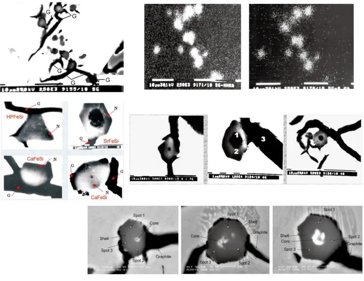
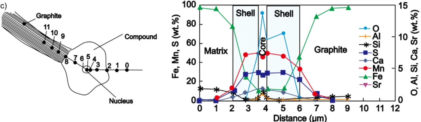
Considering the particles that might become nuclei, thermodynamics indicates that oxides (silicates) and sulphide (S) compounds are more probable to form in the iron melt, due to their free energy of formations being more negative than those for nitrides or carbides. MeO-SiO2 compounds are characterized by a hexagonal crystallographic system, with a favourable wetting relationship, and a satisfactory lattice disregistry, so with that compatibility they appear to be candidates for graphite nuclei. MeS-type compounds, mainly in the cubic crystallographic system, very much different than graphite, would appear to have problems in nucleating graphite. However, a transition from MeS to complex (Me,X)S compounds, where X represents mainly active elements, is a possible route to increase their capacity to nucleate graphite. In commercial grey irons, (Mn,X)S compounds were found to be significant sites for graphite nucleation by the present authors (Fig. 4) [5-17]. The presence of X could be from a contribution by the charge materials, a preconditioning addition or an inoculating treatment. A typical example is presented in Fig. 5 [6]. Different degrees of contact between the inclusions and graphite were found: no visible contact with graphite as a particle embedded in the matrix; supericial contact between inclusion and graphite; or partial and total encapsulation by graphite.
Recent studies have identiied possible stages for nucleation and subsequent graphite precipitation in grey irons. By employing advanced electron microscopy in the investigations, it has been revealed that a nucleus for a graphite lake consists Fig. 3: As cast grey iron structure (a) and inal structure after inoculation (b)
(a) Heterogeneous as-cast structure (Carbides / Pearlite / Ferrite / D, E, B, A, C - type graphite)
Fig. 4: Typical graphite nucleation sites in commercial grey cast irons
0 1 2 3 4 5 6
7 Compound
Graphite
*
10080
60 40
20
0
0 1 2 3 4 5 6 7 8
Fe Mn S
*
SiDistance ( m)μ
*
*
*
*
Shell Graphite
Matrix 20
15
10
5
0
Si
(w
t.%)
Fe
Mn
S
(wt
,
,
.%)
*
*
* *
0 1 2
3456
7 89
10 1112
Graphite
Compound
Nucleus
*
100
80
60
40
20
0
Fe
Mn
S
(wt
,
,
.%)
* *
* * *
*
*
* *
15
10
5
0 O
AI
Si
Ca
Sr
(wt
,
,
,
,
.%)
Mn S
*
SiFe O AI
Ca
Sr Matrix
Shell
Core
Shell
Graphite
Matrix
*
0 1 2 3 4 5 6 7 8 9 10 11 12
Distance ( m)μ
(a)
of a particle with an initial nucleus core of complex oxide surrounded by a sulphide body. The hypothesis: oxides are irst to form as stable micro-inclusions in the iron melt and act as effective nucleation sites for complex (Mn,X)S sulphides. A three-stage model for the nucleation of graphite in grey iron is proposed and illustrated in Fig. 6. According to this proposed three stage model for the nucleation of graphite in grey iron, it is found that three groups of elements are important in the grey iron chemistry, to support graphite nucleation at lower levels of eutectic undercooling.
(1) Strong deoxidizing elements, such as Al and / or Zr,
promote the formation of very small oxide-type micro-inclusions, which are able to nucleate MnS-type particles with favourable characteristics to support nucleation of a type A graphite morphology.
(2) Mn and S in a balance to sustain MnS type sulphide formation, the most important nucleation sites in commercial grey cast irons.
(3) Inoculating elements (such as Ca, Sr, Ba, Ce, La) participate in the irst stage or in the second stage of graphite formation, improving the ability of (Mn,X)S compounds to nucleate graphite.
Fig. 6: Typical example of a three stage model for nucleation of graphite in grey iron
Due to their relatively high concentration in the iron melt, Mn and Si might be expected to be the principal candidates to contribute to the formation of oxides. It was found that this is only true at very low levels of Al in the iron melt (<0.002wt.% Al). In contrast, at more than 0.004wt.% residual Al in the iron, the Al content in these cores of (Mn,X)S compounds is more than 10 times higher than that of Si. This is in accordance with the preferential deoxidizing role of Al to form oxides ahead of Si.
In specific conditions, the first formed micro-inclusions were found to also contain Zr or Ti. Zirconium was not found in the (Mn,X)S compounds unless there was a Zr addition in the iron melt, despite the possible carryover presence of residual Zr in these irons. At low contents of Zr and Al in the melt, the core within the nuclei had a high concentration of Al, while Zr was not detected. When Zr was added to the
iron, all of the micro-inclusions, which acted as graphite nuclei, showed considerable Zr concentration in the core and shell of (Mn,X)S compounds. Ti presented in the irons with an intentional pre-addition of Ti, but without a Ti addition the typical Ti residual was 0.003wt.%-0.008wt.% in the molten iron.
Figure 7 illustrates the main characteristics of complex ( M n , X ) S c o m p o u n d s , w h i c h w e r e i n f l u e n c e d b y preconditioning additions of different deoxidizing elements (Ti, Al, Zr) prior to inoculation. These compounds were found to act as graphite nucleation sites in Sr-FeSi inoculated grey irons, with Fig. 7 showing the resultant graphite morphologies in the final irons [5,14-18]. Both Al and Zr additions increased the number of micro-inclusions with Zr generating twice the number of particles compared to Al, with a smaller average size. A Ti addition did not increase the count but increased
Graphite 11
10 9
8 7 6 5 43 1 0 2
Compound
Nucleus
Mn S
*
SiFe O AI
Ca
Sr Shell
* * *
* ** *
*
* * *
Shell
Matrix Core Graphite
100
80
60
40
20
0
F
e
Mn
S
(wt
,
,
.%)
0 1 2 3 4 5 6 7 8 9 10 11 12
15
10
5
0 O
AI
Si
Ca
S
,
,
,
,
r
wt(
.%)
Distance ( m)μ
Fig. 5: Chemical composition changes along a line through core of sectioned (Mn,X)S compounds (wt.%): un-inoculated iron (a); Sr-FeSi un-inoculated iron (b); Ca-FeSi un-inoculated iron (c)
1 Nucleus AlO·XO 2
Body (Mn,X)S
3 Graphite
1 - Oxide based sites
(< 3 μm), formed early in the melt as stable micro-inclustions of deoxidizing elements, Mn, Si, Al, Ti, Zr...
3 - graphite nucleates on the sides of the (Mn,X)S with suitable crystallographic it with graphite (X - element from inoculant)
2 - complex (Mn,X)
S compounds (1...10 μm) nucleate at oxide-based sites (X = Fe, Si, Al, Zr, Ti, Ca, Sr, P, Ce, La...)
the average size compared to the reference sample. Of note is the dependence of the morphology of these graphite nucleation sites on the type of preconditioner. Generally, the compounds have a polygonal shape, mainly irregular in the reference iron (un-preconditioned), quasi-regular or regular shape in Al and Zr preconditioned irons, while particles with an indented outline, like a dendrite, were found in irons preconditioned with Ti. The final graphite morphologies in these irons are directly determined by these characteristics of the nucleation sites: type D undercooled graphite is present in un-preconditioned iron and especially after Ti-preconditioning, while irons pre-treated with Al or Zr show a predominantly type A graphite structure. This speciic effect of Ti was also found in other experiments and can explain the sensitivity of grey irons to form undercooled graphite morphology in the presence of titanium.
The graphite particles evolved from the nucleation site, covering partly or enveloping the nucleation site entirely. It
seems that smaller, more compact particles favour a simpler evolution of graphite with less tendency for branching, as with type A graphite (Fig. 7). This was observed to a degree with Al preconditioned irons but more with Zr preconditioned irons. Large particles have a complex morphology, and are associated with a higher branching tendency of graphite, as with type D graphite (uninoculated and Ti treated irons) in irons with greater undercooling. The experiments showed that despite the presence of 0.004wt.%-0.006wt.% Al in the iron immediately after melting, and any subsequent addition of Al, the Al content in the inal iron after holding would be too low to support graphite nucleation. As a result, Al or Zr added in a preconditioning treatment, usually during transfer of the base iron but before inoculation, is a better technique to improve graphite nucleation with less eutectic undercooling. It was found that 0.004wt.%-0.010wt.% Al residual in the iron appears to be beneicial in this respect, without causing pinholes [5, 6, 26].
Fig. 7: Graphite nuclei [(Mn,X)S compounds] characteristics and resulted graphite particles morphologies in
un-preconditioned (R) and Ti, Al or Zr preconditioned and Sr-FeSi inoculated grey irons 1000
800
600
400
200
0
10
8
6
4
2
0
Graphite
nucleants
count
(mm
)
-2 Count
Size
R Ti Al Zr
Graphite nucleants average size (
μ
m)
T h e i n f l u e n c e o f t h e e l e m e n t S , i n d i v i d u a l l y o r i n conjunction with Mn content, has a long history in cast iron. Generally, it is accepted that in grey irons, a controlled relationship between Mn and S contents is necessary, and it is expressed in different ways:
%Mn = 1.7 (%S) + 0.2 – 0.4 (1)
(%Mn) / (%S) = 5 – 15 (2)
(%Mn) × (%S) = 0.03 – 0.06 (3)
Equation 3 was proposed by R. Gundlach [21] as a result of reviewing the most important historical data on the inluence of Mn and S on grey cast irons, and complies with the “three-stage model” of lake graphite nucleation in commercial irons, based on the key role of (Mn, X)S compounds [6]
.
compared to an iron with this control factor less than 0.02 [13,14]. The beneicial effects of ensuring the factor (%Mn) × (%S) is in the range 0.05-0.06, rather than the 0.015-0.020 lower range, is illustrated in Fig. 9, for both un-inoculated and Ba or Ca or Sr inoculated irons [22]. Three different FeSi based alloys (75wt.%-76wt.% Si) were used as inoculants: Ba-FeSi (1.0wt.% Ba), Ca-FeSi (1.2wt.% Ca) and Sr-FeSi (1.2wt.% Sr). The inoculants had particle sizes in the range 0.2-0.7 mm and were added at levels of 0.4wt.% during transfer of the iron into the pouring ladle. These hypoeutectic CE=3.7%-4.0% irons were poured at 1,340-1,350 oC into furan resin sand mould, as W3 type wedge samples, specified in the ASTM A 367. Inoculation was effective for all the inoculating elements tested, with favorable effects of higher sulphur on both un-inoculated and inoculated irons, mainly for Ca and Sr treated irons.
A separate experimental programme [14, 23] compared typical base irons of ductile iron with very low sulphur content and grey iron at higher sulphur content, where both might be used for grey
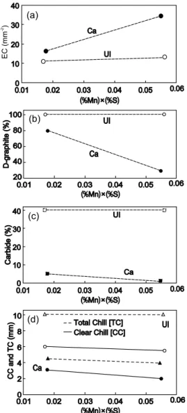
Fig. 8: Inluence of (%Mn) × (%S) factor on clear chill (CC) and total chill (TC), carbides and undercooled graphite (type-D) and eutectic cell count (EC) of un-inoculated and Ca-FeSi inoculated irons
Fig. 9: Inluence of (%Mn) × (%S) factor and inoculating element (Ca, Ba, Sr) on total chill formation in grey cast iron
furnaces, and superheated to 1,500-1,550 oC. The iron had a low sulphur content typical of electric melting (0.020wt.%-0.025wt.% S) and was also re-sulphurized with a FeS furnace addition, after melting and deslagging, to 0.07wt.%-0.09wt.% S, for a range of Mn content, usually 0.45 wt.%-0.75wt.% Mn. The graphs in Fig. 8 refer to 3.8%- 3.9%CE irons, un-inoculated and also 0.4wt.%Ca-FeSi ladle un-inoculated irons. Standard W2 wedge test specimen (ASTM A 367) was used for evaluation of clear chill (CC) and total chill (TC). Round test bars were used for structure analysis: 10 mm diameter bars helped to assess carbides and undercooled graphite type-D, and 30 mm diameter bars were used for eutectic cell count. Iron was poured into furan resin sand moulds in a 1,340-1,350 o
C temperature range. Ca-inoculation appears to have the most beneit on all the measured structure parameters, but increasing the (%Mn) × (%S) factor also acts favourably, especially in inoculated irons to prevent undercooled graphite and increase eutectic cell count. Generally, inoculation of an iron if the (%Mn) × (%S) factor was more than 0.05 was more eficient,
40
30
20
10
0
Ca
UI
0 01. 0 02. 0 03. 0 04. 0 05. 0 06. (%Mn ×) (% )S
EC
(mm
)
-2
100
80
60
40
20
Ca UI
0 01. 0 02. 0 03. 0 04. 0 05. 0 06. (%Mn ×) (% )S
D-graphite
(%)
40 30 20 10 0
Ca UI
0 01. 0 02. 0 03. 0 04. 0 05. 0 06. (%Mn ×) (% )S
Carbide
(%)
10
8
6
4
2
0 Ca
UI
0 01. 0 02. 0 03. 0 04. 0 05. 0 06. (%Mn ×) (% )S
Total Chill [TC] Clear Chill[CC]
CC
and
TC
(mm)
UI
Ba
Sr
Ca
0 0. 1 0 0. 2 0 0. 3 0 0. 4 0 0. 5 0 0. 6 (%Mn) (% )× S
0 07. 20
15
10
5
0
T
otal
chill
width
(mm)
iron castings production, by measuring eutectic undercooling and carbidic tendency. At extremely low sulphur content, less than 0.01wt.%, typical for ductile base iron, the iron solidiied without graphite in the structure. Ca-FeSi inoculation changed the iron structure from white to mottled, with carbides forming at the beginning of the eutectic reaction, followed by graphite formation at the end of the eutectic reaction. Conventional inoculation had less effect at this excessively low sulphur content. In contrast, a higher sulphur content, 0.07wt.%-0.09wt.% S, in the base iron, representing resulphurized electric melt iron, supported graphite formation during solidification. The base iron changed from a white iron (carbides) to a mottled iron (carbides + graphite), while inoculated iron changed from a mottled to a grey (graphitic) microstructure.
There appears to be two solutions for low S grey cast irons: (1) re-sulphurize the base iron to reach > 0.03 for the (%Mn) x (%S) control factor, but the S source presents a quality control issue and an unpleasant working environment; (2) use special inoculants that still perform in low S grey cast irons; these involve the rare earth [RE] group of elements [Ce, La, Pd, Y], more unusual combinations of inoculating elements (Zr + Sr, Zr + Ca, RE + Ca) or upgraded [optimized] conventional inoculants. When the inoculating elements Ca, Sr, Ce, La were detected,
(a)
(b)
(c)
they were found to have an irregular distribution pattern in different sections of the (Mn,X)S compounds.
(1) Ca is present in most (Mn,X)S compounds, including irons inoculated with FeSi based alloys incorporating other inoculating elements. The maximum Ca level was observed in Ca-FeSi treated irons. Ca appears to be similarly distributed in the shell and core, with a Ca[shell]/Ca[core] ratio of 0.5 : 1.0.
(2) Sr was found mainly in the core of the nuclei of graphite but only if the irons had been inoculated with a Sr-FeSi alloy. The Sr distribution pattern showed two distinct ields. Approximately 75% of the compounds analyzed had up to 2.0wt.% Sr in the core and up to 1.5wt.% Sr in the shell, while others had substantially more with up to 20wt.% Sr in the core and < 1.5wt.% Sr in the shell.
(3) When Al or Zr was added, Sr and Ca levels increased in the shell of (Mn,X)S compounds. This was also associated with improved graphite nucleation performance with less eutectic undercooling.
(4) The typical inclusions observed in the iron after inoculation with a La, Al, Ca-FeSi alloy were similar in build up as previously documented complex (Mn,X)S particles with the difference that the core of the (Mn,X)S particles had a La-rich phase surrounding an Al-La-rich phase [5-7, 11-13]. Therefore, La appears to form inclusions later than Al, since the La-rich phase surrounds an Al-rich phase and conirms the key-role of Al in the first stage. These complex Al-La inclusions are possibly better nucleation sites for (Mn,X)S, while the presence of both La and Ca in the shell of the (Mn,X)S makes these inclusions better nucleation sites for graphite (Fig. 10) [9]. The role of La with Ca and Al seems to be dual purpose: assisting with the formation of the early particles and then further modifying the newly created particles to become effective nucleation sites for the ultimate target – graphite.
more readily by coalescence. After the charge materials are melted, the liquid metal can be considered to be in a colloidal state, which consists of a Fe-C-Si (Xi) base solution with suspended remnant graphite particles (0.1 to 10.0 μm) and non-metallic inclusions [14,16,24]
. The condition of the liquid iron is heavily dependent on the quality of the original charge materials but after superheating the bath, the condition changes. The liquid iron evolves from a colloidal liquid state after melting (suspension of graphite particles) through quasi-homogenous up to a quasi-ideal solution. Superheating the bath is useful to dissolve leftover coarse graphite, to float coarse inclusions to the slag layer and to de-activate some of the micro-inclusions, which could potentially be nuclei for graphite. Excessive superheating however will ultimately destroy the intrinsic nucleation capability of the molten iron, resulting in a solidiication structure with undercooled graphite morphologies and iron carbides.
(2) The second step is to pre-condition the iron with oxide forming elements, such as Al and/or Zr, which will be at lower levels after induction melting. These elements create the cores or substrates for the subsequent nuclei. Al and/or Zr form oxide-based micro-inclusions, able to encourage nucleation of (Mn,X) S compounds, with favourable characteristics (high number, small size, compact morphology) for ultimate nucleation of the graphite shapes with less eutectic undercooling during solidification of the iron. An Al content of 0.005–0.010wt.% is recommended to minimize pinholing, especially in green sand moulds, while ensuring sufficient Al content to obtain a desirable graphitization result. At this Al level, the surface tension of molten iron is high enough so that hydrogen pick-up from moisture in a green sand mould is limited. Pre-conditioning is recommended to raise the base line nucleation level, especially for low quality charge materials or non-optimal melting practices, or to compensate for low performance inoculation, either due to procedure or pouring practice.
(3) The third, and final, critical step is inoculation with Ca, Sr, Ca+Ba, Ce or La-FeSi inoculant, to control eutectic undercooling and recalescence during solidiication, in response to the base iron quality and casting characteristics. For a preferred range of Mn and S, using the control factor (%Mn) × (%S) = 0.03–0.06 with a inal content of 0.005wt.%–0.01wt.%Al or Zr, commercial inoculants are beneficial for a controlled graphitization result. Inoculants with a typical 1% inoculating elements content, such as the elements in this group, 0.5wt.% –2.5wt.% Ca, Ba, Sr, Ce or La, are added at a rate of 0.2wt.%– 0.8wt.%, depending on the inoculation technique as well as the casting characteristics. If sulphur levels are not adjusted to within the preferred range, the inoculant selection changes, and inoculant chemistry choice becomes very limited [25]
.
Figure 11 illustrates the results obtained when the base iron, heated to and tapped at 1,530 oC, was poured directly in the resin sand mould at 1,350 oC, alternatively some samples had been subjected to different treatments prior to tapping [11,14,19]. The samples had been either pre-conditioned in the melting furnace Fig. 10: Speciic distribution of Al, Ca and La in core and
shell of (Mn,X)S compounds - average values
AI Ca La
0 5 10 15 20 25
4.0
3 5
3.0
2 5
2.0
1 5
1.0
0 5 0
.
.
.
.
AI Ca La, , (core) (wt.%)
AI
Ca
La
shell
wt
%
,
,
(
)
(
.
)
Three technological steps appear to be necessary to produce high performance grey cast iron via electric melting.
2 Dendritic austenite
evolves from eutectic to
slightly hypereutectic
grey irons
A c c o r d i n g t o t h e F e - C e q u i l i b r i u m p h a s e diagram, dendritic austenite is typically present in hypoeutectic iron. But, data in this diagram was measured in a special environment at a very slow cooling rate: 0.5 – 2.5 oC·min-1 [0.008 – 0.04 oC·s-1], using pure materials melted under vacuum [4].
In foundry practices, commercial irons contain more than 30 elements, in a general system Fe-C-Si-X, and the solidification rates in typical mould media are many times higher. A typical example is solidiication of wedge samples, according to the ASTM A 367 speciication, presented in Fig. 12 [29]
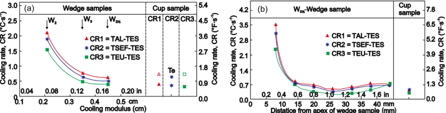
. The calculated cooling rates differentiate the solidiication patterns of the standard wedges: 1.5-2.0 oC·s-1 for W2, 0.5-0.8 oC·s-1 for W3 and 0.4-0.5
o
C·s-1 for W3½ wedge, respectively. For W3½ wedge solidification, the highest cooling rate was recorded close to the apex of the wedge, as is expected for any of the wedges (more than 2 oC·s-1), which led to a white iron type solidiication. The slowest cooling rate, at less than 0.5 oC·s-1, is typical for the thermal center of the W3½ wedge sample [around 25 mm from the apex = 0.5-0.6 H level]. Towards the base of the wedge, cooling rate increased again (0.5- 0.7 oC·s-1), despite the greater section width, due to the end or corner effects increasing heat transfer in this area.
According to the concept of a coexisting region and non-equilibrium solidification of grey iron castings [4], the final structure of eutectic and hypereutectic grey irons is different compared to equilibrium phase diagram results, mainly due to the presence of dendritic austenite. As a result, in hypereutectic irons, a complex structure including primary graphite, dendritic austenite, and eutectic cells (austenite + graphite) is obtained. The influence of dendrites on the mechanical properties of grey iron is similar to the reinforcing steel bars effect in concrete, acting as a support frame, or fibers in composites. The greater the dendrite amount, the stronger the cast iron.
When dendrites cross each other and form networks, the area of interaction is increased, which is more signiicant for strength improvement [4]
. The most broadly accepted explanation of the eutectic solidiication of grey cast iron states that eutectic units are formed by nearly spherical aggregates of austenite and graphite growing cooperatively, with both phases in contact with the melt, producing Fig. 11: Inluence of cooling modulus or solidiication rate of wedge
samples [W1, W2, W3, ASTM A367] on chill tendency of base and treated irons and representative structures [30 mm
diameter test bar, resin sand mould, Nital 2% etched]
W1 W2 W3
Preconditioned 100
80
60
40
20
10
0
0 0 1. 0 2. 0 3. 0 4.
Inoculated Base iron
Preconditioned inoculated+
Cooling modulus (cm)
Relative
clear
chill
(%)
just before tapping using 0.10wt.% addition of a Al, Zr, Ca-FeSi complex alloy [27]; or ladle inoculated with 0.2wt.% addition of a Ca, Ba-FeSi alloy [28]
; or both pre-conditioned and inoculated, using these same alloys and techniques. In this experimental program with electric melted hypoeutectic grey cast irons, W1, W2 and W3 samples (ASTM A367) were employed to represent thin to medium wall thickness castings, to be prone to critical chill control. The microstructure was evaluated in standard 30 mm test bars.
Fig. 12: Inluence of cooling modulus on cooling rate (CR) in different intervals of solidiication in central area of W2, W3, and W31/2 wedge samples (a) and cooling rate (CR) at different distances from apex of W31/2 wedge sample (b)
TAL - temperature of austenitic liquidus; TSEF - temperature of start of eutectic freezing (eutectic nucleation); TEU - temperature of eutectic undercooling; TES - temperature of the end of solidiication (end of solidus).
so-called ‘‘eutectic cells’’. However, it was found that the solidification of eutectic and hypereutectic cast irons also involves austenite dendrites [30]. Regardless of CE, commercial grey irons show a similar macrostructure, as a quasi-eutectic structure and as a direct result of undercooling, with eutectic solidification dominated by large austenite dendrites. As dendrites grow, they contact each other, delineating the grain structure in hypereutectic irons.
Figure 13 shows typical dendritic austenite found by the present authors in slightly hypereutectic grey irons [CE=4.4-4.5%] [2], to which a Zr, Ca, Al-FeSi inoculant (75wt.% Si, 2.2wt.% Ca, 1.5wt.% Zr, and 1.2wt.% Al) [31] was added.
Eutectic austenite dendrites and eutectic cells grow differently, depending on the solidification conditions. The distribution, morphology, and orientation of austenite dendrites are closely related to the level of eutectic undercooling. The
* * * CR1 = CR2 = CR3 = TAL TES TSEF TES TEU TES -Wedge samples W2 W3 W3½
Cup sample CR1 CR2 CR3
* * * Te 3.0 2 5 2.0 1 5 1.0 0 5 0 . . . 5 4 4 5 3 6 2 7 1 8 0 9 0 0 . . . . . . .
0 04. 0.08 0.12 0.16 0.20 in 0 1. 0 2. 0 3. 0 4. 0 5.
Cooling modulus (cm) cm Cooling rate, CR · ( ) s -1 °C Cooling r · ate, CR ( F s ) -1 ° * * * * * * * * * 4 2 3 5 2 8 2 1 1 4 0.7 0 0 . . . . . .
0 5 10 15 20 25 30 35 40 mm 0 2. 0 4. 0 6. 0 8. 1 0. 1 2. 1 4. 1 6. in
7 8 6 5 5 2 3 9 2 6 1 3 0 0 . . . . . . .
Distatice from apex of wedge sample mm( ) W3½-Wedge sample
Cup sample Cooling r · ate, CR ( F s ) -1 ° Cooling rate, CR · ( ) s -1 °C CR1 = CR2 = CR3 = TAL TES TSEF TES TEU TES -(a) (b)
presence of eutectic austenite dendrites is more evident in un-inoculated irons or at lower inoculant additions, especially for ladle-treated irons, with more severe eutectic undercooling. In these irons, the dendrites are mainly distributed between eutectic cells. In inoculated irons and irons with less undercooling, higher numbers of eutectic cells are ‘‘reinforced’’ by austenite dendrites. The Zr, Ca, Al-FeSi alloy appears to be an effective inoculant in low S, low Al, grey cast irons, especially with a late inoculation technique, with beneficial effects on both graphite and austenite phases. Initially, inoculation inluenced the nucleation of graphite and eutectic cells, and then their characteristics. A further role of these active elements directly contributes to forming nucleation sites for austenite, as complex (Mn,X)S particles [2].
R e s i d u a l e l e m e n t s i n t h e b a s e i r o n a n d t h o s e f r o m inoculation can each influence the characteristics of the austenite dendrites, by their effect on the nucleation and growth of austenite. Al, Zr, Ti, V, Cr, Mo, Ce, B, and Bi can increase the dendrite amount, especially by forming substrates
for austenite, while inoculating with a FeSi alloy containing Ca and Ba, shortens the dendrite length and decreases the dendrite amount [4,32]. It is expected that the use of conventional Zr, Ca, Al-FeSi alloy type inoculation to control graphite also directly or indirectly inluences the eutectic austenite nucleation and growth, in addition to dendritic austenite.
An iron powder addition was found to be an important treatment to promote dendritic austenite, even at high carbon equivalent levels with eutectic to hypereutectic irons. An extensive experimental programme was conducted to investigate the effect [3,33-37]. Various treatment combinations were explored, consisting of 1.0wt.% iron powder additions to the iron stream, as the furnace tapped, as a single addition or in different associations with 0.2wt.% of the conventional Ca,Ba-FeSi inoculant in a double treatment: before inoculation, after inoculation or combined together, as a mixture. The irst treatment was applied to the iron stream, during transfer at furnace tap to a transport ladle, while the second one was performed to the iron stream, on transfer to the pouring ladle. An inoculation addition in-stream
Fig. 13: Dendritic structure in 4.4-4.5 wt.% CE grey irons (CuCl2-base solution etchant) (b)
during furnace tap was also used as the reference treatment. Test bars (25 mm) were cast in resin sand moulds, and 30 mm bars were cast in metal moulds. All the samples were cast at a controlled temperature (1350 oC). The examination results of the macrostructure (for solidiication zones) and microstructure (for graphite morphology, carbides, dendritic austenite, inal metal matrix and eutectic cell features) were recorded. In metal mould solidification, the structure analysis was conducted along the radius of the test bars up to their centre at 100 : 1 magniication. The overall structure of samples cast in resin sand moulds was characterised, by graphite and the metal matrix, in ive areas at mid radius by automatic image analysis (100 : 1 magniication). Eight zones, each at 14.77 mm2
, were evaluated at 20 : 1 magniication, and the average values of eutectic cell size (mm) as well as cell count (cm-1) were assessed (also at mid radius in the resin sand mould test bar samples).
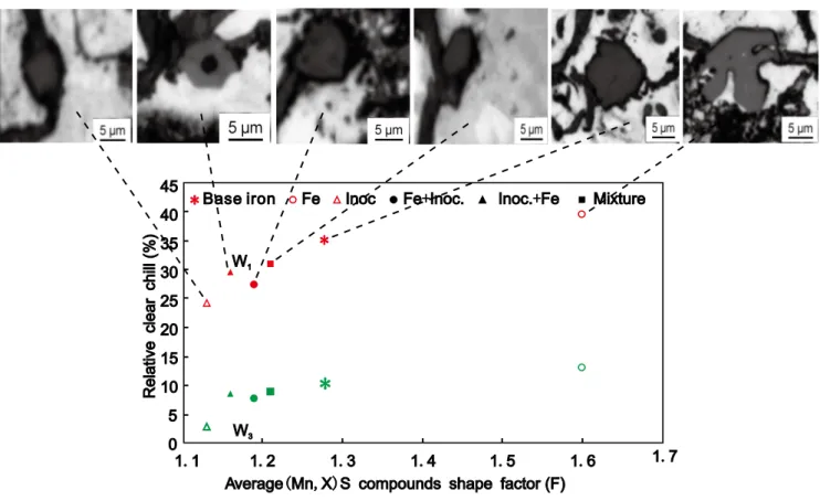
(Mn,X)S compounds, acting as nucleation sites for flake graphite, were analysed for morphology (shape factor) and size characteristics. The shape factor is an aspect ratio (F=L/l) and is deined by the ratio between the maximum L and the minimum l size of the particles, which are more compact at lower F values. The chill tendency of the irons was tested using standard wedges W1 and W3 (ASTM A 367) in resin sand moulds. The relative clear chill (100 Wc/B) refers to the ratio of the measured clear chill Wc found at the apex in a chill wedge, entirely free of any grey areas, to the maximum width of the test wedge, B.
Iron powder additions increased the chill tendency, with single
inoculation showing the strongest graphitizing effect (Fig. 14) [37]
. The double treatment, using both these additions, provided intermediary results, with the lowest chill when inoculation was applied after iron powder additon. It relects the improved properties of (Mn,X)S polygonal compounds as nucleation sites for graphite: in base iron they are larger sized and less compact, becoming irregular polygonal with a complex morphology after iron powder treatment and compact polygonal with the smallest size after inoculation (Fig. 15) [37]
. Iron powder treatment favours austenite dendrite formation, acting as reinforcement for eutectic cells, but accompanied by a negative influence on the graphite nuclei characteristics. A double addition, with
Fig. 14: Average relative clear chill (RCC, %, W1, RM), austenite dendrite area (ADA, %, MM), eutectic cell count (ECC, cm-1
, RM) and (Mn,X)S compounds size (μm, RM) in irons solidiied in resin sand mould (RM) and metal mould (MM)
Fig. 15: Inluence of typical (Mn,X)S compounds resulting from different treatments (25 mm test bar) at different morphologies and shape factor values on relative clear chill of W1 and W3 wedges (ASTM A 367)
solidiied in resin sand moulds
Base iron Treated iron
Fe powder Fe powder inoculation
+ Inoculation 1 RCC
2 ADA 3 ECC 4 Mn X S
. . . .( , ) 70
60
50
40
30
20
10
0
W1
W3 Base iron
*
Fe Inoc Fe Inoc.+ Inoc. Fe+ Mixture*
*
4540
35
30
25
20
15
10
5
0
1 1. 1 2. 1 3. 1 4. 1 5. 1 6. 1 7.
Average Mn X S compounds shape factor (F)( , )
Relative
clear
chill
iron powder and inoculant, appears to benefit both austenite and graphite nucleation, affecting the final structure and chill tendency. The residual beneit of the Fe powder applies to the austenite dendrites and the role of the inoculant is to restore the MnS morphology for chill, eutectic cell and graphite control.
The solidification structure of grey irons at different CE levels is more controlled if these irons are inoculated with a late addition technique, into the mould or the pour basin. Finer eutectic structures in inoculated irons, as a higher count of small sized cells favour is usually associated with less undercooled graphite and fewer free carbides in hypoeutectic irons, and less ferrite in hypereutectic irons. It was determined that the efficiency of 0.05wt.%-0.15wt.% alloy for mould inoculation is comparable to or better than 0.15wt.%-0.25wt.% ladle inoculation additions. Despite having a high carbon content at the eutectic level (CE = 4.4%- 4.5%), eutectic undercooling of electric melt iron having 0.025wt.% S, 0.003wt.% Al is excessively high (31- 33 oC). Under these conditions, inoculation in the mould had a signiicantly greater effect, compared to ladle inoculation, even at smaller inoculant additions (0.20wt.% for hypoeutectic and 0.10wt.% for hypereutectic irons). The Zr,Ca,Al-FeSi alloy appears to be an effective inoculant in low S, low Al, low CE hypoeutectic or slightly hypereutectic grey cast irons, especially with a late inoculation method [2,38]
.
3 Conclusions
(1) Grey cast iron continues to be the most used foundry casting alloy, at 46% of the world total castings production. Important changes have reduced the number of small or inefficient cupolas with a new generation of acid lined coreless induction furnaces (200– 1,000 Hz, > 250 kW/ton specific power). Grey, ductile and compacted graphite irons are produced from the same furnace and many medium wall thickness castings, > 10 mm section size, have been replaced with thinner wall castings, < 10 mm, or <5 mm, typically for the automotive industry.
( 2 ) T h e w o r l d c a s t i r o n f o u n d r y i n d u s t r y c o u l d b e summarized as using electric melting with limited pig iron in a steel and iron scrap charge, containing low S, <0.05wt.% and Al, < 0.005wt.%, but higher residuals (Cr, Mo, Pb, Sn, N), superheating to higher than 1,500 oC for thin wall castings. This combination of unfavourable conditions for solidiication leads to excessive eutectic undercooling causing formation of carbides and undercooled graphite, especially at a lower carbon equivalent.
(3) Electron microscopy examinations revealed that a nucleus for a graphite lake consists of a particle with a body of complex (Mn,X)S sulphide surrounding a nucleus core of a complex oxide.
(4) Three groups of elements are important in grey iron for graphite nucleation with less eutectic undercooling. (a) Strong deoxidizing elements, such as Al or Zr optimally at
0.005wt.%-0.01wt.%, to form very small (< 3 mm) oxide type micro-inclusions to nucleate suitable MnS-type particles to support type-A graphite nucleation. (b) Mn and S to allow MnS type sulphide formation (1-10 mm), which are found to be the most important nucleation sites in commercial grey cast irons. It is important to ensure the control factor (%Mn) × (%S) equals 0.03–0.06. (c) Inoculating elements (such as Ca, Sr, Ba, Ce, La), which act in the irst stage or in the second stage of graphite formation, to improve the capability of (Mn,X)S compounds to nucleate graphite.
(5) The foundry industry needs to sustain formation of (Mn,X)S compounds, to nucleate graphite with less eutectic undercooling, with a high count of small, compact particles having a close crystallographic fit with graphite. The target results of solidifying with less undercooling are type A graphite without type D graphite in a structure with higher eutectic cell count, to avoid carbides especially in thin wall castings.
(6) Three technological steps appear to be necessary to produce high performance grey cast iron via electric melting. (a) Superheat the molten iron to dissolve leftover coarse graphite, loat coarse inclusions and de-activate residual micro-inclusions as unpredictable nuclei for graphite. Excessive superheating, however, will ultimately promote undercooled graphite morphologies with iron carbides. (b) Pre-condition the iron with oxide forming elements, such as Al or Zr, which have been almost eliminated during induction melting. (c) Inoculation with Ca or Sr or Ca + Ba, or Ce or La-FeSi alloys, to control eutectic undercooling and recalescence during solidiication, in response to the base iron quality and casting characteristics.
(7) According to the concept of a coexisting region and non-equilibrium solidiication of grey iron castings, the inal structure of eutectic and hypereutectic grey irons is different compared to equilibrium phase diagram results, mainly due to the beneicial presence of dendritic austenite. The inluence of dendrites on the mechanical properties is similar to the reinforcing steel bars acting as a support frame in concrete, or network of ibres in composites. The greater dendrite amount leads to a stronger cast iron.
(8) Iron powder additions were found important in promoting dendritic austenite, including a high carbon equivalent level, such as eutectic to hypereutectic irons (CE=4.3%-4.5%). This favours austenite dendrite formation, but with a negative inluence on the (Mn,X)S type graphite nuclei characteristics. A double addition of iron powder and inoculant appears to be effective for both the austenite and graphite nucleation, with beneicial effects on the inal structure and chill tendency.
References
[1] A Modern Casting Staff Report. 47th Census of World Casting Production. Modern Casting, 2013(12): 18-23.
[2] Chisamera M, Riposan I, Stan S, et al. Inoculated Slightly H y p e r e u t e c t i c G r a y C a s t I r o n s . J o u r n a l o f M a t e r i a l s Engineering and Performance, 2012, 21(3): 331-338.
Powder Addition on the Solidiication and Structure of Slightly-Hypereutectic Gray Cast Iron. AFS Transactions, 2011, 119: 389-406.
[4] Zhou Jiyang. Colour Metallography of Cast Iron. China Foundry, 2009, 6 (1): 57-69; 6 (3): 255-267.
[5] Riposan I, Chisamera M, Stan S, et al. Three-Stage Model for the Nucleation of Graphite in Grey Cast Iron. Materials Science and Technology, 2010, 26 (12): 1439-1447.
[6] Riposan I, Chisamera M, Stan S, et al. A New Approach on the Graphite Nucleation Mechanism in Grey Irons. In: Proceedings of the AFS Cast Iron Inoculation Conference, Schaumburg, IL, USA, Sept. 29-30, 2005: 31- 41.
[7] Riposan M, Chisamera M, Stan S, et al. Analyses of Possible Nucleation Sites in Ca/Sr Overinoculated Grey Irons. AFS Transactions, 2001, 109: 1151-1162.
[8] Chisamera M, Stan S, Riposan I, et al. Solidiication Pattern of In-Mold and Ladle Inoculated Low Sulfur Hypoeutectic Gray Cast Irons. AFS Transactions, 2008, 116: 641-652.
[9] Riposan I, Chisamera M, Stan S, et al. Role of Lanthanum in Graphite Nucleation in Grey Cast Iron. Key Engineering Materials, 2011, 457: 19-24.
[10] Chisamera M, Riposan I, Stan S, et al. Investigation of Effect of Residual Aluminium on Solidiication Characteristics of Un-Inoculated and Ca/Sr Un-Inoculated Grey Irons. AFS Transactions, 2004, 112: 867-877.
[11] Riposan I, Chisamera S, Stan S, et al. Graphite Nucleants (Microinclusions) Characterization in Ca/Sr Inoculated Grey Irons. International Journal of Cast Metal Research, 2003, 16(1-3): 105-111.
[12] Riposan I, Chisamera M, Stan S, et al. Complex (Mn,X)S compounds - major sites for graphite nucleation in grey cast iron. China Foundry, 2009, 6 (4): 352-355.
[13] Chisamera M, Riposan I, Stan S, et al. Graphite Nucleation Control in Grey Cast Iron. International Journal of Cast Metals Research, 2008, 21 (1-4): 39-44.
[14] Riposan I, Chisamera M, Stan S. Enhanced quality in electric melt grey cast irons. ISIJ International, 2013, 53 (10): 1683– 1695.
[15] Riposan I, Chisamera M, Stan S, et al. High Efficiency Preconditioning of Electrically Melted Grey Cast Irons. In: Proc. 68th World Foundry Congress, Chennai, India, Febr. 2008, Paper 53.
[16] Riposan I, Chisamera M, Stan S, et al. Preconditioning of Electrically Melted Cast Irons. AFS International Iron Melting Conference, January 21-23, 2009, Orlando, Florida, USA. [17] Riposan I, Chisamera M, Stan S, et al. Role of Al, Ti, Zr in
Grey Iron Preconditioning / Inoculation. Journal of Materials Engineering and Performances, 2009, 18 (1): 83-87.
[18] Riposan I, Chisamera M, Stan S, et al. Al, Zr-FeSi Preconditioning of Grey Cast Irons. Materials Science and Technology, 2008, 24(5): 578-584.
[19] R i p o s a n I , C h i s a m e r a M , S t a n S , e t a l . I r o n Q u a l i t y Control during Melting in Coreless Induction Furnace. AFS Transactions, 2009, 117: 423-434.
[20] Riposan I, Chisamera M, Stan S, et al. Identifying chill tendency of cast iron melts by thermal analysis. International Journal of Cast Metals Research, 2013, 26 (3): 152-159. [21] Gundlach R. The 2008 honorary cast iron lecture, Div. 5. AFS
Metalcasting Congress, Atlanta, GA, USA, May 2008, AFS, Paper 08-158.
[22] Riposan I, Chisamera M, Stan S, et al. Chilling properties of Ba/Ca/Sr inoculated grey cast irons. International Journal of Cast Metals Research, 2007, 20(2): 90-97.
[23] Chisamera M, Riposan I, Stan S, et al. Undercooling-Chill Size-Structure Relationship in the Ca/Sr Inoculated Gray Irons (Effects of Calcium and Strontium Inoculation on Undercooling, Chill and Microstructure in Grey Irons of Varying Sulphur and Oxygen Contents). In: Proc. 64th World Foundry Congress, September 2000, Paris, France, Paper No. 62.
[24] Stan S, Riposan I, Chisamera M, et al. Undesirable Graphite Morphologies Incidence in Inoculated Grey Irons. Materials and Technologies, Book Series Advanced Materials Research, ed. by I. Chicinas and T. Canta, Trans Tech Publications, Stafa-Zuerich, Switzerland, 2007, 23: 307-310.
[25] Chisamera M, Riposan I, Stan S, et al. Thermal analysis control of in-mould and ladle inoculated grey cast irons. China Foundry, 2009, 6 (2): 145-151.
[26] Riposan I, Chisamera M, Stan S, et al. The Key Role of Residual Al in Chill Tendency and Structure Characteristics of Un-Inoculated and Ca/Sr Un-Inoculated Grey Irons. In: Proc. 66th World Foundry Congress, Sept. 2004, Istanbul, Turkey, 775- 790. [27] PreseedTM Preconditioner Booklet. ELKEM Foundry Products
Division, 2007, www.foundry.elkem.com.
[28] FoundrisilH 75 Inoculant. ELKEM Foundry Products Division, 2004, www. foundry.elkem.com.
[29] Stan S, Chisamera M, Riposan I, et al. Solidiication Pattern of Un-inoculated and Inoculated Gray Cast Irons in Wedge Test Samples. AFS Transactions, 2010, 118: 295-309.
[30] Rivera G, Calvillo P R, Boeri R, et al. Examination of the Solidiication Macrostructure of Spheroidal and Flake Graphite Cast Irons Using DAAS and ESDD. Materials Characterization, 2008, 59: 1342–1348.
[31] ZIRCINOC Inoculant-Product Data Sheet, ELKEM Foundry Prod., 2007. www.foundry.elkem.com
[32] Ruff GF, Wallace JF. Control of Graphite Structure and Its Effect on Mechanical Properties of Grey Iron. AFS Transactions, 1976, 84: 705–728.
[33] Chisamera M, Riposan I, Stan S, et al. Effects of Iron Powder Addition on the Solidiication Behaviour of Hypereutectic Grey Cast Iron. Key Engineering Materials, 2011, 457: 90-95. [34] Chisamera M, Riposan I, Stan S, et al. Inluence of Iron Powder
Addition on the Structure Characteristics of Hypereutectic Grey Cast Iron. Key Engineering Materials, 2011, 457: 96-101. [35] C h i s a m e r a M , R i p o s a n I , S t a n S , e t a l . S t r u c t u r e
Characteristics of Iron Powder Treated Slightly Hypereutectic Grey Irons. International Journal of Cast Metals Research, 2011, 24 (6): 370-377.
[36] Riposan I, Chisamera M, Stan S,et al. Improving chill control in iron powder treated slightly hypereutectic grey cast irons. China Foundry, 2011, 8 (2): 228-234.
[37] Stan S, Chisamera M, Riposan I, et al. Iron Powder Treated Gray Irons - Critical Shape Characteristics for Graphite Nuclei. Journal of Materials Engineering and Performances, 2012, 21 (8): 1793-1799.
[38] Riposan I, Chisamera M, Stan S, et al. A Comparison of In-mould and Ladle Inoculation Treatments of Low Sulphur Hyper-and-Hypoeutectic Grey Cast Irons. In: Proc. 69th World Foundry Congress, Hangzhou, China, WFO/FICMES, October 16-20, 2010: 342-351.
![Fig. 1: Foundry metallic materials evolution worldwide (a, b,c) and 2012 structure (d) [1]](https://thumb-eu.123doks.com/thumbv2/123dok_br/16431197.196001/2.892.90.790.409.877/fig-foundry-metallic-materials-evolution-worldwide-b-structure.webp)
![Fig. 7: Graphite nuclei [(Mn,X)S compounds] characteristics and resulted graphite particles morphologies in un-preconditioned (R) and Ti, Al or Zr preconditioned and Sr-FeSi inoculated grey irons](https://thumb-eu.123doks.com/thumbv2/123dok_br/16431197.196001/7.892.136.754.491.936/graphite-compounds-characteristics-particles-morphologies-preconditioned-preconditioned-inoculated.webp)