*e-mail: [email protected]
The Mechanism of Changes in the Surface Layer of
Grey Cast Iron Automotive Brake Disc
Adam Polak*, Janusz Grzybek
Cracow University of Technology, Institute of Automobiles and
Internal Combustion Engines, Poland
Received: July 19, 2004; Revised: July 25, 2005
The aim of the study was to create a model, describing the run of tribological processes in the surface layer of grey cast iron automotive brake discs. Grey cast iron discs mating with non-asbestos organic brake pads were chosen for the investigations, as the most widely used materials in car brakes. Samples for surface analysis were prepared from disc operating in stand and road conditions. Stand tests were pin-on-disc kind. Operating parameters for the stand tests were chosen on the basis of results of our earlier research. Topography of brake disc surface was evaluated by surface roughness measurements. The surface layer was examined with use of metallography and scanning electron microscopy. In order to differentiate structures of grey cast iron brake discs SE and BSE modes were used in scanning electron microscopy. Chemical investigations of samples were done by X-ray analysis linked with SEM. Studies showed influence of grey cast iron structures on tribological processes taking place in a brake friction pair. The surface layer of grey cast iron discs was described and features and functions of separated structures were presented. On the basis of the obtained results a physical model of friction mechanism was created. Special attention was paid to the influence of graphite on the run of tribological processes and mechanism of compaction and removal of wear debris.
Keywords:grey cast iron, disc brakes, tribology
1. Introduction
In spite of appearance of new materials, (carbon composites, me-tallic matrix composites, ceramic composites1-3) grey cast iron is the most widely used material for automotive brake discs4. Advantages of grey cast iron: low cost of production and good tribological properties are the main reason for use of this material. Technology of cast iron has been improved during the last years and new kinds of cast iron were developed. However, discs of automotive brakes are produced of grey cast iron, with graphite in the form of flakes6,7. Authors posed the question about the mechanism of friction between a grey cast iron disc and brake pads made of non-asbestos organic friction material. This problem is often under investigation5,7-9, and current is focused on the role of grey cast iron structures in wear processes and possibility of influence on frictional characteristic.
2. Materials and Methods
Grey cast iron disc mating with non-asbestos organic friction materials, was taken into consideration. Samples for surface layer investigations come from two kinds of tests: pin-on-disc test machine (Figure 1) and in-field tests (Figure 2). Testing conditions were: 0 to 4 MPa for pressure between disc and pad, 0 to 10 m/s for sliding speed and up to 400 °C for operating temperature. Surface layers of brake disc and brake pad were investigated by optical and scanning electron microscopy (Philips XL30) in SE and BSE modes. Chemical analysis was made by use of energy dispersive X-ray spectrometer LINK ISIS. Three modes of analysis were used: at point, linescan and mapping.
3. Results and Discussion
Grey cast iron discs have a ferritic and pearlitic metallic structure and graphite in the form of flakes. Analysis of the discs from different producers and from different series show that graphite flakes vary from A to E shape7. The most important is the fact, that the operating
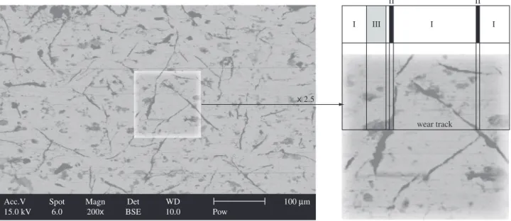
surface of the brake disc makes a cross-section of graphite flakes. The size and position of graphite flakes depends on the parameters of casting and cooling. Figure 3 presents a typical operating surface of a grey cast iron brake disc.
The main target of the car brakes is to dissipate energy, at low wear of brake disc and brake pad. To diminish the wear of friction elements energy should be dissipated in processes which do not conduct to material decohesion and removal. However, decohesion will always appear, with intensity depending on material properties and operating conditions. Minimising the wear of materials in case of decohesion is possible by leaving the wear debris in the friction zone.
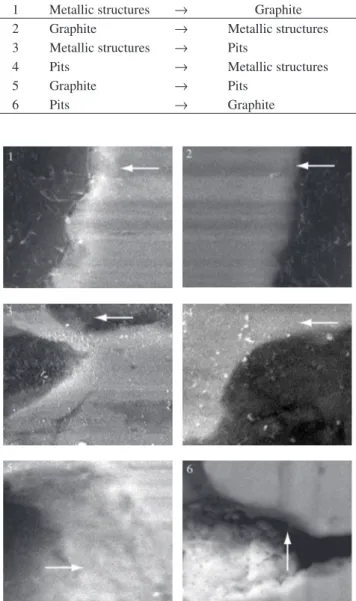
The main feature of a grey cast iron disc operating surface is non-homogenity of material. Wear track area could be divided into metallic structures and graphite flakes. This differentiate the character of tribological processes. During operation in road conditions third form appears on the wear track area, as a result of friction processes. These are the pits, which originate from removal of the graphite or as a result of corrosion. A single wear track can be divided as it is presented in Figure 3. From the tribological point of view there exist three different zones (Table 1) and six kinds of borders (boundaries) between them (Table 2). Figure 4 presents the six kinds of borders.
p 7
8
1
2
3
+ 12 V
4 5
6
(a)
(b)
Figure 2. In-field measurement system: diagram a) 1-PC computer, 2-Spider 8 data acquisition device, 3-voltage inverter, 4-brake disc, 5-brake pad, 6-pres-sure sensor, 7-thermocouple (J), 8-speed sensor; and b) view of brake disc and caliper with thermocouple.
2 3 1
4
P 2 1
5
6
W
(a)
(b)
Figure 1. Pin-on-disc test machine: diagram a) 1-brake disc, 2-sample (fric-tion material), 3-thermocouple (J), 4-force sensor (HBM C2), 5-Spider 8 data acquisition device, 6- PC computer; and b) view of wear track.
Acc.V Spot Magn Det WD 100Mm
15.0 kV 6.0 200x BSE 10.0 Pow
x2.5
wear track
I III I I
II II
Table 1. Zones of the brake disc operating surface.
Zone I Metallic structures Zone II Graphite flakes
Zone III Pits
Table 2. Borders between zones of the brake disc operating surface (concern-ing the direction of change).
1 Metallic structures → Graphite 2 Graphite → Metallic structures 3 Metallic structures → Pits
4 Pits → Metallic structures
5 Graphite → Pits
6 Pits → Graphite
Figure 4. Borders between zones of the brake disc operating surface; arrows correspond to the direction of sliding speed.
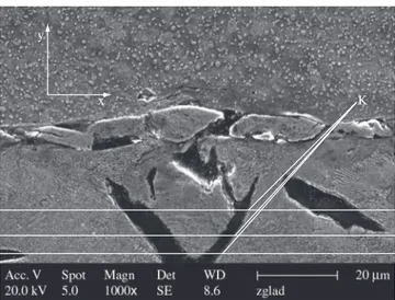
Figure 5. Plastic deformations on the operating surface of brake disc, SEM image, SE mode.
Figure 6. Removal of graphite from its nest; SEM image, SE mode.
graphite is removed all at once, leaving empty nest - Figure 7. Zone III, the pit, is the place of material storage, both wear debris and external impurities coming from the environment - Figure 8. Special storage functions of the pits could occur in two cases. First one, when pits store products of corrosion, when corroded brake operates oxidized layers are removed. However, the majority of corrosive products are stored on the brake pad. Second one, when storage function of pits lets the brake to operate in wet conditions, when water can be moved from the operating surface into the pits allowing frictional contact.
Run of tribological processes depends on properties of grey cast iron. Fundamental are: shape, size, position and distribution of free
graphite and corrosive properties of grey cast iron. The first influ-ences the way of graphite removal and parameters of pits. The second influences tendency of pit creation and development.
From the tribological point of view the most interesting are the borders between the distinguished zones. In respect to different
functions of the brake disc zones defined above, borders between them are the places where the change of tribological processes takes place. It is often connected with intermittent contact between mating elements. If the wear is treated as the removal subsequent layers of material, the position of border between metallic structure and graphite flake depends only on the shape of graphite - Figure 9. However this assumption could not be fulfilled in real conditions. In the surroundings of the border strong plastic deformation, material decohesion and oxidation occur.
Investigations pointed out some rules governing the change of the position of borders. The main factor is the shape of graphite flake. It is the start point for setting of border position. Further changes depend on tribological processes. The favoured direction of the border move-ment is the direction of sliding speed. Automotive disc brakes operate in both direction of revolution. However, pressure, sliding speed and temperature achieved during reverse motion of the car are relatively low in comparison to those, which exist during forward movement. Observation and analysis showed, that operating surfaces of brake friction pair elements are formed when car moves forward.
The direction of sliding speed, as conducted investigations showed, is the basic factor governing the changes in the surround-ings of borders between zones of the brake disc operating surface. It is clearly visible on the example of plastic deformations. There are
differences in forming of the coming-in and coming-out border. As it is presented in the Figure 10, material is moved in the direction of sliding speed, which results in overlaping of the material on the graphite or on the pit - (detail A - coming-in edge) and compressing or wearing out of the material - detail B -coming-out edge.
Forming of borders depends also on the position of graphite in relation to the operating surface. There are a few cases (Figure 11), a - graphite flake perpendicular to operating surface; b - tilted toward sliding speed, and c - tilted against sliding speed.
Strains are connected with stiffness of the sub-surface layers. In case b, stiffness of the coming-in edge is lower than in the case c and plastic deformations are more probable. On the other hand, the coming-in edge in case c is stiff and plastic deformations are not so probable. All of the arrangements of graphite flakes mentioned above
x y
K
Figure 9. Positions of K points (borders between metallic structures and graphite flake) as a function of graphite shape.
Figure 8. Storage of wear debris in the pit; SEM image, BSE mode.
Figure 10. Overlaping and compressing of material in the zone of border.
V V V V
(a) (b) (c) (d)
They can also originate from corrosive processes. Regardless of their origin, they are places for storage of wear debris or contaminations. Storage function is very important for brake tribology due to its role in formation of the third body.
At the borders between zones tribological processes change their character. A proper operation of brake disc is possible when balance between the distinguished zones is maintaned.
4. Conclusions
Run of tribological processes in the grey cast iron brake disc and NAO brake pad is strongly influenced by structure of grey cast iron.
Each of the three distinguished zones of the brake operating surface has its own function in the tribology of the brake friction pair and those functions were determined.
Borders, between zones of the brake disc operating surface are the places where change in the run of tribological processes takes place.
Position, shape, and size of graphite flakes plays a major role in the formation of the disc brake operating surface.
References
1. Blanco C, Bermejo J, Marsh H, Menendez R, Chemical and physi-cal properties of carbon as related to brake performance. Wear. 1997; 213(1-2):1-12.
2. Carbon Brakes, Technical Documetantion of Messier-Bugatti, Zone Aéronautique Louis Breguet 78140 Vélizy-Villacoublay-France, 1999.
3. Hecht Basch R, Fash J, Hasson R, Dalka T, McCune R, Kaufold R. Initial dynamometer and laboratory evaluations of thermally sprayed aluminium brake disc. In: Barton D, Earl S, Brakes 2000, Proceedings of: International Conference on Automotive Braking – Technologies for the 21st century, Leeds, UK, 2000 July 11-12; p. 4775-4781.
4. Grzybek J, Analiza technologiczno-materiałowa tarczowych mechaniz-mów hamulcowych (in polish)/Technological and material analysis of disc brakes, Teka Komisji Naukowo-Problemowej Motoryzacji PAN Kraków, Zeszyt, 2000; 20:121-130.
5. Polak A, Grzybek J, Friction processes in disc brake – brake pad couple, Proc. of SAE International off-Highway Congress, CONEXPO-CON-AGG, Las Vegas, 2002, Transmission and Driveline Systems for off Highway, SAE Technical Paper Series 2002-01-1484. p. 101-110.
6. Graphite shape from start to end, Sinter Cast. 2002. Regal House 70 London Road, Twickenham Middlesex, UK, www.sintercast.com.
7. Krause DE, Gray Iron – a unique engineering material, ASTM STP 455, American Society for Testing and Materials, Philadelphia. 1969. p. 3-28.
8. Berns H, Comparison of wear resistant MMC and white cast iron. Wear. 2003; 254(1-2):47-54.
9. Cho MH, Kim SJ, Basch RH, Fash JW, Jang H, Tribological study of gray cast iron with automotive brake linings: The effect of rotor microstructure,
Tribology International. 2003; 36(7):537-545.
10. Hecht RL, Dinwiddie RB, Wang H. The effect of graphite flake morphol-ogy on the thermal diffusity of grey cast iron used for the automotive brake discs. Journal of Material Science. 1999; 34(19):4775-4781. C
C
Fe-C Fe-C ZFe-C Fe-C Z
C B A DISC Ra C
Figure 13. Physical model of the grey cast iron brake disc: Fe-C - metallic structures, C - graphite flake, Z - pits, black arrows - removal of graphite, brown arrows, compaction and storage of wear debris.
Figure 12. Oxidation in the area of borders, X-ray analysis (linescan).
Job: analizy Length: 36.27 Mm
Label: ptx 1400 (4 Dec 01 00:29:28) SE, 139241
Cka, 6
Oka, 12
Feka, 270 ~ 20 Mm
give stepped dosing of graphite for the friction zone. There is also a seldom case (Figure 11d), when the graphite flake is parallel to the operating surface. Positioning of graphite flake in that way is not beneficial, due to a large occupied surface.
Simultaneously, in the area of borders, where a larger surface can react with oxygen and mechanical processes appear, oxidation takes place. Chemical analysis, (linescan), shows higher oxygen content - Figure 12. Oxidized zones allow for a faster run of mechanical processes.
On the basis of conducted research a physical model of tribologi-cal processes was proposed. Operating surface of grey cast iron brake disc was divided into distinguished zones and tribological functions were ascribed to them - Figure 13.