Gas Hold-Up, Mixing Time and Circulation Time in Internal
Loop Airlift Bubble Column
Ali Abdul Rahman–Al Ezzi*a,b
Ghazi Faisal Najmuldeena
a
Faculty of Chemical & Natural Resources Engineering/ University Malaysia Pahang
b
Department of Chemical Engineering, University of Technology/ Baghdad, Iraq
Abstract
The effects of superficial gas in the riser (Vgr) and liquid phase properties on the gas hold-up(ɛg) , mixing time (Tm) and circulation time (TC) were studied in 8 liter internal air lift loop reactor (down comer-to-riser cross-sectional area ratio = 0.249). Air was used as a gas phase. Water and four aqueous solutions of 10% concentration methanol, ethanol, (were used to simulate the behavior of non-coalescing organic liquids) 50% glycerol and 2% Carboxy Methyl Cellulose (CMC) were used to simulate the behavior of coalescing viscous liquids. Polyethylene-non-porous-solid particles with a concentration of (50) Kg/m3 were used as solid phase. Superficial gas velocity varied from 0.01 m/s to 0.1 m/s and air dispersed into the center of the draught tube by using a porous gas distributor. The results showed that (εg) increased with increasing gas velocity and coalescence inhibition of liquid, while Tm and Tc decrease with increasing gas velocity. It was found that increasing liquid viscosity and coalescence reduces (εg) but increases (Tm) and (Tc). The gas holdup was correlated with dimensionless groups and independent parameter with correlation coefficient is 0.967, the following correlation is obtained.
K
S S m
L L
L n
L L g g
C
g
V
A
34
Keywords
: Airlift reactor; mixing time; Circulation time; Liquid-phase propertiesI.
Introduction
Airlift reactors (ALRs) are suitable for many different processes. They are mainly used as bioreactors in fermentation processes and in the biotransformation of many substances [1, 2]. In wastewater treatment ALRs are increasingly being developed [3-7]. Airlift loop reactors find extensive applications in many areas of chemical engineering, especially for homogeneous as well as heterogeneous single and multiphase systems due to their simple construction and operation, directed circulation flow, good mixing and favorable ratio of interfacial area of energy dissipation rate per unit volume, low investment, operational costs and relatively lower power requirements [8]. The mixing time and circulation time are important hydrodynamic characteristics of airlift reactors [9].The liquid circulation velocity effects on the residence time of gas, mass transfer and mixing time Tm. Studies showed that liquid circulation velocity was affected by the gas flow rate and geometric parameters of the column.[10-12] Liquid circulation occurs due to the difference in hydrostatic pressure or density between the riser and down comer. When gas flow rate increases, the liquid velocity also increases, thereby entraining most of the bubbles from the riser in to the down comer. This will reduce the difference in
hydrostatic pressure (compromising the liquid velocity). In general, a higher liquid velocity reduces the residence time of the bubbles in the riser and down comer, as it encourages the recirculation of gas through the down comer and back to the riser. (Weiland et al.[13], Chisti et al. [14], Choi et al. [15], Petrovic and Posarac[16], Bentifraouine et al. [17], and Yazdian et al. [18]) investigated the effects of operating parameters on the hydrodynamic behavior of concentric draft-tube type airlift reactors. They observed a decrease in the mixing time with the decrease of the cross sectional area ratio (Ad/Ar). They also observed the mixing time increases with increasing the top and bottom clearances [13, 18]. The top and bottom clearances do exert an important effect on gas holdup, mixing time, circulation time, and mass transfer. The analysis and description of the behavior of an ALR involve the study of characteristics such as mixing and circulation time. It is necessary to get information about the interaction between these parameters and the operation variable as well as the design variables, in order to make a correct design of the airlift reactor [19]. Many researchers (Camarasa et al., [20]; Kelkar et al., [21]; Posarac et al., [22]) reported that the addition of small quantities of aliphatic alcohols increased the gas holdup, in comparison to pure water, in bubble columns (BCs), continuous BCs,
draft tube airlift reactors (DT-ALRs), Along with the changes in the gas holdup, the induced liquid velocity in ALRs is also affected by alcohol addition. Although a large number of investigations contributed to the knowledge of the effect of various parameters on hydrodynamics and mass transfer characteristics in ALRs, available information frequently showed wide variations and conflicting claims. Molina et al. [23] characterized mixing in a split cylinder airlift bioreactor (Ad/Ar ratio of 1, sucrose solution with viscosity variations of 1.54±19.5×10⁻³Pa.s, and Vgr of
0 ± 0.039 m/s). It was reported that viscosity had no influence on circulation time, which contradicted the theory (increase in viscosity reduces flow as a result of resistance). According to them, the driving force of circulation has increased with increasing viscosity for any gas flow rate. This was due to the fact that as viscosity increased more bubbles were coalesced with a magnitude of smaller bubbles, where most of these large bubbles were disengaged at the top and smaller ones went through the down comer. This achieved a higher driving force for liquid circulation. Viscosity had little effect on mixing time, which suggests that mixing time was affected by differences in velocities between the gas and liquid phases. Merchuk et al. [24] carried out an extensive study in a concentric tube reactor with seven different spargers (four cylindrical and three porous plates) of varying pore sizes using sea water and NaCl. They reported that the sparger pore size had an impact on the gas holdup and liquid recirculation. The smaller the pore sizes the higher the gas holdup which implied a decrease in the liquid circulation velocity. At a higher gas velocity, mixing time was independent of sparger geometry although the geometry of the sparger and pore size had an impact at a low gas velocity. Finally, the holdup was affected by coalescing and not by the geometry of the sparger used. Miron et al. [25] tested mixing in a bubble column and airlift (split cylinder and draft tube) with a dispersion height of 2 m and working volume of 0.06 m3 using water and seawater. They reported that, at any gas flow rate the values of mixing parameters in the two fluid media were identical. In all reactors mixing time decreased with increased superficial gas velocity. However, the bubble column gave the shortest mixing time due to the bulk flow as opposed to the airlift where circulation was in a cyclic motion impeding the bulk flow. The contradiction is regularly attributed to the difference in the reactor geometries, experimental conditions and experimental techniques. However the present knowledge suggests that this contradiction is brought about by some complicated phenomena taking place in ALR, such as the bubble size distribution, internal liquid circulation, etc. [26-30]. The purpose of this study is to clarify experimentally the effects of the gas velocity and liquid phase properties (coalescing) on gas hold up (ɛg), mixing
time (Tm) and circulation time (Tc) in a solid suspends
concentric tube airlift loop reactor when down comer-to-riser cross-sectional area ratio = 0.249 and the air is dispersion into the center of the riser by using a porous gas distributor.
II.
Experimental Section
distributor in Fig (1.c) was constructed from a ceramic material and the type is a multi hole tuyere. The distributor has an equivalent pore diameter of 0.15 mm and a free section of 80%.
(a)
(b)
(c)
Figure 1: (a) Experimental-Apparatus; (b) Column and (c) Gas distributor
Table 1: Physical-properties for pure liquids at T = 20 oC
(kg/m3) 103
µ (CP)
σ (dyn/c m)
νL
(cm2/s e Water 0.998 1.002 72.86 1.004 Methanol 0.791 0.584 22.61 0.738 Ethanol 0.789 1.200 22.27 1.520 Glycerol 1.261 1.005 6304 0.796 CMC 1.008 K=0.01
2 ps.sn n=0.8
73 1.23
The solution of CMC (carboxy methyl cellulose) shows non Newtonian, pseudo plastic behavior, which can be described by the power law of Ostwald and deweale:
t = K ɤn Where:-
K: Ostwald factor (consistency index) n: flow behavior index
ɤ: shear rate 1/sec T: shear stress µeff= ɤn-1
where µeff: effective liquid phase viscosity Pa.s Y = 5000 Vg [31]
Where Vg: gas velocity m/sec.
Table 2: Physical properties for mixtures used with various concentrations at T=20oC
(kg/m3)1 03
µ (CP)
σ (dyn/ cm)
νL
(cm2/sec)
Water-Methanol 10%
0.9815 0.795 22.63 0.8226
Water-Ethanol 10%
0.981 0.910 22.64 0.9400
Water-glycerol 50%
1.126 6.00 64 0.8905
Water-CMC 2%
1.009 K=1.320 Pasnn=0. 5
2.1 Gas Hold Up (ɛg) and Solid Hold Up (ɛs)
Measurements
The average gas hold up εg was calculated from the equation (1) usingthe data of the clear - liquid height (HL) and the height of the aerated liquid (HF) which was determined by visual observation:
i o
F
L F g
S
V
H
H
H
/
(1)
V
i/
S
o
In Eq (1) is a correction term for the volume of the draft tube [32] the solid-hold-up was calculated from the equation(2).Using the date of static liquid height (HF) and the height of slurry after adding solid particles (HF/):F L F s
H
H
H
(2)The experimental gas hold up was found by measuring the difference between initial liquid height and final liquid height. Since it was rather difficult to read directly the level of the aerated liquid the values of gas hold up thus obtained probably involves an error of about 5%, established via repeated measurements.
2.2 Mixing Time Measurement
Visual monitoring of acid - base reaction between HCL and NaOH was chosen among the various methods presented in the literature for measuring mixing time.
HCl + NaOH NaCl + H20
Methyl red was used as the indicator of the above neutralization reaction. Twenty milliliters of 2N NaOH with about 30 ml of methyl red indicator were added to the liquid which turned deep yellow. When the liquid was not deep colored, the further methyl red indicator was added. After setting the operating conditions and at time = 0, an amount slightly in excess of the stoichiometric quantity of 2N HCl solution (about 21 milliliters), placed in a small beaker, was added to the surface of the liquid near the wall [33, 34]. The mixing time was taken at the time necessary to obtain a complete color change to red. This technique is reliable [33, 34]. An average of three measurements under the same conditions were taken. The technique has been used by a number of workers [see for example the most valuable papers of Brennan and Lehrer [33] , Hiby [35] and Mavros, P., [34].
2.3 Circulation Time Measurement
The method proposed by (Lu et al., [36]; Guy et al., [37]was used to determine the circulation time. The circulation time is the time between two successive crossing of tracer particle, in the same direction, through a chosen plane. The reference plane
was chosen to be the medium - height plane and the particle was a colored tracer (black) of foam of about 5 mm diameter, which becomes totally impregnated when immersed in the liquid and thus reaches the liquid density. The black tracer particle was clearly visible in liquids, an average of five measurements under the same conditions were taken.
III.
Gas hold up result
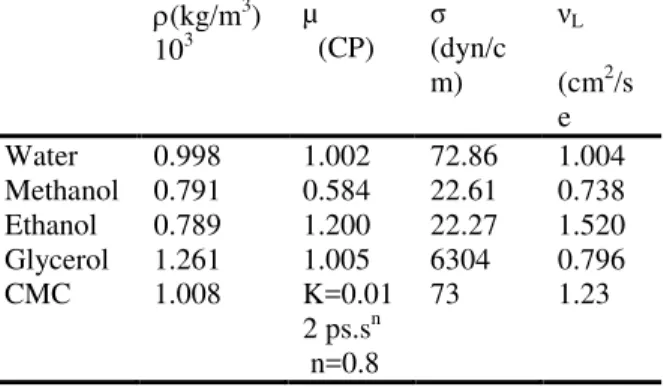
Figure 2:Effect of gas velocity on gas hold up with different liquid phase systems.
Figure 3: Effect of gas velocity on gas hold up for water, water-methanol and water-ethanol systems.
Figure 4:Effect of gas velocity on gas hold up for water, water-glycerol and water-CMC systems.
3.1 Gas Holdup Correlation
Dimensional analysis was used to correlate gas hold-up with gas velocity and liquid properties. It was assumed that (ɛg) is a function of the following factors:-
f
g
(V
G,
L,
L,
L,
g
)
(3) In case of using solid particles, the factors (CS and S) will be added to the equation above.)
,
,
,
,
,
,
(
G L L L S Sg
f
V
g
C
(4) It is possible to predict that there must be a functional relationship between these variables and that the relationship is independent of the units of measure. The simplest form for a function is one in which the variables are multiplied or divided by one another in such a way that dimensionless groups arise. From experimental results, it can be seen that (ɛg) increases with increasing (
V
g) and decreases withincreasing (µL and
L), so the resulting correlation applied to predict the gas hold-up for air-water system. The equation will have the formK S S m L L L n L L g g
C
g
V
A
43(5)
The statistical analysis was performed using the capabilities of SPSS software to obtain the values of A, n, m and k.
The final correlation is given by:-
805 0 189 0 3 4 408 0 242 0 . . . . S S L L L L L g g C g V (6)
Where: -
L L gV
= Capillary Number
3 4 L L Lg
= Morton Number
A= 0.242 n= 0.408 m= 0.189 K= 0.805 R2= 0.967
IV.
Mixing time and circulation time
results
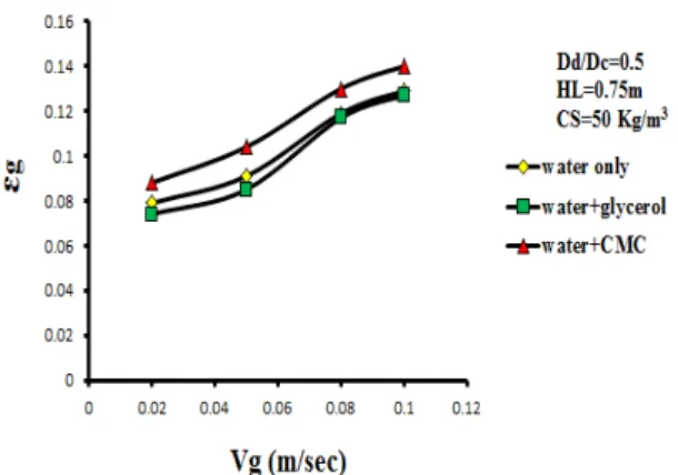
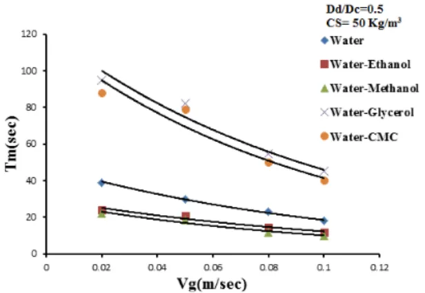
increases with the start of gas circulation since bubbles which coalesce in the annular space rise against the liquid flow and therefore considerably speed up the mixing process. The intensive mixing in the deflection zones is caused by differences between velocities in the up and down flow zones. In the top zone, mixing is intensified by the formation of a ring vortex above the draft tube. Figures (5), (6), (7), (8), (9) and (10) shows the effect of gas velocity for different liquid phase systems (water, ethanol, methanol, water-glycerol and water-CMC) on Tm and TCwhen the down comer-to-riser cross-sectional area ratio = 0.249. The figures reveal the following:
(i) The mixing time and circulation time for [water-CMC, water-glycerol, figures (7) and (10)] decreases with increases gas velocity. Because of increases viscosity (water-glycerol system which has a viscosity 6 times that of pure water, table A2), therefore the Tm and TC are larger than that in water. This is in agreement with literature (e.g. Franz et al [45]).
(ii) In general the overall effect of presence of alcohols [water-methanol, water-ethanol, figure (6)] is that increases the mixing time. These systems represents a strongly coalescence inhibiting systems this leads to a higher gas hold-up in the annular space which decreases the hydrostatic driving force for liquid circulation, therefore the effect of gas velocity on liquid circulation time is approximately similar to that for water figure (9). This is in agreement with the literature (e.g. Pandit and Joshi [46]).
(iii)At high values of gas velocity about 0.1 m/sec the Tm and TC for different systems become equal because of the liquid velocities approach a constant value.
Figure 5:Effect of gas velocity and solid content on mixing time for different liquid phase system.
Figure 6:Effect of gas velocity and solid content on mixing time for (water, water- methanol,
water-ethanol) systems.
Figure 7:Effect of gas velocity and solid content on mixing time for (water, water- glycerol,
water-CMC) systems.
Figure 8:Effect of gas velocity on circulation time for different liquid phase system.
Figure 9:Effect of gas velocity and solid content on circulation timefor (water, methanol,
Figure 10:Effect of gas velocity and solid content on circulation timefor (water,water- glycerol,
water-CMC) systems.
V.
Conclusions
For the present study the following conclusions were made:-
1. The gas hold-up increase with increasing gas velocity for Vg ≤ 0.1 m/sec and decrease with increasing liquid surface tension in 8 liters air lift loop reactor in the presence of alcohol and suspended solid particles (polyethylene)and the down comer-to-riser cross-sectional area ratio = 0.249.
2. The mixing time and circulation time decreases with increasing gas velocity for Vg ≤ 0.l m/sec in the air lift loop reactor when the down comer-to-riser cross-sectional area ratio = 0.249, and the reactor volume equal to 8 liters.
3. The circulation velocity decreases with increasing viscosity and coalescence inhibition of the liquid phase.
4. Higher viscosities enhance internal friction losses, while stronger coalescence inhibition results in a higher gas hold-up in the annular space which decreases the hydrostatic driving force for liquid circulation.
Nomenclature
a Specific gas-liquid interfacial area based on aerated liquid volume m-1
Ci Concentration of dissolved oxygen at any time
p.p.m
C0 Initial Concentration of dissolved oxygen p.p.m
CSa Saturated concentration of dissolved oxygen
p.p.m
CS Solid particle concentration KG/m 3
DC Column diameter
Di Diffusivity of oxygen in solution m2/sec
DL Axial dispersion coefficient (liquid) m2/sec
g Acceleration of gravity m/sec2 HL Static slurry height (m)
HF Level of aerated slurry (m)
F
H Level of liquid phase+ solids (m)
KL Liquid phase mass transfer coefficient (m.s-1)
KLa Overall mass transfer coefficient, based on
aerated slurry volume. (Sec-1) Sc Slurry column
t Time (min)
Vg Gas velocity (m/sec)
Greek letters
εg Gas hold up
εs Solid hold up
ρL Liquid phase density kg/m3
ρS Solid phase density kg/m3 L Liquid phase viscosity(Cp)
L Kinematic viscosity of liquid phase (cm2/sec)
σL Liquid phase surface tension dyne/cm
Subscripts G gas L Liquid
References
[1] Sánchez Mirón, A., Cerón García, M.C., García Camacho, F., Molina Grima, E.and Sarkar, S., Kaustubha, M. and Meikap, B.C, Hydrodynamic modeling of a novel multi-stage gas–liquid external loop airlift reactor. Chemical Engineering Journal., 2008, 145: 69–77.
[2] Acién Fernández, F. G., Fernández Sevilla, J. M., Sánchez Pérez, J. A., Molina Grima, E. and Chisti, Y, Airlift-driven external-loop tubular photo bioreactors for outdoor production of microalgae: assessment of design and performance. Chemical Engineering Science.,2001,56:2721–2732. [3] Frijters, C.T.M.J., Eikelboom, D.H., Mulder,
A. and Mulder, R, Treatment of municipal wastewater in a CIRCOX® airlift reactor with integrated denitrification. Water Science and Technology.,1997,36 (1): 173–181. [4] Heijnen, J.J., Hols, J., Van der Lans,
in the gas recirculation regime. Chemical Engineering Science.,1997,52 (15):2527– 2540.
[5] Van Benthum, W.A.J., Van Loosdrecht, M.C.M. and Heijnen, J.J, Process design for nitrogen removal using nitrifying biofilm and denitrifying suspended growth in a biofilm airlift suspension reactor.Water Science and Technology.,1997, 36 (1):119–128.
[6] Van Benthum, W.A.J., Van der Lans, R.G.J.M., Van Loosdrecht, M.C.M. and Heijnen, J.J, The biofilm airlift suspension extension reactor-II: three-phase hydrodynamics. Chemical Engineering Science.,2000, 55 (3): 699–711.
[7] Beun, J.J., Van Loosdrecht, M.C.M. and Heijnen, J.J, Aerobic granulation in a sequencing batch airlift reactor.Water Research.,2002, 36 (3): 702–712.
[8] Merchuk, J. C. and Siegel, H, Chemical Technology and Biotechnology.,1988, 41: 105.
[9] Prokop, A., Erickson, L.E., Fernandez, J. and Humphrey, A.E, Design and physical characteristics of a multistage, continuous tower. Journal of Bioscience and Bioengineering.,1969, 11:945–966.
[10] Gouveia ER, Hokka CO, Badino jnr AC, The Effects of geometry and operational conditions on gas holdup, liquid circulation and mass transfer in anairlift reactor. Brazil J. Chem. Eng., 2003, 20: 363-374.
[11] Luo HP, Al-Dahhan MH , Macro-mixing in a draft tube airlift bioreactor. Chem. Eng. Sci., 2008, 63: 1572-1585.
[12] Mehrnia MR, Towfighi J. Bonakdarpour B, Akbarnegad MM , Influence of top-section design and draft-tube height on the performance of airlift bioreactors containing water-in-oil microemulsion. J. Chem. Technol. Biotechnol., 2004, 79: 260-267. [13] Weiland, P, Influence of draft tube diameter
on operation behavior of airlift loop reactors. German Chemical Engineering.,198, 47: 374–385.
[14] Chisti, M.Y., Kasper, M. and MooYoung, M, Mass transfer in external loop airlift bioreactors using static mixers. The Canadian Journal of Chemical Engineering.,1990, 68(1): 45 –50.
[15] Choi, K.H., Han, B.H. and Lee, W.K, Effect of horizontal connection pipe length on gas hold up and volumetric oxygen transfer coefficient in external loop airlift reactor. Hwahak kwa hwahak konghak.,1990, 28:220. [16] Petrovic, D.L. and Posarac, D, Prediction of mixing time in airlift reactors. Chemical
Engineering Communications.,1995, 133:1– 9.
[17] Bentifraouine, C., Xuereb, C. and Riba, J.P, An experimental study of the hydrodynamic characteristics of external loop airlift contactors. Journal of Chemical Technology and Biotechnology.,1997, 69:345–349. [18] Yazdian, F., Shjaosadati, S.A., Nosrati, M.
and Vasheghani F. E, Study of geometry and operational conditions on mixing time, gas holdup, mass transfer, flow regime and biomass production from natural gas in a horizontal tubular loop bioreactor. Chemical Engineering Science.,2009, 64(3): 540–547. [19] Michael, J.C., and Gluz, M, Bioreactors,
Airlift Reactors, in the encyclopedia of bioprocess technology, John Wiley & Sons Inc., USA, 1996,p.320.
[20] Camarasa, E., Vial, C., Poncin, S., Wild, G., Midoux, N. and Buoillard, J, Influence of Coalescence Behaviour of the Liquid and of Gas Sparging on Hydrodynamics and Bubble Characteristics in a Bubble Column. Chemical Engineering and Processing.,1999, 38: 329–344.
[21] Kelkar, B. G., Godbole, S. P., Honath, M. F. and Shah, Y. T, Effect of Addition of Alcohols on Gas Holdup and Backmixing in Bubble Columns. AIChE J.,1983, 29: 361– 369.
[22] Posarac, D. and Tekic, M. N, Gas Holdup and Volumetric Mass Transfer Coefficient in Bubble Columns with Dilute Alcohol Solutions. AIChE J.,1987, 33: 497–499. [23] Molina E, Contreras A, Chisti Y , Gas
holdup, liquid circulation and mixing behaviour of viscous Newtonaian media in a split-cylinder airlift bioreactor. Trans. Inst. Chem. Eng., 1999, 77: 27-32.
[24] Merchuk JC, Ronen M, Giris S, Arad MS,Light-dark cycles in the growth of the red microalga. Biotechnol. Bioeng., 1998, 59: 705-713.
[25] Miron, A.S., Camacho, F.G., Gomez, A.C., Grima, E.M., and Chisti Y , Bubble column and airlift photo bio rectors for algal culture. AIChE J., 2000, 46: 1872-1887.
[26] Samuel, T., Arnaud C. and Alain L, Global modeling of a gas–liquid– solid airlift reactor. Chemical Engineering Science.,2005, 60: 5991–6003.
[28] Wei, Y., Wang, T., Liu, M. and Wang, Z, Bubble circulation regimes in a multi-stage internal-loop airlift reactor. Chemical Engineering Journal.,2008, 142: 301–308. [29] Giovannettonea, J.P., saib, E.T. and Gulliver,
J.S, Gas void ratio and bubble diameter inside a deep airlift reactor. Chemical Engineering Journal.,2009,149: 301–310. [30] Zhonghuo, D., Wang, T., Zhang N. and
Wang, Z, Gas holdup, bubble behavior and mass transfer in a 5m high internal-loop airlift reactor with non -Newtonian fluid. Chemical Engineering Journal., 2010, 160:729–737.
[31] Nishikawa,M.;Kato,H.; Hashimoto,K, Ind.Eng.chem.process des.Dev., 1977, 16:133–137.
[32] Koide, K., Hiroyuki, S. and Shinji, I, Gas holdup and volumetric liquid phase mass transfer coefficient in bubble column with draught tube and with gas dispersion into annulus. Journal of Chemical Engineering of Japan.,1983a, 16(5): 407–413.
[33] Brennan, D. J. and Lehrer, I. H, Impeller Mixing in Vessels: Experimental Studies on the Influence of Some Parameters and Formulation of a General Mixing Time Equation. Trans Inst Chem Eng.,1976, 54: 139–152.
[34] Mavros, P, Flow visualization in stirred vessels - A review of experimental techniques. Chemical Engineering Research and Design.,2001, 79: 113–127.
[35] Hiby, J.W, Definition and Measurement of the Degree of Mixing in Liquid Mixtures. International Journal of Chemical Engineering.,1981, 21(2): 179–204 .
[36] Lu WJ, Hwang SJ , Liquid mixing in internal loop airlift reactors. Ind. Eng. Chem. Res., 1994, 33: 2180-2186.
[37] Guy, C., carreau, P.J. and Paris, J.,”Mixing Characteristics and Gas Hold up of A bubble column Can.J.Chem.Eng., 1986, 64(2), 23-35.
[38] Vial H, S. Poncin, G. Wild, and N. Midoux, Experimental and theoretical analysis of the hydrodynamics in the riser of an external loop airlift reactor, Chemical Engineering Science., 2002,(57),4745–4762.
[39] Peter M. K., Argyrios M., Bergougnou, M.A., Jun,T. and Yu, Ye .Qin, Influence of the baffle clearance design on ydrodynamics of a two riser Rectangular airlift reactor with inverse internal loop and expanded gas–liquid Separator. Chemical Engineering Journal., 2006 , 121: 17–26.
[40] Koide, K., Katsumi, K., Shinji, I., Yutaka, I. and Kazuyoshi, H, Gas holdup and volumetric liquid-phase mass transfer coefficient in bubble column with draught tube and with gas dispersion into tube. Journal of Chemical Engineering of Japan.,1983b, 16(5): 413–419.
[41] Nicollela, C., van Loodrecht, M.C.M., Heijnen, J.J, Identification of mass transfer parameters in three-phase biofilm reactors. Chemical Engineering Science.,1999, 54: 3143–3152.
[42] Al-Masry, W.A., and Dukkan A.R, Chemical Engineering Journal. ,1997, 65: 263–271. [43] Calder bank, P.H., chemical engineer, 45,
225 ,1976, (Kara et al 1982).
[44] Hanning L., A. Prakash. Ind. Eng. Chem. Res., 1997; 36(11), 4688–4694.
[45] Franz, K., Borner, T., Kantorek, H.J. and Buchhol z, R, Flow structures in bubble columns. Ger. chem. Eng.,1984, 365- 374.. [46] Pandit, A.B. and Joshi , J.B, Mixing in