EVALUATING THE POTENTIAL OF RTK-UAV FOR AUTOMATIC POINT CLOUD
GENERATION IN 3D RAPID MAPPING
H. Fazeli, F. Samadzadegan, F. Dadrasjavan
Faculty of Surveying and Geospatial Engineering, College of Engineering, University of Tehran, Iran (haidar.fazeli, samadz, fdadrasjavan) @ut.ac.ir
Youth Forum
KEY WORDS: Unmanned aerial system, Real time kinematic, Point clouds generation, Bundle adjustment, Digital surface model, Lever arm calibration, Sensor synchronization
ABSTRACT:
During disaster and emergency situations, 3D geospatial data can provide essential information for decision support systems. The utilization of geospatial data using digital surface models as a basic reference is mandatory to provide accurate quick emergency response in so called rapid mapping activities. The recipe between accuracy requirements and time restriction is considered critical in this situations. UAVs as alternative platforms for 3D point cloud acquisition offer potentials because of their flexibility and practicability combined with low cost implementations. Moreover, the high resolution data collected from UAV platforms have the capabilities to provide a quick overview of the disaster area. The target of this paper is to experiment and to evaluate a low-cost system for generation of point clouds using imagery collected from a low altitude small autonomous UAV equipped with customized single frequency RTK module. The customized multi-rotor platform is used in this study. Moreover, electronic hardware is used to simplify user interaction with the UAV as RTK-GPS/Camera synchronization, and beside the synchronization, lever arm calibration is done. The platform is equipped with a Sony NEX-5N, 16.1-megapixel camera as imaging sensor. The lens attached to camera is ZEISS optics, prime lens with F1.8 maximum aperture and 24 mm focal length to deliver outstanding images. All necessary calibrations are performed and flight is implemented over the area of interest at flight height of 120 m above the ground level resulted in 2.38 cm GSD. Earlier to image acquisition, 12 signalized GCPs and 20 check points were distributed in the study area and measured with dual-frequency GPS via RTK technique with horizontal accuracy of .5 and vertical accuracy of . . results of direct georeferencing are compared to these points and experimental results show that decimeter accuracy level for 3D points cloud with proposed system is achievable, that is suitable for 3D rapid mapping applications.
1. INTRODUCTION
During disaster and emergency situations, 3D geospatial data can provide essential information for decision support systems. As one instance of basic geospatial data, digital surface models are crucial in order to enable accurate 3D change analysis in damaged area. The utilization of geospatial data using digital surface models as a basic reference is mandatory to provide accurate quick emergency response in so called rapid mapping activities (Ajmar, 2015; Tampubolon, 2015). The recipe between accuracy requirements and time restriction is considered critical in this stage.
Improvements and miniaturization of INS (Inertial Measurement Unit), GPS (global positioning systems), and digital imaging systems have increased the development of small unmanned aerial vehicles to be used for low altitude image acquisitions (Nebiker, 2008). The UAVs are very competitive in local area applications where particularly repetitive data collection or rapid response is required (Rosnell, 2012). UAV as an alternative platform for 3D point cloud acquisition offers potentials because of its flexibility and practicability combined with low cost implementations (Rosnell, 2012; Fritz, 2013). Moreover, the high resolution data collected from UAV platforms have the capabilities to provide a quick overview of the disaster area. Nevertheless, there are some limitations that should be taken into account in the UAV data processing for rapid mapping activities.
Corresponding author
In order to provide geospatially accurate point clouds and other related products, georeferencing stage is mandatory. The point cloud generated by UAV mapping system is generally in an arbitrary reference frame and needs to be registered to a real-world coordinate system. In traditional strategies, this is achieved by identifying key features in the point cloud that can be matched to known real world coordinates via GCP (Ground control point). The GCP collection for doing this process is a time consuming and cost effective process with a large amount of field activity. The accuracy of the method is depending to accuracy of image points and GCP observations. The alternate strategy to georeferencing is application of information obtained from on-board sensors includes 3D position and attitude of UAV relative to ground in a predefined coordinate system in so called direct georeferencing (Gabrlik, 2015). Light weight UAVs are typically equipped onboard L1 C/A code GPS and a low-cost IMU. Therefore, achievable accuracy in absolute positioning of UAV is only possible in meter under a good condition and this accuracy is not sufficient for many applications of mapping. (Stempfhuber, 2011; Turner, 2012). Hence a precise georeferencing method is usually required for 3D rapid mapping and other UAV applications, and its impact over the final products should be evaluate. The precise georeferencing can be done by RTK-GPS (Real time kinematic) and PPK-GPS (Post processing kinematic) basis.
accuracy about few centimeters in li mited range by carrier phase processing of GPS signals (Takasu, 2008). The positioning accuracy is affected by many error sources, including atmosphere propagation delay and receivers clock error. Among the error sources, ionosphere delay is the most important. RTK positioning accuracy by using double-frequency receivers and eliminating the ionosphere delay up to 20 km is good enough, but single-frequency receivers is not capable to eliminate the atmosphere effect in the mentioned range; therefore, the operation range of the single-frequency RTK receiver is less.
In recent years, a few studies in UAV applications with help of single and double frequency GPS systems in RTK and PPK basis have been done by authors (Stempfhuber, 2011; Eling, 2014; Turner, 2014). Moreover, some UAV platforms with RTK capability are commercially available in mass market (Sensfly, 2016; Mavinci, 2016; Aibotix, 2016). Stempfhuber is used a low cost, very light L1 receiver (ublox receiver), Bullet III antenna and their related accessories for absolute positioning of moving model helicopter in few centimeters accuracy level on a RTK basis (Stempfhuber, 2011). A camera/GPS module to allow the synchronization of camera exposure with the platform position was used by Turner (Turner, 2014). In his study, the platform positioning was performed via single frequency GPS in PPK basis and the achieved accuracy level was mentioned 10-20 cm. A direct georeferencing system for micro- and mini-sized UAVs with help of RTK-GPS/IMU onboard for cm-level position and sub-degree attitude accuracies has been presented (Eling 2014; Eling, 2015). Many researchers are mentioned the importance of two factors on direct georeferencing; sensor synchronization and lever arm calibration (Turner, 2014; Daakir, 2015, Eling, 2015)
1.1 Aims and Contents of Paper
The objective of this paper is the experiment and the evaluation of a low-cost system for generation of point clouds using imagery collected from a low altitude small autonomous UAV equipped with customized single frequency RTK module. Moreover, electronic hardware is used to simplify user interaction with the UAV as RTK-GPS/Camera synchronization, and beside the synchronization, lever arm calibration is needed. In the following section, we first describe the system configuration, which includes the UAV, RTK modules for georeferencing and imaging sensor. afterwards, camera synchronization, lever arm calibration, flight planning, image acquisition and data processing is presented. In section 3, experimental result and area of interest is introduced. Then, in the final sections 4 and 5, discussion about the obtained result compared to ground truth and finally conclusion and further development is described.
2. METHOD 2.1 Platform
The customized multi-rotor platform as shown in figure 1 is used in this study. The platform is equipped with imaging sensor as main sensor and appropriate sensors for positioning and attitude determination, and an autopilot to perform fully autonomous flight. The platform includes MEMS (gyroscope and accelerometer), a barometric pressure sensor, a 3-axis magnetometer, single-frequency GPS chip and a high performance single frequency GPS receiver with RTK capability. The system is characterized as following: 1000g maximum payload capacity; 30-minute endurance; 50 km/hour cruise speed. The system, in addition, includes ground station control software (Mission Planner). Platform flight parameters, battery level and image acquisition progress in real time can be seen in
Mission Planner software. Moreover, using Mission Planner, it possible to design flight campaign.
Figure 1. The platform, equipped with onboard navigation and imaging sensors
2.2 RTK Module
The RTK-GPS system that is used in this study is includes two Piksi OEM modules (Swift Navigation, 2016) with RTK functionality, a Trimble A3 GPS antenna for base station, a very low-weight high-performance active GPS antenna (Maxtena, 2016) for UAV, and two xbee high range radio telemetry for transition and reception of observations, solutions, and corrections. Piksi is low cost 14 channels single frequency L1 GPS OEM with the small size (53 x 53 mm), centimeter-level relative positioning in real time in 10 Hz position/velocity/time update rate. Moreover, it has open-source firmware and software to calculation and monitoring the solutions. The A3 is a 12-channel full-cycle L1 carrier antenna manufactured in Trimble which is used in this study as base station antenna to reduce multipath effect on received signal from satellite in low altitude. Active GPS antenna is a helix type, low weight (10.6 g), very compact form (41.85 x 18.5 mm) and L1 GPS antenna and it is suitable to UAV applications.
Figure 2. The RTK Module for UAV
2.3 Imaging Sensor and Sensors synchronization
Sensor synchronization is very important in direct georeferencing, especially based on RTK or DGPS. Meaning, the time of camera exposure with GPS time should be synchronized. Error in synchronization leads error to camera position estimation i.e., the accuracy of synchronization is 50 milliseconds, so accuracy of camera position will not be better than 25 cm at flying speed 5 m/s. In this study, camera feedback and GPS position on that instant is recorded in flight log file on autopilot micro-SD for direct georeferencing and image geotagging.
In addition to synchronization, electronic delay residuals should be taken into account. The EVILRemote open-source android based application installed on smartphone is used to control the camera trigger interval to take images from a chronometer running with milliseconds precision (EVILRemote, 2011). In this case a sound wave to IR signal convertor is needed. The preference of the app for camera trigger interval is set to 2 seconds in continuous shooting. Analyzing result of 160 images taken from chronometer is shown random deviation from 2 seconds trigging. The standard deviation was 15 milliseconds and its effect on camera position estimation is different, so depends on flying speeds.
2.4 Lever Arm Calibration
The lever-arm calibration is a procedure to determining offset between the camera projection center and phase center of GPS antenna. Camera center is fixed relative to GPS antenna center, but the offset cannot be directly measured due to inaccessible location of the camera center and GPS antenna phase center, so a method is need to determining this offset.
First, the position of the GPS antenna was determined, then this position should be corrected to address the camera center location. Therefore, for calibrating the lever-arm offset is required images containing GCPs. The GCPs are used to calculate the unknown parameters in a block bundle adjustment. in a bock bundle adjustment relative camera positions in arbitrary frame transfers to absolute coordinate system.
In this method is assumed the camera time is perfectly synchronized with GPS time, but this assumption is not true due to time synchronization delay. Therefore, the estimated offset is effected by synchronization error.
In this study, the area as shown in figure 5 by blue rectangle is used to estimate the lever-arm offset. 13 GCPs is in the area and total images covered the area is 24 images in 3 flight strips. Finally, offset has estimated 25 cm with standard deviation of 5 cm.
2.5 Flight Planning and Image Acquisition
In order to take aerial photographs a flight campaign has to be planned. The flight was planned in Mission Planner software with the following characteristics as shown in Table 1 and the flight track shown in figure 3.
Input Parameters
Value Calculated Parameter
Value
Altitude 120 m Shoot time 6.5 sec Flying speed 2 m/sec GSD 2.38 cm Overlap 80 % No of picture 209
Sidelap 65 % No of string 8
Area 250000 m2 Flight time 28 min
Table 1. Flight parameter in Mission Planner
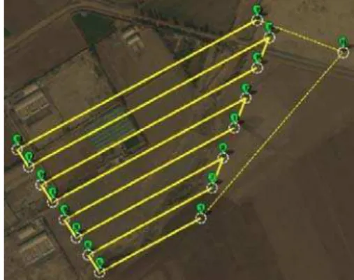
Figure 3. Flight Track (yellow line)
2.6 Data Processing
Processing of acquired images is done in 3 primary steps as following:
1- Structure from motion algorithm 2- Digital surface model generation 3- Ortho-mosaic generation
Structure from motion algorithm is used to reconstruct the 3D geometry scenes and camera orientation parameters from consequence of 2D images (Ullman, 1979; Fisher, 2005). To do this, SIFT algorithm (Lowe, 2004) is implemented to extract tie points throughout the sequence of multiple images. Using the extracted information as input in SFM algorithm, image projection center position, their relative orientations and estimated location of the tie points as sparse point clouds is the final output of this step. In contrast, camera calibration parameters are solved inside the algorithm.
In a second step, a dense, multiview-stereo reconstruction is applied on the oriented images for sparse points cloud densification (Seitz, 2006). This algorithm is based on pixel values.
Final step in this study is ortho-mosaic generation using meshed surface obtained by dense points clouds and imagery taken from UAV. There is no different between ortho-mosaic generation method from low altitude imagery obtained by UAV and traditional Arial photographs. However, there is some different in image acquisition step, in UAV due to use of non-metric camera and poor radiometric resolution, so it is necessary to set higher forward and side overlap between images.
3. EXPERIMENTAL RESULTS 3.1 Study Area
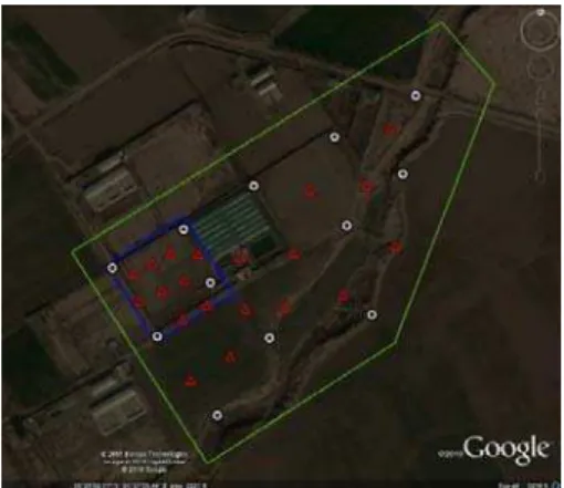
GPS via RTK technique. Figure 4 shows a sample of the signalize GCPs and Figure 5 illustrates the distribution scheme of GCPs and check points. The achieved accuracy for measured GCPs by dual-frequency GPS in horizontal is .5 and vertical accuracy is . .
Figure 4. A sample of the signalized ground control points.
Figure 5. Study area (green line), selected area for lever arm calibration (blue line), ground control points (white circle) and
check points (red triangle).
The flight was performed in February, 2016 at 10:00 – 11:00 local time over the area. During the flight for image acquisition, weather condition was good; the sky was sunny and clear; wind speed was approximately 7 m/s.
Camera preferences were defined shutter priority mode and the shutter speed was set to 1/1250s. The lens focus was set manually.
3.2 Results
First, lever arm calibration using the selected area (Figure 5) has done and its result was 25 cm with standard deviation of 5 cm. Then, the camera position is corrected via RTK data and attitude angles stored in flight mission log file.
Acquired images was processed two times, first indirect georeferencing with GCPs and next, by direct georeferencing method via corrected camera positions. Table 2 and 3 shows the accuracy of the methods compared to check points.
Points
Type No. XY Error (m) Z Error (m)
GCP 12
Mean 0.012 0.027
STD 0.005 0.008
RMSE 0.017 0.029
Check 20
Mean 0.041 0.052
STD 0.014 0.031
RMSE 0.053 0.068
Table 2. Summary of spatial error in indirect georeferencing
Type No. XY Error (m) Z Error (m)
Check 32
Mean 0.132 0.203
STD 0.034 0.053
RMSE 0.164 0.235
Table 3. Summary of spatial error in direct georeferencing
The summery of the indirect georeferencing accuracy on GCPs is shown in table 2, which is 1.2 cm in planimetric and 2.7 cm in vertical. On check point obtained accuracy was 4.1 cm in planimetric and 5.2 cm on vertical.
The summery of direct georeferencing accuracy with help of RTK module is shown in table 3, the evaluation is performed on 32 check points which are already measured and they have known position.
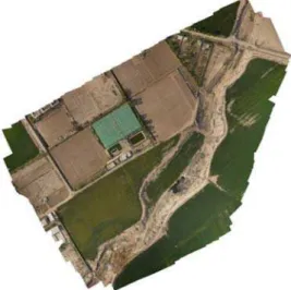
Figure 6 illustrate the sample of generated point clouds and figure 7 shows the generated ortho-mosaic of the whole area with GSD of 2.8 cm.
Figure 7. Ortho-mosaic
4. DISCUSSION
For evaluation of proposed system, we have already established 12 ground control points and 20 check points and they were measured by survey-grade dual frequency GNSS receiver in RTK mode. The generated point cloud is compared to these points to evaluate the potential of RTK UAV in automatic point cloud generation. It shows that decimeter accuracy level is achievable for the application of the 3D rapid mapping with proposed system. However, the obtained accuracy is affected by time synchronization delay and lever-arm calibration. As shown in table 1, selected flying speed parameter is restricted to 2 m/s, so this parameter is decrease the coverage. Beside, by increasing the flying speed, the accuracy of the final products will effect by time synchronization delay. Moreover, IR remote electronic hardware is used to control the camera that it limited the trigging interval of the camera to 3 second due to hardware restrictions.
5. CONCLUSION
The experimental results illustrate using of RTK systems on the UAV is fast and accurate than using of GCPs to register point cloud. Moreover, it can be concluded the RTK system for direct geo-referencing and eliminating the GCPs from point cloud and DSM generation process is sufficient and useful for rapid mapping systems. Moreover, the high resolution imagery collected from platforms have the capabilities to provide a quick overview of the disaster area with decimeter accuracy level as mentioned.
For obtaining better accuracy, some improvements and future works is required: solving hardware restriction of the camera trigging control to higher rate for increasing the speed of the flight; a method to reduce time delay and error of the sensors time synchronization to level of 0.1 millisecond for speed higher than 54 km/h to increase coverage area which is important in 3D rapid mapping applications.
REFERENCE
Aibotix, 2016. Aibot X6 Version 2 uses high precision GNSS. https://www.aibotix.com/en/press/articles/aibot-x6-v2-high-precision-gnss.html (12 Mar, 2016).
Ajmar, A., P. Boccardo, F. Disabato, and F. G. Tonolo, 2015. Rapid Mapping: geomatics role and research opportunities. Springerlink.com.
Daakir, M., M. P. Deseilligny, P. Bosser, F. Pichard and C. Thom, 2015. UAV Onboard photogrammetry and GPS positioning for earthworks. The International Archives of the Photogrammetry, Remote Sensing and Spatial Information Sciences,Vol. XL-3/W3, pp. 293-299.
Eling, C., L. Klingbeil, and H. Kuhlmann, 2014. A precise direct georeferencing system for UAVs. Proceedings of the Workshop on UAV-basaed Remote Sensing Methods for Monitoring Vegetation. 94, Koln, pp.33-41.
EVILRemote, 2011. http://swf.com.tw/en/open-source-sony-camera-ir-shutter-and-time-lapse-controller/ (12 Mar, 2016).
Fisher R., K. D. Howe, A. Fitzgibbon, C. Robertson and E. Trucco, 2005. Dictionary of Computer Vision and Image Processing. John Wiley & Sons: Hoboken.
Fritz, A., T. Kattenborn and B. Kocha, 2013. UAV-based photogrammetric point clouds – tree stem mapping in open stands in comparison to terrestrial laser scanner point clouds. The International Archives of the Photogrammetry, Remote Sensing and Spatial Information Sciences. Vol. XL-1/W2, pp. 141-146.
Gabrlik, P., 2015. The Use of Direct Georeferencing in Aerial Photogrammetry with Micro UAV. International Federation of Automatic Control (IFAC-PapersOnLine), 48(4), pp. 380–385.
Haala, N., M. Cramer and M. Rothermel, 2013. Quality of 3d point clouds from highly overlapping UAV imagery. The International Archives of the Photogrammetry, Remote Sensing and Spatial Information Sciences,Vol. XL-1/W2, pp. 183-188.
Harwin, S., and Arko Lucieer, 2012. Assessing the accuracy of georeferenced point clouds produced via multi-view stereopsis from unmanned aerial vehicle (UAV) imagery. Remote Sens., 4, pp. 1573-1599.
Lowe, D. G., 2004. Distinctive image features from scale-invariant keypoints. International journal of computer vision 60(2), pp. 91–110.
Mavinci, 2016. Sirius pro surveying UAS http://www.mavinci.de/en/siriuspro (12 Mar, 2016)
Maxtena, 2016. High performance active GPS antenna.
http://www.maxtena.com/m1575hct-15a-sma.html#.VuU2v_l95D8 (12 Mar, 2016)
Nebiker, S., A. Annena, M. Scherrerb, and D. Oeschc, 2008. A light-weight multispectral sensor for micro UAV: Opportunities for very high resolution airborne remote sensing. The International Archives of the Photogrammetry, Remote Sensing and Spatial Information Sciences., 37(1), pp. 1193–1198.
Sensfly, 2016. eBee the survey-grade mapping drone. https://www.sensefly.com/drones/ebee-rtk.html (12 Mar, 2016).
Seitz S., B. Curless, J. Diebel, D. Scharstein and R. Szeliski. 2006. A comparison and evaluation of multi-view stereo reconstruction algorithms. Proceedings of the CVPR ’06 IEEE Computer Society Conference on Computer Vision and Pattern
Recognition. Vol 1. IEEE Computer Society: Washington, DC,
pp. 519-526.
Shahbazi, M., G. Sohn, J. Théau, and P. Ménard, 2015. UAV-Based Point Cloud Generation for Open-Pit Mine Modelling. The International Archives of the Photogrammetry, Remote Sensing and Spatial Information Sciences., Vol. XL-1/W4, pp. 313-320.
Stempfhuber, W., and M. Buchholz, 2011. A precise, low cost RTK GNSS system for UAV applications. International Archives of the Photogrammetry, Remote Sensing and Spatial
Information Sciences, Zurich, Switzerland, Vol.
XXXVIII-1/C22, pp. 1-5.
Swift Navigation, 2016. https://www.swiftnav.com/piksi.html (12 Mar, 2016).
Takasu, T., and A. Yasuda, 2008. Evaluation of RTK-GPS performance with low-cost single-frequency GPS receivers. http://gpspp.sakura.ne.jp/paper2005/isgps2008_paper_ttaka.pdf (25 Mar. 2014).
Tampubolon, W., and W. Reinhardt, 2015. UAV data processing for rapid mapping activities. International Archives of the Photogrammetry, Remote Sensing and Spatial Information Sciences, Vol. XL-3-W3, pp. 371-378.
Tscharf, A., M. Rumpler, F. Fraundorfer, G. Mayer and H. Bischof, 2015. On the use of UAVs in mining and archaeology – geo-accurated 3d reconstructions using various platforms and terrestrial views. ISPRS Annals of the Photogrammetry, Remote Sensing and Spatial Information Sciences, Vol. II-1/W1, pp. 15-22.
Turner, D., A. Lucieer, and C. Watson, 2012. An automated technique for generating georectified mosaics from ultra-high resolution unmanned aerial vehicle (UAV) imagery, based on structure from motion (SfM) point clouds. Remote Sens., 4, pp. 1392-1410.
Turner, D., A. Lucieer, and L. Wallace, 2014. Direct georeferencing of ultrahigh-resolution UAV imagery. IEEE Trans. Geosci. Remote Sens., 52(5), pp. 2738-2745.
Ullman S., 1979. The interpretation of structure from motion. Proceedings of the Royal Society of London. B203, pp. 405–426.