Departamento de Informática e Matemática Aplicada Programa de Pós-Graduação em Sistemas e
Computação
Formal verification of PLC programs using
the B Method
Haniel Moreira Barbosa
Formal verification of PLC programs using the B Method
Dissertação apresentada ao Programa de Pós-Graduação em Sistemas e Computação do Departamento de Informática e Matemá-tica Aplicada do Centro de Ciências Exatas e da Terra da Universidade Federal do Rio Grande do Norte como requisito parcial para a obtenção do grau de Mestre em Sistemas e Computação.
Orientador
Prof. Dr. David Déharbe
Universidade Federal do Rio Grande do Norte — UFRN Programa de Pós-Graduação em Sistemas e Computação — PPgSC
tada por Haniel Moreira Barbosa e aceito pelo Programa de Pós-Graduação em Sistemas e Computação do Departamento de Informática e Matemática Aplicada do Centro de Ciên-cias Exatas e da Terra da Universidade Federal do Rio Grande do Norte, sendo aprovado por todos os membros da banca examinadora abaixo especificada:
Prof. Dr. David Déharbe Orientador
Departamento de Informática e Matemática Aplicada Universidade Federal do Rio Grande Norte
Prof. Dr. Marcel de Oliveira
Departamento de Informática e Matemática Aplicada Universidade Federal do Rio Grande do Norte
Prof. Dr. Alexandre Mota
Centro de Informática Universidade Federal de Pernambuco
Agradeço aos meus pais, que tanto me apoiaram, que tanto me elevaram... e que por tanto tempo não tiveram o reconhecimento devido.
Aos meus professores, que tanto me ensinaram, positiva ou negativamente.
A David, que me aguentou. A Thierry, que me deu uma oportunidade que tentei aproveitar ao máximo.
Aos meus amigos, pela força, pelos puxões de orelha, pelo necessário escapismo, pela esperança.
people do not believe they can learn, and how many more believe learning to be difficult. Muad’Dib knew that every experience carries its lesson.
List of Figures
List of Tables
List of Codes
Resumo
Abstract
1 Introduction p. 20
1.1 Goals . . . p. 23
1.2 Structure of the dissertation . . . p. 23
2 Related work p. 24
2.1 Approaches using theorem proving . . . p. 25
2.2 Approaches using model checking . . . p. 27
2.3 Approaches using simulation . . . p. 29
2.4 Considerations . . . p. 30
3 Context and techniques p. 33
3.1 Programmable Logic Controllers . . . p. 33
3.1.1 IEC 61131 . . . p. 34
3.1.2 PLC programming . . . p. 36
3.1.2.3 IL . . . p. 38
3.1.2.4 ST . . . p. 40
3.1.2.5 Graphical languages . . . p. 40
3.1.2.6 FBD . . . p. 42
3.1.2.7 LD . . . p. 43
3.1.2.8 SFC . . . p. 45
3.2 PLCopen . . . p. 51
3.2.1 Variables and Data types . . . p. 51
3.2.1.1 Data Type . . . p. 52
3.2.1.2 Value . . . p. 54
3.2.2 POUs . . . p. 55
3.2.2.1 Interface . . . p. 56
3.2.2.2 Body . . . p. 56
3.2.3 Additional Data . . . p. 62
3.3 B Method . . . p. 62
3.3.1 AMN notation . . . p. 63
3.3.2 Substitutions . . . p. 67
3.3.3 Proof Obligations . . . p. 69
3.3.4 Example . . . p. 71
3.3.5 Decomposition . . . p. 73
3.3.6 Tools . . . p. 77
4 Method p. 79
4.1 Reading the PLC programs . . . p. 81
4.1.1 PLC Object . . . p. 81
4.1.2.2 PLC Example . . . p. 88
4.1.3 PLCopen Reader . . . p. 93
4.2 Generating the B Model . . . p. 94
4.2.1 Architecture of the B model . . . p. 94
4.2.2 Translation Process . . . p. 96
4.2.2.1 ST . . . p. 96
4.2.2.2 FBD . . . p. 103
4.2.2.3 LD . . . p. 106
4.2.2.4 SFC . . . p. 109
4.2.3 B Writer . . . p. 112
4.2.3.1 Static information and structuring . . . p. 113
4.2.3.2 State . . . p. 115
4.2.3.3 Behaviour . . . p. 119
4.3 Inserting the safety constraints . . . p. 132
4.3.1 Example . . . p. 133
4.4 Restrictions of the approach . . . p. 134
5 Case Study p. 137
5.1 Application description . . . p. 137
5.1.1 Doors subsystem . . . p. 138
5.1.2 Central Door Controller . . . p. 139
5.1.2.1 PLC program for CDC . . . p. 141
5.2 Applying the method . . . p. 144
5.2.1 B model . . . p. 144
5.2.2 Safety constraints . . . p. 148
5.3.2 Model checking . . . p. 153
5.4 Conclusions . . . p. 154
6 Conclusion p. 156
References p. 160
Appendix A -- Textual languages constructs p. 163 A.1 IL Constructs . . . p. 163
A.2 ST constructs . . . p. 164
Appendix B -- Textual declarations in IEC 61131-3 p. 165 B.1 POU declaration . . . p. 165
B.2 SFC declaration . . . p. 167
Appendix C -- CDC extra information p. 168
C.1 Class diagramas to the PLC Object . . . p. 168
Appendix D -- CDC extra information p. 171
D.1 CDC interface . . . p. 171
D.2 Doors system elements . . . p. 172
Chapter 2: Related work p. 24
1 Verification techniques . . . p. 31
2 Approach’s automation . . . p. 31
Chapter 3: Context and techniques p. 33
3 A PLC system. . . p. 35
4 The five languages of the IEC 61131-3 standard for PLC programming. p. 36
5 Block corresponding to the IL function seen in Section 3.1.2.3. . . p. 42
6 Block corresponding to the ST function seen in Section 3.1.2.4. . . p. 42
7 FBD program example . . . p. 43
8 Example of a program in the LD language. . . p. 45
9 LD diagram making use of FBD elements. . . p. 45
10 A sequence of SFC steps connected by transitions. . . p. 47
11 Valid step’s connections. . . p. 47
12 Valid transition’s connections. . . p. 47
13 SFC program with selection structures. . . p. 48
14 SFC program with simultaneous structures. . . p. 49
15 A SFC program wrongly using the simultaneous convergence element. . p. 49
16 SFC program presenting the discussed elements . . . p. 50
17 Architecture of a B model with decomposition . . . p. 76
19 Framework we built to implement our method. . . p. 80
20 The main elements of Types . . . p. 82
21 Types object built. . . p. 91
22 POU object built. . . p. 91
23 Interface of the POU sfcSimple. . . . p. 91
24 DataTypeElements built. . . p. 92
25 Body of “sfcSimple”. . . p. 92
26 BodyLD and BodyLD . . . p. 93
27 Architecture of the B model generated. . . p. 94
28 FBD program to be translated to B notation . . . p. 106
29 LD program to be translated to B notation . . . p. 108
30 SFC example modified. . . p. 110
31 Action2, in LD . . . p. 110
32 B translation for SR function block . . . p. 134
Chapter 5: Case Study p. 137
33 Overall structure of a train’s door subsystem. . . p. 138
34 Central Door Controller, system view. . . p. 140
35 Central Door Controller, SFC program. . . p. 141
36 POU functions used by the CDC. . . p. 142
37 POU function blocks used by the CDC. . . p. 142
38 B model for the CDC. . . p. 145
Chapter C: CDC extra information p. 168
39 PLC Object — Class diagram . . . p. 168
42 LDObjects — Class diagram . . . p. 170
43 FBDObjects — Class diagram . . . p. 170
Chapter D: CDC extra information p. 171
44 Doors system — Class diagram . . . p. 172
45 Doors system — Class diagram . . . p. 173
46 Doors system — Class diagram . . . p. 173
47 Doors system — Class diagram . . . p. 173
48 Doors system — Class diagram . . . p. 173
49 Doors system — Class diagram . . . p. 174
50 B model for the instance of the Define_ButtonEmergency function block. p. 175
Chapter 2: Related work p. 24
1 List of related works . . . p. 31
Chapter 3: Context and techniques p. 33
2 Elementary types. . . p. 38
3 I/O Table for IL example. . . p. 39
4 I/O Table for ST example. . . p. 40
5 Common elements to IEC 61131 graphical languages . . . p. 41
6 Graphical elements of the FBD language . . . p. 44
7 Graphical elements of the LD language . . . p. 44
8 Graphical elements of the SFC language . . . p. 46
9 I/O Table for SFC example. . . p. 50
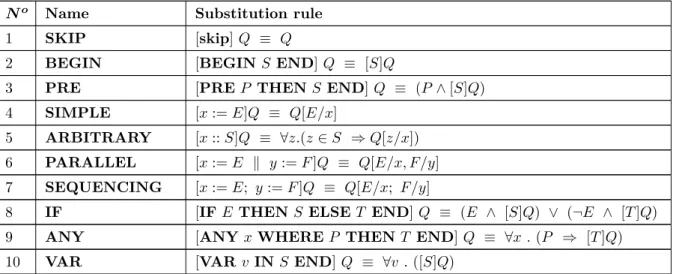
10 Rules of Substitution in B . . . p. 67
Chapter 4: Method p. 79
11 ST operations and their equivalent B notations . . . p. 97
Chapter 5: Case Study p. 137
12 Invariants inserted into the B model for CDC. . . p. 150
13 Proof obligations generated to verify the B model for CDC. . . p. 151
Chapter A: Textual languages constructs p. 163
16 Elements of the instructions in IL. . . p. 163
17 ST operations and their symbols . . . p. 164
18 ST statements and examples of their usage. . . p. 164
Chapter D: CDC extra information p. 171
19 CDC — Interface . . . p. 171
20 Interface of Test_Opening . . . p. 171
21 Interface of Test_Closing . . . p. 171
22 Interface of Define_MechEmergency . . . p. 172
Chapter 3: Context and techniques p. 33
1 Example of a IL program. . . p. 39
2 Example of a ST program. . . p. 41
3 Action1, in ST . . . p. 50
4 XML element to a Variable . . . p. 52
5 XML representation of a boolean variable . . . p. 52
6 XML representation of a new type based on the Enumeration data type. p. 53
7 XML element for the Array Type . . . p. 54
8 XML representation of an array variable . . . p. 54
9 XML representation of an array variable with an initial value associated. p. 55
10 Interface of a POU in PLCopen. . . p. 56
11 Block in PLCopen . . . p. 58
12 SFC POU in PLCopen — Interface , Actions and Transitions . . . p. 60
13 SFC POU in PLCopen — Body . . . p. 61
14 Example of use of the Add Data feature . . . p. 62
15 Basic structure of a B machine . . . p. 63
16 Basic structure of a B refinement . . . p. 65
17 Example of a B machine. . . . p. 71
18 Necessary alteration for invariant compliance . . . p. 71
19 Example of a B refinement . . . p. 73
Chapter 4: Method p. 79
22 Algorithm for the PLC reading . . . p. 83
23 Algorithm for the PLC reading . . . p. 85
24 Algorithm for the SFC Body construction . . . p. 86
25 Algorithm for the Action parsing . . . p. 87
26 Algorithm for the Transition parsing . . . p. 88
27 Textual representation of some Data Type Elements declaration. . . p. 89
28 Textual representation of a POU function in ST declaration . . . p. 89
29 Textual representation of a POU program implemented with SFC + ST. p. 89
30 B generation from ST function block invocation . . . p. 98
31 B generation from ST function invocation . . . p. 99
32 B generation from ST function block invocation . . . p. 100
34 B generation from ST assignments . . . p. 102
35 B generation from ST ’IF’ statements . . . p. 103
36 B generation from ST example . . . p. 103
38 B generation from FBDTest example . . . p. 106
40 B generation from LD example . . . p. 108
41 B generation from a SFC body . . . p. 109
42 B generation from LD example . . . p. 110
43 B precondition generation from Step connections . . . p. 111
44 Guidelines for generating POU functions translations. . . p. 122
45 B generation from ST code in a POU function . . . p. 122
46 Abstract operation from FBD1 body . . . p. 124
49 Abstract simultaneous divergence operation from SFC body. . . p. 127
50 Refinement operation from FBD1 body. . . p. 128
51 Refinement operations from LD body . . . p. 129
52 Refinement step operations from SFC body . . . p. 131
53 Refinement simultaneous divergence operation from SFC body . . . p. 132
Chapter 5: Case Study p. 137
54 Action Evaluate Closing, at Step3 . . . p. 142
55 POU function Test Closing’s ST body. . . p. 142
56 Action Evaluate Emergency, at Step8 . . . p. 143
57 Function block Define_MechEmergency. . . p. 144
58 B operation for Step8 . . . p. 146
59 B operation for POU function Test Closing . . . p. 147
60 B operation for POU function block instance test_MEmg . . . p. 147
Chapter B: Textual declarations in IEC 61131-3 p. 165
61 Production rules for the textual declaration of a PLC program . . . p. 165
62 Production rules for the textual declaration of a POU function . . . p. 165
63 Production rules for the textual declaration of a POU function block . . p. 166
64 Production rules for the textual declaration of a POU program . . . p. 166
Method
Autor: Haniel Barbosa Orientador: Prof. Dr. David Déharbe
Resumo
Controladores Lógico Programáveis (PLCs —Programmable Logic Controllers, em inglês) desempenham funções de controle, recebendo informações do ambiente, processando-as e modificando este ambiente de acordo com os resultados obtidos. São comumente utilizados na indústria nas mais diversas aplicações, do transporte de massa à indústria do petróleo, gás e energias renováveis. Com o crescente aumento da complexidade dessas aplicações e do seu uso em sistemas críticos, faz-se necessária uma forma de verificação que propicie mais confiança do que testes e simulação, padrões mais utilizados na indústria, mas que podem deixar falhas não tratadas. Métodos formais podem prover maior segurança a este tipo de sistema, uma vez que permitem a sua verificação matemática. Neste trabalho fazemos uso do Método B, que é usado com sucesso na indústria para a verificação de sistemas críticos, possui amplo apoio ferramental e suporte à decomposição, refinamento e verificação de corretude em relação à especificação através de obrigações de prova. O método desenvolvido e apresentado aqui consiste em gerar automaticamente modelos B a partir de programas para PLCs e verificá-los formalmente em relação a propriedades de segurança, estas derivadas manualmente a partir dos requisitos do sistema. O escopo do trabalho são as linguagens de programação para PLCs do padrão IEC 61131-3, mas sistemas com linguagens que apresentem modificações em relação ao padrão também são suportados. Esta abordagem visa facilitar a integração de métodos formais na indústria através da diminuição do esforço para realizar a verificação formal de PLCs.
Method
Author: Haniel Moreira Barbosa Advisor: Prof. Dr. David Déharbe
Abstract
PLCs (acronym for Programmable Logic Controllers) perform control operations, re-ceiving information from the environment, processing it and modifying this same environ-ment according to the results produced. They are commonly used in industry in several applications, from mass transport to petroleum industry. As the complexity of these ap-plications increase, and as various are safety critical, a necessity for ensuring that they are reliable arouses. Testing and simulation are the de-facto methods used in the indus-try to do so, but they can leave flaws undiscovered. Formal methods can provide more confidence in an application’s safety, once they permit their mathematical verification. We make use of the B Method, which has been successfully applied in the formal verifi-cation of industrial systems, is supported by several tools and can handle decomposition, refinement, and verification of correctness according to the specification. The method we developed and present in this work automatically generates B models from PLC programs and verify them in terms of safety constraints, manually derived from the system requi-rements. The scope of our method is the PLC programming languages presented in the IEC 61131-3 standard, although we are also able to verify programs not fully compliant with the standard. Our approach aims to ease the integration of formal methods in the industry through the abbreviation of the effort to perform formal verification in PLCs.
1
Introduction
Programmable Logic Controllers (from now on, PLCs) perform control operations in a system, running inexecution cycles: they receive information from the environment as inputs, process them and affect this environment with the resulting outputs, controlling some aspects of it. This work deals with discrete-time PLCs, which receive and process signals with fixed values, so they are always defined given a particular time instant, in opposite to a continuous-time signal, a function defined at every time in an interval.
In many fields, such as mass transport and petroleum industry, it is very common to use PLCs to handle control applications. Those are mostly programmed according to IEC 61131-3 (IEC, 2003), an international standard that specifies the five standard PLC programming languages, namely: LD (Ladder Diagram) and FBD (Function Block Dia-gram) as graphical languages; IL (Instruction List) and ST (Structured Text) as textual languages; and SFC (Sequential Function Chart), that shows the structure and internal organization of a PLC. It is not rare that a variation of such languages is employed too.
As the complexity of the PLC applications increases, and as various are critical, it is important to ensure their safety (KRON, 2003). Since testing and simulation, the de-facto methods in many industries to perform verification, can leave flaws undiscovered, which may be intolerable given the level of risk acceptance of a system, another strategy is necessary. A mean to fulfill this requirement is with formal methods, mathematical approaches to software and system development which support the rigorous specification, design and verification of computer systems (FME, 2012). However, they are difficult to integrate with the industrial process (AMEY, 2004), since most control engineers are not familiarized with formal verification (PARNAS, 2010).
Another positive point is the B language itself, which is very expressive, including first order logic, integers and set theory, and on top of that it can handle decomposition, refine-ment, verification of correctness according to the specification and generation of certified code (LECOMTE et al., 2007). Nonetheless, the difference in expressivity between B and the PLC languages, like the lack of float numbers in the former, lead to restrictions on how much of the PLC programs we can cover.
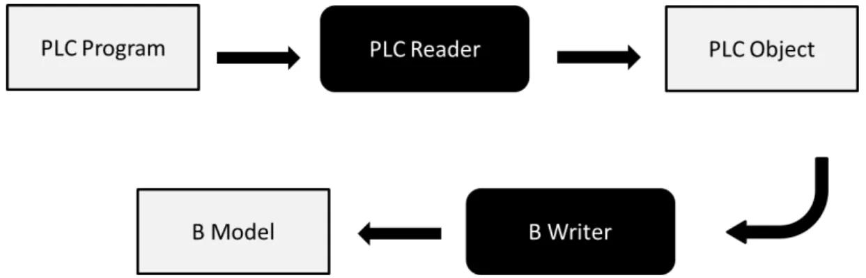
Our approach consists of developing a tool that receives a PLC program based on the IEC 61131-3 standard and automatically builds an intermediary object from it. From this object a formal model in the B notation is generated, also automatically. The cor-rectness of this translation, between the PLC program and the B model representing it, is not mathematically verified, its confidence relying on expertise and simulations over the model’s behaviour. Safety constraints are then manually inserted into the B model and verified using theorem proving, which allows us to cover the full behavior set of the problem in unlimited depth. We can verify structural properties, such asdeadlock freedom, performing model checking in the model, although some adaptations may be necessary in the model, like restricting its state space, due to the different nature of the verifica-tion techniques. We use the ProB (LEUSCHEL and BUTLER, 2003) Model Checker to analyze the model, which also supports the definition and verification of new properties using Linear Temporal Logic (BLACKBURN et al., 2001), such asliveness; animation of the model is available as well, providing visual validation. Our approach is thus able to verify that the PLC is presenting the expected behaviour in itsexecution cycle.
Automation is a key aspect of our work since it is essential for the success of a verification technique to be used by engineers, in our case PLC developers, that it insures viability, allowing the formalism to be mostly hidden from them. Although the safety constraints have to be manually inserted in the model, given that they were already available one would have only to run the tool implementing the method over the PLC programs to perform formal verification on them, allowing error management. In order to keep the formalism hidden from them also during the error management phase the results of the verification should be presented in a readable way for the engineers, but that is still between the limitations of our approach.
Object stands between the PLC programs and the formal models to be generated, hence reducing the semantic gap between PLCs and B, and defining a unique representation for different PLC languages (FARINES et al., 2011). The process also involves the develop-ment of a customizable parser, so we can treat PLC programs that do notstrictly follow the IEC standard; as numerous legacy systems deviate from the standard, our approach would thus be able to handle them.
Being able to deal with legacy systems is a very useful feature once there are nu-merous existing PLC programs not amenable to be formally treated except with formal methods (FREY and LITZ, 2000). Reverse engineering can be performed in these pro-grams so a PLCopen documentation can be generated, a desirable feature as well, as an equivalent program, easier to understand and maintain, is acquired.
We also present a case study in a real safety-critical railway system: the Central Door Controller (from now on, CDC), part of the doors subsystem of a train. We show the step by step automatic generation of the formal specification from its PLC program and, after defining the safety constraints, perform a full formal verification in the application, at the end exhibiting the results.
Thus, the main contributions in our work are:
1. The automatic generation of formal models from PLC programs, facilitating the insertion of formal methods in the industrial process.
2. To have correctness, according to the specification, as a realistic and achievable goal in PLC development, with the verification of safety constraints by theorem proving.
3. Allowing the structural and behavioral verification of the PLC programs through model checking, LTL checking and animation over the formal model.
4. Evaluation of the proposed approach in a case study.
the covered elements of the PLC languages due to restrictions of the B language. A full account of the limitations of our approach may be found in Chapter 4, at Section 4.4.
1.1
Goals
In a nutshell, our goals in this work are:
1. Automatically build an intermediary structure instance representing the information in the PLC programs.
2. Reduce the semantic gap between the PLC programs and the formal models through an intermediary structure.
3. Provide documentation to PLC programs using PLCopen.
4. Automatically generate B models from the intermediary structure.
5. Insert safety constraints, extracted from the requirements of the PLC system, in the B models generated.
6. Perform formal verification through theorem proving and model checking over the B models generated.
7. Evaluate the method developed to accomplish the previous goals through a case study in a real industrial setting.
1.2
Structure of the dissertation
2
Related work
As stated in (FREY and LITZ, 2000), there are several reasons for the application of formal methods in PLC programming:
• “The growing complexity of the control problems, the demand for reduced
develop-ment time1, and the possible reuse of existing software modules result in the need for a formal approach in PLC programming.”
• “The demand for high quality solutions and especially the application of PLC in safety-critical process need verification and validation procedures, i.e. formal methods to prove specific static and dynamic properties of the programs, as for example liveness, unambiguity or response times.”
In this chapter we present some works that have been trying to tackle these issues, categorizing them, as in (FREY and LITZ, 2000), based on the method applied to do so:
• Model checking: “It is an automatic technique for verifying finite-state reactive
systems, such as sequential circuit designs and communication protocols. Specifi-cations are expressed in temporal logic, and the reactive system is modeled as a state-transition graph. An efficient search procedure is used to determine whether or not the state-transition graph satisfies the specifications” (CLARKE et al., 1999). While testing and simulation explore only some of the possible behaviours of sys-tems, model checking makes an exhaustive exploration of all possible behaviours, checking the validity of a given property and providing counter examples when the system does not satisfy it. This exhaustive search, however, leads to one of the main disadvantages of model checking, the state-explosion problem — since the number os states grows exponentially in the number of system’s variables, the procedure
1
may be prevented from terminating timely. Then it is usually limited to some bound, in order to avoid this issue, reducing its coverage.
• Theorem Proving: It proves that an implementation satisfies a specification by
mathematical reasoning, without the need of searching all possible states in a model, as expected properties are formalized using some mathematical logic. A Theorem Prover assists the user in formulating the proof. One of its greatest advantages is the avoidance of the state-explosion problem, as this approach allows one to deal with the full behavior set of a problem in unlimited depth. Between its disadvantages are the considerable technical expertise and understanding of the system required, as well as the fact that if the proof of a property fails, the prover will not tell whether the property is indeed unprovable or whether it is lacking information to complete the proof, relying on the user the task of verifying what is the scenario.
After presenting the approaches to formal verification we show some semi-formal ap-proaches, tackling the verification effort withsimulation techniques, where the validation is made against an informal specification. Its problem is that it is never complete and it takes considerable time and efforts (FREY and LITZ, 2000).
These works deal with PLC programs according to the IEC 61131-3 standard, but most are focused only in a subset of the standard five languages (SFC, LD, FBD, ST, IL): to the best of our knowledge, only one related work, on formal verification, considers the whole standard, and it also uses PLCopen, like our proposed approach.
2.1
Approaches using theorem proving
(SÜFLOW and DRECHSLER, 2008)
The approach presented in (SÜFLOW and DRECHSLER, 2008) proposes the auto-matic translation of an IL program into a SystemC model, so a high level representation of the former is obtained, which is then compared, through Equivalence Checking using SAT solvers, with a reference model specification, showing that they are functionally equivalent.
into several modules. Through a series of rules a transformation takes place from IL programs to a semantic equivalentSystemC model, which can then be formally verified.
SAT solvers evaluate a given boolean formula and determine if it is satisfiable2. In this approach it is used to perform equivalence checking between the SystemC resulting translation of the IL program and a given reference specification.
The variables, basic statements and control flow statements of IL are covered by this approach, as well as call statements. It is a wide-ranging one in terms of IL. Nonetheless, asproperties checking is not performed, only the validation of the translation process with a reference model — which has to be manually constructed —, the contribution of the work has still to be increased.
(CAVALCANTI et al., 2011)
A strategy to translate Simulink diagrams into Circus and to prove that a parallel ADA implementation refines this Circus specification is presented in (CAVALCANTI et al., 2011). Simulink is a block-based language for control appli-cations, similar to FBD (Function Block Diagram); although it is not used in PLCs their principals are much alike. Circus is a notation that combines Z, CSP, and a refinement calculus, thus capable of formal modeling and analyzing the data structures (Z) and com-munication and concurrency features (CSP) of a system.
The approach consists of validating and extending existing industrial tools that trans-late discrete-time Simulink diagrams into Ada implementations. This is done by proving the correctness of the translation by verifying that a Circus model for the Simulink di-agram is refined by another Circus model for the generated Ada implementation. The approach makes use of the ClawZ tool, that generates bits of Z and CSP models from Simulink diagrams and, by a series of refinements, obtain aCircus model capable of being verified by the theorem prover ProofPower, proving whether this model refines the one for its respective Simulink diagram.
Time-related issues are not covered in this work, but parallelism is easily handled by CSP, as well as other features such as the dependency between the order in which the inputs are received by a block and its resulting outputs. Simulink has a library of standard blocks to whom a corresponding library of translated specifications is available inClawZ.
2“f is valid” — always true, a theorem —
A setback in the work is the lack of automation, but the authors state they are going to carry this out as future work — the steps of the approach have already been proven correct and are automatable. Efforts to produce a toolset are being made, so a powerful resource in the analysis of control diagrams and their implementations can be obtained, aiming error management as well.
(VÖLKER and KRÄMER, 1999)
In (VÖLKER and KRÄMER, 1999) the proposed approach deals with PLC function blocks implemented using FBD, SFC or ST. It aims to prove the correctness of the compo-nents independently, so the applications who use them may have their verification process considerably simplified, since only the component’s integration has to be checked.
Higher order logic (HOL) is used for verification purposes. It provides abstraction and quantification, which makes it a very expressive mechanism, suited for the description of complex theories. HOL serves as a logical glue that connects different programming and specification formalisms and allows their integration and analysis within the framework. The Isabelle tool3 is used for theorem proving automation.
The process described in the paper embodies a subset of the ST language in HOL, thus representing its syntax and semantics. Subsets of SFC and FBD are interpreted in terms of ST and therefore also taken into account. Requirements derived from the controller specification are inserted into the model in Linear Temporal Logic.
Results claim that small examples are easily handled by the verification toolchain, however larger specifications need alterations in the translation tactics for the generation of the HOL theories, so the verification can be eased. How much of the SFC, FBD and ST languages are present in the subsets covered by the approach is not specified, neither how much of the process of the HOL theories derivation is automatic.
2.2
Approaches using model checking
(RAUSCH and KROGH, 1998)
The approach presented in (RAUSCH and KROGH, 1998) aims to perform formal
3
verification over PLC programs by converting them to SMV, state transition systems, once the latter allows the engineer to verify the behavior of the control program over all possible operating conditions.
SMV is a language used to describe Mealy automata, synchronous or asynchronous networks and deterministic or non-deterministic process. As it provides modular descrip-tions it is suitable to retain the structure of the original control program, thus keeping traceability between the formal verification and the original PLC program. The verifica-tion of the SMV modules is made through model checking over its Computaverifica-tional Tree Logic (CTL) (BLACKBURN et al., 2001) specification, evaluating if this CTL specifica-tion is true and providing a counter-example otherwise.
Each state transition in the SMV model corresponds to one scan of the PLC program, so the transient behavior of the PLC during its execution is represented in the model. The language in the scope of this approach was only LD. Although the process is efficient to perform formal verification of PLC programs it is not automatic, despiste the fact that integration with other tools was also intended.
(SOLIMAN and FREY, 2009)
In (SOLIMAN and FREY, 2009) a method is proposed to verify applications using Safety Function Blocks with timed-automata through model-checking and simulation.
Safety Function Blocks (SFBs) are a special kind of function block whose presentation is divided in three parts: firstly, a graphical description of its internal state and behavior; then a list of its properties in natural language, that, with the other part being composed of timing diagrams describing its temporal behavior, for some specific scenarios, may be used to verify its safety.
All the twenty SFBs defined by PLCopen were successfully formalized following this approach. The challenge faced by the method was with networks, several SFBs inter-connected, assuring that the overall system would be compliant to the safety conditions as well as the independent components. The approach presented is useful, however the automation is still in their future works, and the scope is limited only to the SFBs.
(FARINES et al., 2011)
A model-driven engineering approach is used in (FARINES et al., 2011) to generate models in a FIACRE (Intermediate Format for the Embedded Distributed Component Architectures) language from LD programs. The work makes use of an intermediary model to reduce the semantic gap between the LD programs and the Timed Transition System (TTS) models that are verified through the toolkit TINA (TImed petri Net Analyzer); it is inserted in the context of the TOPCASED project4, which aims the development of an environment for embedded systems, based on Model-Driven Engineering (MDE).
The accuracy of the model transformation in the approach is grounded on the use of metamodel hierarchy in the representation of Domain Specific Modeling Languages. The FIACRE intermediary model is generated from the LD programs in the XML format of PLCopen. Then, a Frac compiler, of the TOPCASED project, is used to generate the TTS model for verification. LTL formulas, written by the PLC program designer, will be used to represent the system properties to be validated through model checking.
The strength of the approach is in the use of the FIACRE intermediary language to model the PLC, as a PLC model is automatically generated from the LD programs and FIACRE eases the inclusion of verification tools such as TTS. Extension to the other languages of IEC 61131-3 standard is intended for this project.
2.3
Approaches using simulation
(PARK et al., 2008)
In (PARK et al., 2008) an approach to perform visual verification of PLC programs through the modeling of a 3D plant where they run is performed. Not only the control
4
software is analyzed, but the whole system where it is inserted, with the environment being taken into account, a very interest feature that helps the validation of PLCs.
A PLC programming environment is presented along with a methodology for the construction of a plant model based on the DEVS (Discrete Event Systems Specification) formalism. This plant model is used for visual validation of PLC programs through si-mulation, taking into account also how the program interacts with its environment and if the actuation performed in it is as expected. The use of the DEVS formalism in the modeling of an environment adaptable to different configurations allows the generation of state transition systems representing the different tasks executable in the plant, which are also considered when simulating the PLC programs.
(WANG et al., 2012)
The application of a technique to validation of PLCs through simulation is described in (WANG et al., 2012) through a case study in a PLC-controlled system. The Behavior-Interaction-Priority (BIP) component framework is used to model a gate control system in a real industry application, also taking into account real-time constraints and the system with whom the control software interacts, making the validation through simulation.
The requirements of the system where modeled as monitors that during system com-ponent’s simulation checked if any transition to a not allowed behaviour occurred. Each property was checked independently through random and controlled set behaviours for the system model, eventually finding erros that helped the correction of the original PLC application.
Major setback, as well as in the previous approach, is the dependency of confidence in the modeling and simulation processes, as only visual validation is performed in the system. Nonetheless the decomposition support is of great help for mastering complexity; the ability to deal with time constraints and the approach’s overall expressivity also contribute to make it a powerful resource.
2.4
Considerations
sup-port through B mechanisms, helping us to master complexity, as in (WANG et al., 2012); the construction of a verification environment based on theorem proving but that supports other techniques, like model checking, as intended by (VÖLKER and KRÄMER, 1999) and its HOL use; visual validation through animation provides simular results as the si-mulation approaches in (WANG et al., 2012) and (PARK et al., 2008), although without the expressivity claimed by them.
Our approach begins intended to tackle the verification of PLC programs in all the languages of the standard, through PLCopen, something intended only by (FARINES et al., 2011). We also automatically generate the formal models to be veri-fied, something only a few of the presented approaches make, to the best of our knowledge.
Number Related work
[1] Our work
[2] (SÜFLOW and DRECHSLER, 2008)
[3] (VÖLKER and KRÄMER, 1999)
[4] (RAUSCH and KROGH, 1998)
[5] (SOLIMAN and FREY, 2009)
[6] (FARINES et al., 2011)
[7] (CAVALCANTI et al., 2011)
[8] (WANG et al., 2012)
[9] (PARK et al., 2008)
Table 1: List of related works
In Table 1 a list with the covered related works is presented, with Venn Diagrams below, in Figures 1 and 2, relating the verification techniques and the level of automation of them with our work, whose reach is depicted in light gray.
[2, 3] [7] [1]
Theorem Proving [8, 9] Simulation
[4, 6] [5]
Model Checking
Figure 1: Verification techniques
[4,5,8,9] [1, 6]
Manual
Automatic
[3, 7]
Semi-automatic
Figure 2: Approach’s automation
3
Context and techniques
In this chapter we present the basic concepts of Programmable Logic Controllers (PLCs), of the PLCopen standard and of the B Method, the basic elements of our work.
For the PLCs we introduce how they are organized and programmed, according to the international standards. We present the PLCopen standard in detail, with its XML based format. For the B method we make a whole presentation of its notation and features.
3.1
Programmable Logic Controllers
Programmable Logic Controllers are digitally operating electronic systems designed for use in an industrial environment. They use a programmable memory for the internal storage of user-oriented instructions in order to implement specific functions such as logic, sequencing, timing, counting and arithmetic, to control, through digital or analogue inputs and outputs, various types of machines or processes. Both the PLC and its associated peripherals are designed so that they can be easily integrated into an industrial control system and easily used in all their intended functions (IEC, 2003).
PLCs have become very common in control applications throughout the industry, from the mass transport field to the beverage factories. Being applied in many different fields and situations, however, led to the existence of several differences in the way they were constructed, as in I/O addressing, memory organization and instruction sets, for ins-tance. Aiming a standardization, the IEC (International Electrotechnical Commission), a worldwide organization for standardization comprising all national electrotechnical com-mittees, defined the 61131 standard, which establishes the definitions and identifies the main characteristics relevant to the selection and application of programmable logic con-trollers and their associated peripherals (IEC, 2003).
standard for PLC programming.
3.1.1
IEC 61131
The IEC 61131 embodies a series of standards over PLCs, from their general infor-mation and equipment requirements to their programming and use, as seen below:
1. General information
2. Equipment requirements and tests
3. Programming languages
4. User guidelines
5. Communications
6. Reserved
7. Fuzzy-control programming
8. Guidelines for the application and implementation of programming languages for programmable controllers
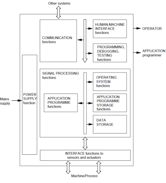
In this section we present in detail the standards IEC 1 and IEC 61131-3 (IEC, 20061131-3), which present the general information and the programming languages for PLCs, respectively. The general structure of a PLC, as an embedded system, is depic-ted in Figure 3.
The main part is the one responsible for signal processing, the CPU of the PLC. It consists of the application program storage, the data storage, the operating system, and the execution of the application program functions. The CPU function processes signals obtained from sensors as well as internal data storage and generates signals to actuators as well as internal data storage in accordance with the application program.
Figure 3: A PLC system.
inputs and outputs is temporarily stored and updated until the end of execution of the application program, as well as data required by it.
A PLC program is generally executed repeatedly as long as the controlled system is running. An application program may consist of a number of tasks, while the execution of each task is accomplished sequentially, one programmable function at a time until the end of the task. The initiation of a task, periodically or upon the detection of an event (interrupt condition), is under the control of the operating system.
The communication function provides data exchange with other systems, such as other PLCs, computers, etc. Thehuman-machine interface (HMI) makes the interaction between the operator, the signal processing function and the machine/process. The pro-gramming, debugging, testing and documentation functions are responsible for supplying auxiliary features to the PLC; theprogramming functionality is specially important to us, since it is the one used to build thekey element of the CPU: the application program, a logical assembly of all the programming language elements and constructs necessary for the intended signal processing required by a PLC. The programming languages defined in the IEC 61131-3 standard are presented in the next section.
3.1.2
PLC programming
The Part 3 of the IEC 61131 standard, IEC 61131-3, defines five languages for PLC programming, which are classified as shown in Figure 4. ST and IL are textual languages, while FBD and LD are graphical languages. SFC, besides its own elements, can be used in conjunction with any of the textual and graphical languages. They are described in detail below, with the languages’ elements summarized, examples presented and applications hinted.
Figure 4: The five languages of the IEC 61131-3 standard for PLC programming.
3.1.2.1 Program Organization Units
The PLC programs are composed of POUs — Program Organization Units. These elements are implemented using the languages of the standard and are divided in three categories:
i.e., invocation of a function with the same arguments shall always produce the same result.
• The POU function blocks produce one or more values as result. The state of a function block persists from one execution to the next — they are stateful — , therefore invocation with the same arguments may produce different results.
• The POU programs are defined as a “logical assembly of all the programming language elements and constructs necessary for the intended signal processing re-quired for the control of a machine or process by a programmable controller sys-tem” (IEC, 2003). Their declaration and usage is equivalent to the function blocks. It also may use the previous two POU types as auxiliary elements.
3.1.2.2 Variables and Data Types
Each POU has an I/O table associated, in which the variables declared for its use are summarized. They can be of the following categories:
• Local: Internal variables of the POU.
• Inputs: Received from the environment; they cannot be modified within the POU.
• Outputs: Supplied by the POU to the environment.
• Inouts: Both received and supplied; they can be modified within the POU.
• External: Makes reference to a global variable of the PLC, which can be modified
within the POU.
• Temporary: Temporary storage for variables in POUfunction blocksandprograms.
Keyword Data type
Bit string
BOOL Boolean
BYTE Bit string of length 8
WORD Bit string of length 16 DWORD Bit string of length 32 LWORD Bit string of length 64
Integer
SINT Short Integer
INT Integer
DINT Double Integer
Keyword Data Type
Unsigned Integer
USINT Unsigned Short Integer UINT Unsigned Integer UDINT Unsigned Double Integer
ULINT Unsigned Long Integer
Floating point REAL Real numbers
LREAL Long reals
Strings STRING Variable-length single-byte character string WSTRING Variable-length double-byte character string
Table 2: Elementary types.
Those variables are typed according to the PLCData Types. They are either elemen-tary types orderived types. The elementary types are summarized in Table 2; the derived types are:
• Array: it hasbase type (any data type) and a set ofdimensions (each asubrange).
• Enumeration: a list of enumerated identifiers; the data element with this type can
have only one of them as value at a time.
• Derived: References types that can be defined. The POU functions and function blocks are included in this category.
• Struct: the data elements of this type shall contain sub-elements of specified types
which can be accessed by their specified names.
• Subrange: the value of any data element of this type can only take on values
between and including the specified lower and upper limits. It is either signed or unsigned.
3.1.2.3 IL
1 LD Y1
2 SUB Y2 (* Substract Y2 from Y1 *) 3 ST Temp (* Store Y1-Y2 in Temp *)
4 MUL Temp (* Multiply by Temp to square *) 5 ADD( X1 (* Defer ADD *)
6 SUB X2 (* Substract X1 from X2 *) 7 ST Temp (* Store X1-X2 in Temp *)
8 MUL Temp (* Multiply by Temp to square *)
9 )
10 SQRT (* Call Square root fun *) 11 ST ILTest (* Setup function result *) 12 GT TMax (* Greater than TMax ? *) 13 JMPC ERR (* Yes, Jump to Error *)
14 S ERROR (* Set ERROR *)
15 RET (* Normal return *)
16 ERR: RET (* Error return, ENO not set *) Code 1: Example of a IL program.
In Code 1 we have an example of a program in the IL language, implementing a POU function, to perform a simple mathematic operation: verify if the distance between two given points X and Y — with the coordinates (X1, X2) and (Y1, Y2) — is greater than another given value — T M ax. If it is the code will jump to its end with the ERROR
variable not set, representing that an error occurred in the execution. Otherwise it will set to 1 the ERROR output, then executing the normal return. In this case ERROR
works as a release output ENO (enable output) signal, that needs to have the signal state 1 to represent that the function is carried out as expected. The function result is the calculated distance, of theREAL type.
The I/O table of the IL program can be seen in Table 3, summarizing its inputs, outputs and local variables with their respective types and initial values (if any).
Name Type Class Initial Value
X1 REAL Input
X2 REAL Input
Y1 REAL Input
Y2 REAL Input
TMax REAL Input
Temp REAL Local
ERROR BOOL Output
3.1.2.4 ST
Structured text is a textual programming language that uses assignment, subpro-gramme control, selection and iteration statements to represent an application program for a PLC. It is a high level language, more flexible and expressive than IL, with a syntax similar to Pascal.
A summary of the language operators and statements can be viewed in Tables 17 and 18 in Appendix A, respectively. The operators are, from top to bottom, in order of precedence, from higher to lowest, with the elements in the same row presenting the same precedence. The definition of the statements is recursive: each construction may present the others or itself inside itself if it makes use of general statements.
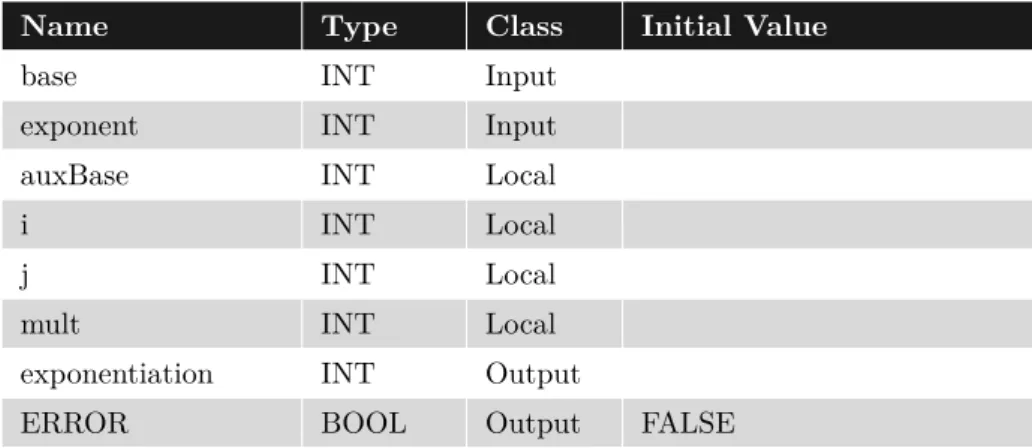
Name Type Class Initial Value
base INT Input
exponent INT Input
auxBase INT Local
i INT Local
j INT Local
mult INT Local
exponentiation INT Output
ERROR BOOL Output FALSE
Table 4: I/O Table of the ST program.
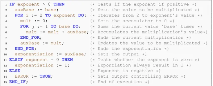
An example of a complete ST program, implementing a POU function block, can be viewed in Code 2, and its correspondent I/O table can be seen in Table 4. The program receives a base and an exponent value, returning the result of the respective exponentiation calculated through sum operations. The execution is easier to follow than the IL program since ST is, as it name hints, a structured programming language.
3.1.2.5 Graphical languages
In the IEC 61131-3 standard there are elements that apply to both the graphical languages, LD and FBD, as well as to the graphic parts of SFC. These common elements are depicted in Table 5.
1 IF exponent > 0 THEN (* Tests if the exponent if positive *) 2 auxBase := base; (* Sets the value to be multiplicated *) 3 FOR i := 2 TO exponent DO: (* Iterates from 2 to exponent’s value *)
4 mult := 0; (* Sets the accumulator to 0 *)
5 FOR j := 1 TO base DO: (* Sums the current value ’base’ times *)
6 mult := mult + auxBase;(* Accumulates the multiplication’s value*) 7 END_FOR; (* Ends the current multiplication *)
8 auxBase := mult; (* Updates the value to be multiplicated *) 9 END_FOR; (* Ends the exponentiation *)
10 exponentiation := auxBase; (* Sets the output *)
11 ELSIF exponent = 0 THEN (* Tests whether the exponent is zero *) 12 exponentiation := 1; (* Expontiation always result in 1 *) 13 ELSE (* Exponent is negative *)
14 ERROR := TRUE; (* Sets output controlling ERROR *) 15 END_IF; (* End of execution *)
Code 2: Example of a ST program.
the connectors are graphical objects which represent a variable, literal or the side of an expression (their counterpart are the continuations).
The set of interconnected graphic elements will form a network. Graphical languages are used to represent the execution flow through one or more networks. These flows are conceptually different, depending on the language implementing them:
• Power flow: analogous to the flow of electric power in an electromechanical system. This is the default flow in a Ladder Diagram (LD), going from left to right.
• Signal flow: analogous to the flow of signals between elements of a signal processing
system. This is the default flow in the Function Block Diagrams (FBD), that will be from the output (right-hand) side of a function or function block to the input (left-hand) side of the function or function block so connected.
• Activity flow: analogous to the flow of control between elements of an organization,
or between the steps of an electromechanical sequencer. This is the default flow in a Sequential Function Chart (SFC), going from the bottom of a step through the appropriate transition to the top of the corresponding sucessor step(s).
Lines and connections Block Connector
Besides the restrictions of flow direction, the evaluation of a network must not start before the states of the inputs have been read and shall not be completed until the state of the outputs have been defined.
The graphical languages and SFC are shown in detail in the next sections.
3.1.2.6 FBD
FBD is a graphical programming language that uses function block diagrams for repre-senting an application program for a PLC. It is based on circuit diagrams, a conventional graphical representation of electric circuits, and the language basic elements are theblocks.
The blocks are a graphical representation of a call statement, encapsulating the al-gorithm and putting in evidence the information flow through the inputs and outputs: the block is activated as its input signals are received in the left-side, processes them and emits the results as outputs in the right-side.
A block may be defined from a set of predefined function blocks — such as timers, counters, etc. — or from POUs, functions or function blocks, defined in the PLC, using any of the other standard languages. For instance, we can see the blocks corresponding to the IL function and ST function block, presented in the previous sections, in Figures 5 and 6.
Figure 5: Block corresponding to the IL function seen in Section 3.1.2.3.
Figure 6: Block corresponding to the ST function seen in Section 3.1.2.4.
Blocks may also be instantiated from the original definition of POU function blocks, since they are stateful objects. The blocks instantiated from the same type will have different names and independent states, being, indeed,variables of the program they are inserted into. A whole POU defined in FBD may as well be seen as a function block to be instantiated as a block in other programs.
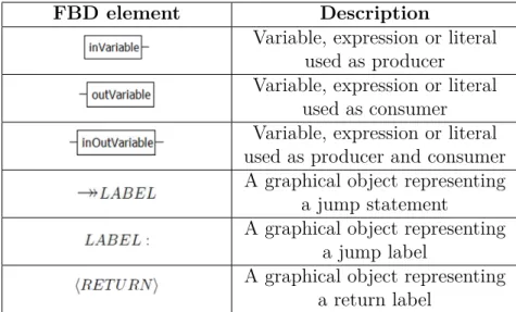
Besides the elements common to graphical languages, FBD introduces some new ele-ments of its own. They can be seen in Table 6. An example of a complete FBD program is depicted in Figure 7.
Figure 7: FBD program example
In the example, a FBD program determines the value of the output variable OUT from the output produced by a Set_Reset Flip Flop (SR) block, whose inputs are the evaluation results of blocksAND and OR, who receives in turn the FBD program inputs IN1, IN2 and IN3 to be evaluated. A connector/continuation is used for the IN3 input, Input3.
3.1.2.7 LD
LD is a graphical programming language using ladder diagrams for representing an application program for a PLC. It is based on relay logic, with horizontalrungs between verticalpower rails executing sequentially.
The rungs represent the sentences of the language, with the inputs in the left and the outputs in the right; the variables are seen as contacts to be energized, evaluation going left to right, top to bottom. Thus a ladder diagram emulates the energy flow between the power rails through the relays. The graphical elements introduced by the language can be seen in Table 7.
FBD element Description
Variable, expression or literal used as producer Variable, expression or literal
used as consumer Variable, expression or literal used as producer and consumer A graphical object representing
a jump statement
A graphical object representing a jump label
A graphical object representing a return label
Table 6: Graphical elements of the FBD language
LD element Description
Left power rail
Right power rail
A contact, closed whenever its corresponding coil or an input which controls it is energized. A “not” contact, open whenever its
corresponding coil or an input which controls it is energized. A coil, energized whenever its rung
is closed. Represents outputs or local variables.
A “not” coil, energized whenever its rung is open.
of the contact corresponding to IN3 is determined, next analyzing the contact of IN4. If IN1’s contact is closed or the contacts of IN3 and ¬IN4 are closed, the rung will be closed ifIN2’s contact is also closed. LDT est’s coil will be energized only if the rung is closed.
Figure 8: Example of a program in the LD language.
LD also has support for the elements of FBD, so a LD program can make use of producers and consumers, as well as blocks. This way the complexity and expressivity of the language can be increased. In Figure 9 we have an example of a more complex ladder diagram, where whether the rungs are closed or not will also depend on the evaluation realized in a FBD block, with inputs (var3 andvar4) received independently of the rung’s execution flow.
Figure 9: LD diagram making use of FBD elements.
3.1.2.8 SFC
SFC element Description
A single step in a SFC sequence, with actions associated. The initial step is marked by a double border. Anaction block is a set of actionsassociated to a step,
whose implementations may be in IL, ST, FBD or LD. A macro stepis a step that embodies another SFC
program.
A transition between SFC elements, with a boolean condition associated.
A jump to a step, macro step or simultaneous divergence. Acts like a step, as its predecessor must be a transition. A selection divergence is used to select one of several partial sequences depending on as many conditions, each
contained in a transition.
Selection convergencesof sequences continue several partial sequences in a common one. Each of the alternate
sequences must have a transition to the first step of the common one.
A simultaneous divergenceis used to activate several partial sequences after transitions.
Simultaenous convergencescombine over a single transition sequences from several steps.
Table 8: Graphical elements of the SFC language
A sequence of steps can be seen in Figure 10. We have S1 as the initial step, and thenceforth the transitions and steps must be organized in such a way that any two steps are connected by one single transition, as well as two transitions must always be separated by one step. As shown in Table 8 there are special elements to aggregate more than one transition, either to (convergences) or from (divergences) a step, which is either of a selection orsimultaneous nature, with the former selecting one of several execution paths and the latter activating or combining multiple execution paths. Thus, considering these convergenceanddivergenceelements, one has that the valid predecessor elements of a step are the ones presented in Figure 11, while the valid predecessor elements of a transition can be seen in Figure 12.
Figure 10: A sequence of SFC steps connected by transitions.
Figure 11: The valid circumstances in which a step can be reached in a SFC program.
Figure 12: The valid circumstances in which a transition can be reached in a SFC program.
Transitions
Flow control
Using the convergence or divergence elements it is possible for the SFC program to alter how the activity flow runs over the sequences of steps. With theselection structures the program may choose between several partial sequences from a step, depending on which of the transitions will be validated — divergence; or represent the alternate sequen-ces that may lead to a step — convergence. With thesimultaneous structures, the activity flow may be split in several partial sequences simultaneously or they can combine to a single transition the flow coming from numerous steps — divergence and convergence, respectively.
Figure 13: A SFC program using selection convergence and selection divergence.
Figure 14: A SFC program using simultaneous convergence and simultaneous divergence.
In Figure 14, however, where we have a similar network but with the simultaneous structures, fromStep1, afterT1 is validated, the three partial sequences will be executed, simultaneously. Then,onlywhen all the predecessors steps of thesimultaneous convergence are active, the activity flow will converge to the evaluation of transitionT4.
Figure 15: A SFC program wrongly using the simultaneous convergence element.
Actions
They can contain either a boolean variable, statements in IL or ST, or networks in FBD or LD, like the transitions’ conditions. Associated with each action there is a qualifier: an attribute that may alter the way in which the action is performed — if repeatedly while the respective step is active, if only once, if during some time, and so on; its default value isN, where no modification occurs.
Example
Name Type Class Initial Value
n1 INT Input
n2 INT Input
in1 BOOL Input
answers ANSWER Local [YES, NO]
higher RESULT Output UNDETERMINED
Table 9: I/O Table of the SFC program.
An example in which actions are associated to steps can be seen in Figure 16; its I/O table is presented in Table 9, with these variables being used in the SFC transitions and actions.ANSWER and RESULT are new types declared for use in the SFC program, the former derived from the Arraytype and the latter from the Enumeration type.
Figure 16: SFC program presenting the discussed elements
1 TRANSITION FROM Start TO Step1 2 := in1;
3 END_TRANSITION
4
5 ACTION Action1 :
6 IF isHigher(n1, n2) THEN 7 higher := answers[1);
8 ELSE
9 higher := answers[2);
10 END_IF; 11 END_ACTION
Code 3: Action1, in ST
its logic condition, the value of the boolean input in1, is equals to TRUE. The action Action1 is associated to Step1, so it will be executed once the activity flows reaches this step. It evaluates whether, from two integer inputs, the first is higher than the second, producing as output the answer YES orNO. A calling to the POUfunction isHigheris made in line 6; its implementation will be seen in the next Chapter, when this example will be retrieved.
3.2
PLCopen
The PLCopen standard (PLCOPEN, 2009) is an effort of the PLCopen Technical Committee to gather all the information of the five different languages of the IEC 61131-3 standard and provide an interface with their supporting tools, as well as the ability to transfer information between different platforms. It is an XML-based standard able to store not just the textual, but also the graphical information of a PLC project, allowing complete translation from a representation to another.
The PLCopen standard structures PLCs in three specific parts: the Project structure, with headers containing general information about the project; theInstancespecific part, representing the configurations of the environment in which the PLC may operate; and the Type specific part, where we have the Program Organization Units (POUs) and the Data Type Elements.
In this section we present Types and other elements of the PLCopen’s XML format in detail.
3.2.1
Variables and Data types
In PLCopen a variable is an element whose main attributes, besides its name, are its type and the values it might receive. The XML element of a variable in PLCopen can be seen in Code 4:
1 <xsd:element name="variable" minOccurs="0" maxOccurs="unbounded"> 2 <xsd:complexType>
3 <xsd:sequence>
4 <xsd:element name="type" type="ppx:dataType"/>
5 <xsd:element name="initialValue" type="ppx:value" minOccurs="0"/> 6 <xsd:element name="addData" type="ppx:addData" minOccurs="0"/> 7 <xsd:element name="documentation" type="ppx:formattedText"
minOccurs="0"/>
8 </xsd:sequence>
9 <xsd:attribute name="name" type="xsd:string" use="required"/> 10 <xsd:attribute name="address" type="xsd:string" use="optional"/> 11 <xsd:attribute name="globalId" type="xsd:ID" use="optional"/> 12 </xsd:complexType>
13 </xsd:element>
Code 4: XML element to a Variable
3.2.1.1 Data Type
It is represented as an XML complex type, so it can be assigned to elements, like the type element in the variable, for instance. Three different groups of possible data types are embodied:
• Elementary types: with the exception of thestring types, which have thelength information as an attribute, the other types contain in the XML element only the name of the type: BOOL, INT, UINT, etc.
• Derived types: In this category are the types of higher complexity, the same
ones mentioned in Section 3.1.2.2, corresponding to the Derived types for PLC programming.
• Extended: In addition to the IEC 61131-3 standard, a datatype can be of the type
POINTER. A pointer is defined by its required base type.
Elementary types
1 <variable name="boolVar"> 2 <type>
3 <BOOL/> 4 </type> 5 </variable>
A boolean variableboolVar, according to the previous code, Code 4, showing an XML variable element, would be of the form presented in Code 5.
Data type elements
New types can be created based on the standard ones. These elements have a name (the name of the new type), the type it is based on (a Data Type) and the initial value associated to the type (a Value). Variables can be typed according to this new type.
A new type, SIDE, based on the data type Enumeration, can be seen in Code 6. In line 1 the name of the new data type is stated, while from lines 2 to 10 the type itself is constructed. In line 3 it is defined its derivation form the Enumeration type, with the definition of the possible values an enumeration of the SIDE type may assume made in lines 5-7.
1 <dataType name="SIDE"> 2 <baseType>
3 <enum> 4 <values>
5 <value name="right_side"/> 6 <value name="no_side"/> 7 <value name="left_side"/> 8 </values>
9 </enum> 10 </baseType> 11 </dataType>
Code 6: XML representation of a new type based on theEnumeration data type.
Derived types
In the interest of space we show in detail only the information about the derived type Array, so the logic behind the data types representation can be understood. The complete specification for all the PLCopen elements is available in the standard.
in terms of a range.
1 <xsd:element name="array"> 2 <xsd:complexType>
3 <xsd:sequence>
4 <xsd:element name="dimension" type="ppx:rangeSigned" maxOccurs="
unbounded"/>
5 <xsd:element name="baseType" type="ppx:dataType"/> 6 </xsd:sequence>
7 </xsd:complexType> 8 </xsd:element>
Code 7: XML element for the Array Type
Thus, an array declared asarrayVar : ARRAY [1..10] OF INT; would be represented in PLCopen as:
1 <variable name="arrayVar"> 2 <type>
3 <array>
4 <dimension lower="1" upper="10"/> 5 <baseType>
6 <INT/> 7 </baseType> 8 </array>
9 </type> 10 </variable>
Code 8: XML representation of an array variable
3.2.1.2 Value
The Value element is organized similarly to Data Type, as it embodies the three different kinds of values that can be assigned to a variable:
• Simple Value: the values that can be represented as a single attribute: the value
itself as a string. It is used for the variables with elementary types.
• Array Value: values as a list of {repetitionV alue ⇒ value} objects, so that