Krzysztof Kołek
∗, Andrzej Turnau
∗FPGA AS A PART OF MS WINDOWS CONTROL
ENVIRONMENT
The attention is focused on theWindowsoperating system (OS) used as a control and
mea-surement environment. Windows OS due to extensions becomes a real-time OS (RTOS).
Benefits and drawbacks of typical software extensions are compared. As far as hardware solutions are concerned the field programmable gate arrays FPGA technology is proposed to ensure fast time-critical operations. FPGA-based parallel execution and hardware implemen-tation of the data processing algorithms significantly outperform the classical microprocessor operating modes. Suitability of the RTOS for a particular application and FPGA hardware maintenance is studied.
Keywords: MS Windows extensions, soft real time operating system, FPGA-based controller
FPGA JAKO CZĘŚĆ ŚRODOWISKA STEROWANIA MS WINDOWS
Uwagę skupiono naWindows – systemie operacyjnym (OS) użytym jako środowisko
po-miarów i sterowania.WindowsOS, dzięki rozszerzeniom, staje się systemem operacyjnym
czasu rzeczywistego (RTOS). Porównano wady i zalety typowych programowych rozszerzeń. W przypadku sprzętowych rozwiązań, proponuje się użycie technologii FPGA, by wykonać szybkie, krytyczne czasowo operacje. Równoległe wykonanie algorytmu oparte na technologii FPGA i sprzętowa implementacja algorytmów przetwarzania danych w sposób znaczący prze-wyższają klasyczne mikroprocesorowe tryby pracy. Badane są: dostosowanie oraz użyteczność RTOS dla wybranych aplikacji i rozwiązania sprzętowe wykorzystujące technologię FPGA.
Słowa kluczowe: rozszerzenie MS Windows, miękkie systemy operacyjne czasu rzeczywis-tego, sterowniki oparte na technologii FPGA
1. Introduction
MS Windows is widely used operating system. A great number of users insist to apply MS Windows in real-time control applications. In many cases the systems work satisfactory, however they may not meet the safety time-critical requirements. If these requirements are realised in a programming manner (under an operating system) then the shortest critical times are defined to be a few or tens microseconds usually. Due to the reconfigured FPGA chips we can reduce these times to a few or tens nanoseconds.
∗Department of Automatics, Faculty of Electrical Engineering, Automatics, Computer Science and Electronics, AGH University of Science and Technology, Kraków, Poland,[email protected],
2. MS WINDOWS and its extensions
As far as a real-time operation is concerned threeWindowsenvironments are tested and compared. In fact, one would rather call it ”a soft real-time” [4]. The following Window applications are examined:
• excited byWindowstimer message (WM Timer), • excited by multimedia event timer,
• Real-Time WindowsTarget (RTWT).
To perform the tests we need a time reference for the measurements. Software timers are not accurate they introduce unpredictable overhead to the measurements. Fortunately, we can use the 40 MHz clock available at the RT-DAC4/PCI board [2]. To measure the accuracy of the timer events the periodic tasks are started in each investigated environments. The only goal of these tasks is read the 40 MHz timer. The timer values serve as the time stamps and allow to estimate the jitter of the periodic task.
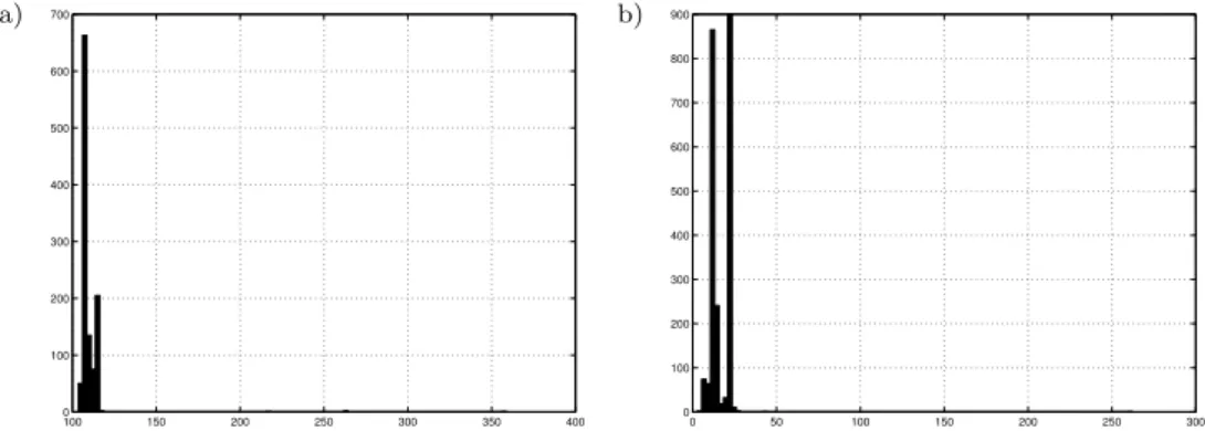
The first experiments related toWindowstimer message have been tested. The periods of the timer is set to 100 ms or 10 ms. For both experiments the several individual tasks were running concurrently. It means that during the experiments MS
Windowswas heavy loaded.
The results in the form of histograms are shown in Figure 1.
a) b)
100 150 200 250 300 350 400 0
100 200 300 400 500 600 700
0 50 100 150 200 250 300 0
100 200 300 400 500 600 700 800 900
Fig. 1.Windowsapplication excited by WM Timer: a) 100 ms-sampling period; b) 10 ms-sampling period
There are two mean values: 109.9601 ms and 15.7571 ms. These values are far away from the desired values: 100 ms and 10 ms. Such an operation is not acceptable for the control purpose. It shows that the time taken for the system to switch from a given task to the task triggered by the timer message is significantly large and does not satisfy measurement and control requirements in the case when the sampling time is below tens of milliseconds.
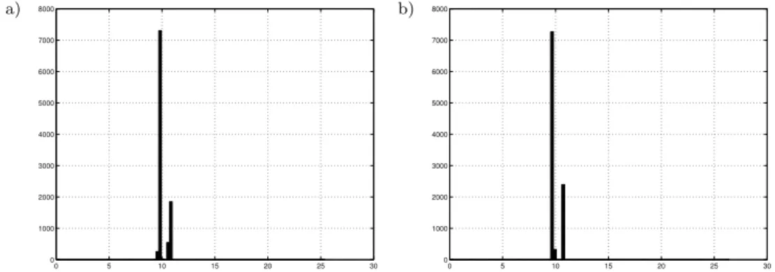
(RT-CON). The graphical results of two similar experiments of the sampling peri-od equal to 10 ms are shown below (see Fig. 2).
a) b)
0 5 10 15 20 25 30
0 1000 2000 3000 4000 5000 6000 7000 8000
0 5 10 15 20 25 30
0 1000 2000 3000 4000 5000 6000 7000 8000
Fig. 2.Windowsapplication excited by multimedia event timer; similar experiments: a) and b) 10 ms-sampling period
The mean values are correct but a large jitter happens occasionally (even 25 ns). The final experiments correspond toWindowsextended to RTWT. The graph-ical results of two experiments excited by the sampling periods equal to 10 ms and 1 ms are given below (see Fig. 3).
a) b)
9.980 9.985 9.99 9.995 10 10.005 10.01 10.015 100 200 300 400 500 600 700 800 900 1000
0.9750 0.98 0.985 0.99 0.995 1 1.005 1.01 1.015 1.02 1.025 200 400 600 800 1000 1200 1400 1600 1800 2000
Fig. 3. Windows application extended to RTWT: a) 10 ms-sampling period; b) 1 ms-sampling period
The mean values are correct. We observe a small jitter. This solution works perfectly except that it does not support majority of the Windows API functions. For example, USB protocol.
the RTWT case which seems to be the most suitable tool almost all the Windows
API functions are not supported.
We can create add-on functionality via extensions to MSWindowswhich may improve to a large extent responsiveness of originalWindows. The primary goal is to minimize pre-emptive and interrupt latency. Unfortunately Microsoft kernels do not provide deterministic response.
Table 1
Benefits and drawbacks of the presented MSWindowsenvironments
Benefits Drawbacks TheWindows application excited by Windowstimer message WM Timer
EachWindowsare supported by the MFC library. All functions from theWindows
application programmer interface (API) operates properly
The average jitter is acceptable. I/O memory space is available due to drivers only
TheWindows application excited by multimedia event timer
The average jitter is acceptable. Nearly all functions from WindowsAPI operates properly For example, support for USB
A large jitter happens
occasionally. I/O memory space is available due to dedicated I/O drivers only
Real-Time
Windows
Target RTWT
Small jitter. Very good time stability
Almost every function from WindowsAPI is not
supported. I/O memory space is available
3. FPGA based time-critical operations
Critical part of a design are shift registers and counters. They should run faster ap-proximately two thirds of the specified toggle rate.
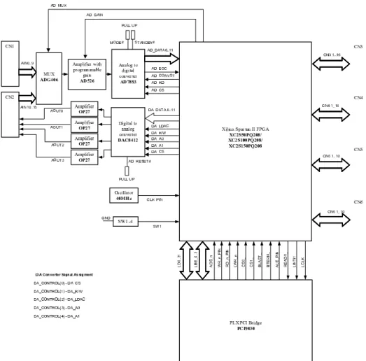
Fig. 4.Block diagram of the RT-DAC4/PCI board (courtesy Inteco Ltd)
One can use a vast number of complex and advanced computer boards equipped with FPGA. We focus our attention to RT-DAC4/PCI board (see Fig. 4) which include two main elements: the PLX9030 PCI bridge and the FPGA chip [3]. The bridge is the local data bus master responsible for data transfer between the PCI and local bus. The local data bus is connected to the FPGA chip. Each analog and digital I/O function of the board must be implemented as a logic part of the FPGA chip. By the computer applications the RT-DAC4/PCI board is visible as a 64 double words located in the I/O address space. An extra 64 double words I/O space is accessible if interrupts are considered. The access to the board resources is done by theinp,inpw
The board can run at synchronous system clock rates of 40MHz applied to syn-chronize user-designed logic. The clock signal (40 MHz) born at the board and con-nected to the FPGA chip generates the local bus clock signal which is asynchronous to the PCI bus clock and is independent to the PC microprocessor clock. It means that FPGA works autonomously. Even the reset signal to the PC does not affect the FPGA operations. These features create a temptation to use an FPGA chip to be applied as safety time-critical device.
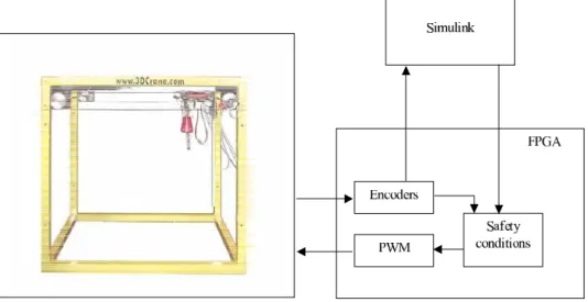
To illustrate safety time-critical operations realized by an FPGA circuit the con-trol of the 3D Crane laboratory system is examined (see Fig. 5). The system can be used to develop even time-optimal control algorithms [5]. The real-time and free of delays operation is guaranteed due to functionality embedded in the FPGA logic.
Fig. 5.Configuration of the 3D Crane measurement, control and safety system
There are several critical constrains related to the crane construction and control. It is strictly forbidden to go beyond the 3D Crane system ranges. The bridge and the cart of the crane must remain inside their working space. The temperature and supply voltage of the power amplifier are permanently monitored and supervised. A violation of an arbitrary constraint rule has to result in a fast (without a delay) reaction of the system. These safety functionality is inserted (configured) directly in FPGA. It is guaranteed that the system responds to a violation of rules within 25 nanoseconds. Beside the critical safety rules the FPGA system is configured to become the interface to sensors (encoders) and actuators (the PWM generators applied to control the DC motors).
configuration shown in Figure 6 is an extended version of the configuration shown in Figure 5. The SoC approach characterizes reach functionality – it means that multiple system components are placed on a single silicon chip [1]. The FPGA circuits contain resources sufficient to implement microprocessors, operational memory, interfaces to measurement and control signals, interfaces to communication channels, signal pro-cessing blocks, etc. One can decompose tasks and implement them as programmes of microprocessors or dedicated logic blocks. In peculiar, we can define the components responsible for time-critical safety operations.
The main benefit of FPGA is its reconfiguration flexibility. It might happens that urgent modifications to a logic are required. In this case we can introduce them in a very fast and relatively simple way. The modifications do not interfere in hardware! Despite that this new implemented functionality is realised by the FPGA hardware.
Fig. 6.System on the Chip configuration
4. Summary
MSWindowsdue to extensions becomes a real-time OS (RTOS). One has to remem-ber thatMS Windowsequipped with extensions can manage to control simple lab-oratory devices in real-time. However, it is not recommended to apply MSWindows
the FPGA logic is proposed. A microprocessor configured in this logic responds to time-critical events independently to the MSWindowsoperation.
References
[1] Kołek K.:FPGA as a Part of Control System. 14th International Conference on Process Control ’03, Strbske Pleso, Slovak Republic, June 8–11, 2003, p. 207, CD [2]RT-DAC4/PCI Board. Users Guide,http://www.inteco.com.pl
[3]Spartan-II 2.5V FPGA Family: Functional description.http://www.xilinx.com
[4] Timmerman M.:Windows NT Real-Time Extensions better or worse? Real-Time Magazin 98–3, pp. 11–19, 1998