ANALYSIS OF BIT GROUPING
ALGORITHM FOR COLLISION
RESOLUTION IN PASSIVE RFID TAGS
KATHEEJA PARVEEN M
Department of Computer Applications, B. S. Abdur Rahman University, Vandalur, Chennai, Tamil Nadu, India
SHEIK ABDUL KHADER P
Department of Computer Applications, B. S. Abdur Rahman University, Vandalur, Chennai, Tamil Nadu, India
MUNIR AHAMED RABBANI M
Department of Computer Applications, B. S. Abdur Rahman University, Vandalur, Chennai, Tamil Nadu, India
Abstract:
Radio-Frequency Identification (RFID) systems consist of radio frequency (RF) tags and networked electromagnetic readers. Check in and Checkout of goods becomes faster and more efficient when RFID systems are implemented. A common issue of all RFID systems is the collision of signals. Since multiple passive tags respond to a query broadcasted by a reader, the reader becomes a recipient of mixture of scattered waves which results in increase in identification delay, communication overhead and unnecessary energy wastage that ultimately shortens the life span of the system. Conventional protocols began their journey from being memoryless; however recent mechanisms are memory oriented. It is also observed that existing approaches perform better when the tag population is optimal. When the population rises exponentially, the utilisation of time slots and energy consumption also rises haphazardly. The anti collision scheme has to be in the mode of “reader inquiring” and “tag answering”. Though Binary Tree, Query Tree, variants of Query Tree, Adaptive Query Splitting and Adaptive Binary Splitting show superiority in minimizing collision, identification delay and transmitting bits, they are no longer memoryless. Simulation studies have shown that idle listening and collision are the main causes for energy consumption. The proposed bit grouping memoryless algorithm is adapted to the characteristics and constraints of an RFID system, i.e. tags with limited power supply and processing capabilities, fixed or mobile readers with better processing capabilities than tags, and the existence of bad behaving eavesdropper readers which might attempt to track the identity of the tags.
Keywords: RFID; Tag Anti Collision Algorithm; Wireless Sensor Networks
1. Introduction
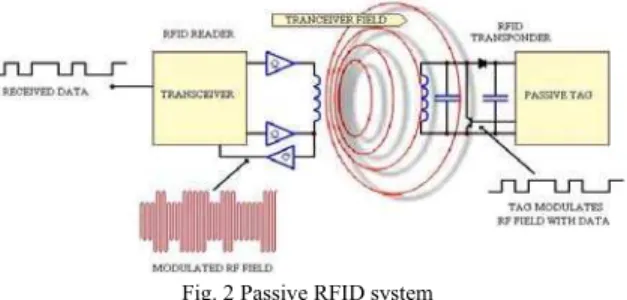
RFID was developed out of the radar experiments and development during the Second World War. The actual date of invention is 1948 but this was followed by decades of development and experimentation before commercial applications were implemented. Toll systems were the breakthrough product for RFID. In a few years, toll systems and government toll collection agencies had spread across the world fuelling the development of the system. RFID system consists of reader (with antenna or coil and transceiver with decoder) and a transponder (an unique active, passive or battery-assisted passive RF tag). The Ultra High Frequency (UHF) reader is a dedicated radio transmitter as well as a receiver. Similar to other devices, the reader generates signals at the carrier frequency around 900 MHz for typical UHF devices and modulates the carrier signal to communicate to the tags. It must selectively receive and amplify responses from tags, and convert the received signal from the carrier frequency down to much lower frequencies.
(a) passive tags (b) semi passive tags (c) active tags
UHF tags are of three types namely passive, semi-passive, and active. Passive tags use the signal received from the reader to power the Integrated Circuit (IC), and vary their reflection of this signal to transmit information back to the reader. Passive tags are the most common in cost-sensitive applications as they need no battery or transmitter, and hence they are very inexpensive. Semi-passive tags, sometimes known as battery-assisted passive tags, use a battery to power the tag electronics, but also depend on a reflected signal for communications. Active tags are full-featured radios with their own transmitting capability independent of the reader.
Passive tags and semi tags follow the communication model of Reader Talk First (RTF), while active are Tag Talk First (TTF). RFID reader also has the capability to mute tags. Passive tags, however, has the potential only to reply the message to the reader, but the capability to communicate within the same group is absent.
Simultaneous reader transmissions and tag transmissions result in collision, as both reader and tag operate with the same frequency band, due to cost consideration. Collision thus experienced causes delay in tag identification, as tags re-transmit their ID’s again for identification which may again cause collision. These collisions are classified as Reader collisions and Tag collisions. Reader collision occurs when neighboring reader interact with the same tag. Tag collisions are experienced when multiple tags are energized by the RFID reader simultaneously and when tags reflect their respective signals back to the reader at the same time. This problem is often observed whenever a large volume of tags are to be read together in the same RF field. In such a scenario, the reader is unable to differentiate the signals received, thus failing in recognition. Readers can detect collision and resolve by interacting, however, low functioning passive tags unfortunately can neither sense a collision nor talk with their neighboring friends to get intimated.
EPCglobal [EPC] and international organization for standardization [ISO] are two bodies that are responsible for laying out RFID standards. If concern towards security is considered as a lower priority over speed and take the risk of presence of an eavesdropper then Class 0 draft protocol should be used as it provides a definite advantage over Generation 2 protocol. In application areas where the risk of consumer identity or privacy theft is high then Generation 2 provides the security but that eliminates the vulnerability of the RFID EPC structure.
The design of anti-collision protocols for RFID system is challenging since the tags cannot communicate with each other directly and may not be capable of storing states of the arbitration process in their memory. Hence, tag collision arbitration protocol suggested for passive tags should feature the following attributes:
(1)Readability: Reader should identify all tags within its range. To add more, these tags can be read only at very short distances, may be a few metres. Passive tags have read range from 0.1 m to 7m. Hence, recognition time must be minimal, as all the more they are mobile. Due to mobility they might not be in the vicinity of the reader after tag ID is half read, when delay in reading time is seen.
(2)Reliability: Tag starvation i.e., tags never getting the opportunity to interrogate with the reader should never be encountered.
(3)Power Consumption: Since passive tags do not carry any battery of their own, and are completely relied only on the energy generated by the reader, the consumption of power must be very minimal.
(4)Computation Complexity: Passive tags have limited computational capacity, no ability to sense the channel, detect collisions, or communicate with each other. Any change in the tag circuitry is directly associated with cost. Hence, complexity must be avoided to the most possible extent, as passive tags are very popular among the crowd of three only because they cost less and durable.
(5)Time Complexity: RFID is a time critical application oriented system, and hence delay caused during tag identification process directly degrades the efficiency of the system. These systems are common in asset tracking industry, with applications ranging from automated checkout, monitoring the medication intake of elders, to reading tagged items in a shopping cart quickly as a customer passes an automated checkout. (6)Message Complexity: Number of bits transactions between the sender (reader) and the receiver
(7)Scalability: Among the different types of tags, passive tags hold a special place in large scale industry based application deployments [Lahiri (2006)]. Hence the RFID reader must anticipate tags in any number in its readable range and still be able to perform better.
Tag orientation also affects the performance of tag reading protocols. If a tag’s antenna is parallel to the reader’s field lines, tags become unreadable [Finkenzeller (2003)]. Thus when readers and tags are randomly deployed, there also arises a possibility that tags can become unrecognized even when they are present in a reader’s interrogation zone. This paper reviews the existing tag collision protocols with their merits and limitations and also proposes bit grouping memoryless algorithm. The proposed algorithm is compared with existing approaches suggested by observing the performance based on identification delay, reader or tag hardware changes, number of bits transmitted, number of collisions experienced and effect on variations in tag population.
The remainder of this paper is organized as follows: Section II narrates existing tree based approaches. Section III elaborates the proposed bit grouping memoryless algorithm and demonstrates its working procedure with an experiment. The simulation results are shown in Section IV. Finally, the concluding remarks are mentioned in the last section.
2. Related Work
Passive RFID tags face some special problems that are not encountered in most other digital radio systems. A very important issue in RFID systems with passive tags is complexity, and computing and transmitting capacity of tags in the identification process. These tags are cheap and dumb, and thus only changes in amplitude of the reader signal can be used. Moreover, advanced modulations like phase-shift keying or quadrature-amplitude-modulation (QAM) are not available. Considering the limitations discussed, tag anti collision protocols are categorized into Space Division Multiple Access (SDMA), Code Division Multiple Access (CDMA), Frequency Division Multiple Access (FDMA) and Time Division Multiple Access (TDMA).
SDMA protocols are expensive and require complex antenna designs. While CDMA apart from being expensive, they are also in need of high energy source. On the other FDMA, requires a complex RFID reader as tags talk on one of the predefined frequency channels. The last of the four is TDMA, who constitute a larger group of anti collision protocols. TDMA protocols are subdivided as Reader Driven (ie., RTF) and Tag Driven (i.e., TTF). RTF are further classified as Aloha (Probabilistic), Tree based (Deterministic) and Hybrid (combination of Aloha and Tree based) protocols. Variations of tree based protocols are influenced by either Query Tree (QT) or Binary Tree (BT) protocol. This section introduces the methodology of some of the Aloha based protocols such as aloha, slotted aloha, and frame slotted aloha and Tree Based Protocols BT, QT and variants of QT, Adaptive Query Splitting (AQS) and Adaptive Binary Splitting (ABS) [Myung et al (2007)] and Adaptive Splitting and Pre-Signaling (ASPS).
2.1.Probabilistic based protocols
Following discussions are based Aloha protocols. The variants can be listed as (1) Pure Aloha (PA)
(2) Slotted Aloha (SA) (3) Frame Slotted Aloha (FSA)
2.1.1. Aloha and its Variants
BFSA muting, BFSA non muting early end and BFSA muting early end. In DFSA [Cha and Kim (2005)], the reader is provided with the flexibility to vary the frame size. During collision, the reader increases the frame size until an efficient number of tags can be detected. As long as tags are detected, it decreases the frame size and so on. Limitation of DFSA [Vogt (2002), Auto-ID Center] is that the frame size is bounded. Enhanced DFSA [Choi (2007)] divides tags into M groups when the number of tags is greater than the maximum frame size. But implementing this approach increases both system cost and complexity.
2.1.2. Conclusions
PA transmits its tag ID after a random time to the receiver. A delay is set in case of a collision. SA instructs tags to transmit their ID’s in the synchronized time slot. During collision, tags attempt to reply after a random number of slots. BFSA is permits the tag to talk only once in a fixed frame. While DFSA varies the frame size based on the tag population. Implementation of PA is the simplest of all the others. PA requires only a timer, while the others require a random number generator and synchronisation circuits. DFSA additionally require tags to generate short pseudo IDs for tag recognition and estimation. When concerned with heavy tag population, PA and SA face a number of collisions. Identification delay is highest in PA, while PA with fast mode and muting takes the least time among PA and SA variants. Muting early end of DFSA and EDFSA takes a lesser identification time to read a tag successfully while BFSA takes a longer time. PA and its variants are an ideal implementation solution if low cost is the main concern. If the measurement takes account of system performance for a heavy dynamic tag population then a sacrifice to the cost has to be made, as DFSA and its variants that show better system efficiency and accuracy are costlier than PA.
2.2.Tree Based Protocols
In tree based protocols, reader repeatedly splits the tags into two groups, until a group contains only one tag. An identification process can be illustrated as a process of creating and searching a tree where a leaf node in the tree represents a readable or a collided slot, and the intermediate node depicts a collided slot. These protocols are highly applauded as they eliminate tag starvation. They are represented in the following classifications.
(1) Tree Splitting (TS) (2) Binary Search Tree (BST) (3) Query Tree (QT)
(4) Bitwise Arbitration (BTA)
Among the four, QT and are common emblematic approaches of tree based algorithms suggested recently. Though QT and BT have similarities in the construction of a tree, they differ in tree maintenance and grouping. For UHF RFID protocols, EPC class 1 protocol [EPC Global Version 1.0.1] uses a bin-based Binary Tree algorithm; EPC class 1 Gen 2 protocol [EPC Global Version 1.0.9] uses a “Q”-protocol which is based on Dynamic Frame Slotted Aloha (DFSA) algorithm; ISO 18000-6 type A protocol uses DFSA algorithm; ISO 18000-6 type B protocol uses Binary Tree algorithm. These tree based protocols require tags to have muting capability, i.e., tags are muted after they are successfully identified by the reader. Adaptive Query Splitting (AQS) and Adaptive Binary Splitting (ABS) [Myung et al (2007)] protocols proposes to improve performance by utilising the information of tree in the previous cycle.
2.2.1. Tree Splitting Algorithms
These algorithms are introduced by Capetanakis (1979) can be used for RFID arbitration, in conventional multi access systems. Suggestions made by Hush and Wood (1998) in the following steps show how set of tags within the range of Reader can be uniquely identified using the idea of Tree searching Algorithm.
Step 1: Split groups of colliding tags into B disjoint sets (B > 1) Step 2: Repeat Step 1, till the subset contains only one tag
Step 3: Once the subset with one tag is identified, resolve the next subset in FILO approach.
2.2.2. Binary Search Tree
The working algorithm of BST is as follows:
Step 2: Tags send (k+1)th bit if the first k bits of tag IDs matches.
Step 3: If the received bits collide, add 0 or 1 to the extended prefix and retransmit to the tags. If they do not face collision, the received bit is attached to the prefix for the next prefix. If there is no response, the branch is ignored. If a collision occurs at the last bit of the tag IDs, the reader assumes there are two tags since tag IDs are unique.
Step 4: Reader repeats the procedure until all branches are searched.
Even though BST is very efficient, it is not advisable for passive tags, as it demands the tags to remember the previous bits read which is infeasible for low cost passive tags.
2.2.3. Enhanced BST with Cut Through
The operation in [Tsan (2006)] is summarized here with
Step 1: Initialization: 1. Construct a binary search tree for all possible nodes. 2. Cut the intermediate nodes with less than one existing node.
Step 2: Insertion: Perform split operation if there are new RFID devices
Step3: Deletion: Cut-through the intermediate nodes with less than one existing node
Step 4: Cut-through operation: If the values of a node and its parent are the same, combine these nodes and update the label in the new edge.
Step 5: Spilt operation: If there is a new RFID node, search the cut-through tree and increase the counter value from the root to the leaf node. If no suitable branch links can be found, generate the branch and set the value to one.
The cut through operation shortens the search, consumes less power and complexity involved in implementation is simple.
2.2.4. Query Tree
QT algorithm consists of rounds of queries and responses [Choi (2007)], [Shih (2006)] interchanged by Readers and Tags. The QT algorithm is an improvement from BTWA. The difference between them can be observed in the following steps:
Step 1: Reader is given the freedom to choose the bit ‘0’ or ‘1’. Reader transmits k-length prefix.
Step 2: Tags send from (k+1)th bit to the end bit of tag IDs if the first k bits of tag Ids are the same as the prefix. Step 3: If there is a collision, the extended prefix attached ‘0’ or ‘1’ to the prefix is retransmitted. Furthermore, if there is no collision, the reader identifies a tag corresponding to the detected ID, which is the connection of the prefix and the response.
QT requires very less tag circuitry. It is a memoryless tag identification protocols in which the tags do not have to remember anything. However, when the number of k bit responses from the tags is in rise, the QT will end up in heavy collision.
2.2.5. QT Short Long
In order to overcome heavy collision in QT, when the number of k-bit responses are more, QT – Short long (QTsl) [11] is proposed. QTsl is similar to QT except for a few modifications. This protocol helps to reduce the number of bits transmitted from tags. Let there be n tags to be identified. The expected reader communication complexity of QT-sl protocol is at most 3.89kn + 3.89n. The expected tag communication complexity of QT-sl protocol is at most 2:21logn
2
+ k + 4.19. 2.2.6. QT Incremental Matching
QT- Incremental Matching (QTim) is analogous to QTsl. The tag communication complexity is same for both the protocols, but the number of bits transmitted is reduced. This protocol requires a tag to remember the bit position of the prefix it has matched so far. Hence, it can be no longer be called as memory-less. Each tag has a bit marker b € {1, . . . k}. When the tag is active, upon receiving the query, the tag matches the query string starting from bit b. If identical, then bit marker b is incremented by 1. When it mismatches, tags would go to transient state. The expected reader communication complexity of QT-im protocol is at most 4.42nlogn
2
2.2.7. Adaptive Binary Splitting
Adaptive Binary Splitting (ABS) protocol [5] is proposed to improve ISO/IEC 18000-6B protocol by maintaining tags’ counter of the last interrogation round to speed up the recognition procedure. ABS uses 2 counters - Allocated Slot Counter, ASC (similar to ISO/IEC 18000-6B protocol), and Progressed Slot Counter, PSC (to store the number of successfully identified tags). These counters are initialized to 0 in the first round, but only PSC is reset to 0 as the rounds progress. Tags with ASC = PSC are allowed to transmit their tag IDs. When there is only one response, the tag can be identified and each tag increments counter PSC by one. When there is no response, all tags with ASC > PSC decrements counter ASC by one. When collisions occur, those tags with ASC > PSC increases ASC by 1, while the tags with ASC != PSC, a random binary bit generated is added to ASC. But the probability of generating 1 or 0 of each tag is 50%. For example, in a 3-bit binary sequence, only 011, 101, and 110 each has one 0. In case of a collision, only n/2n x 100 % percentage is available for the next timeslot. In other words, the next timeslot can either be an idle timeslot or a collision timeslot again. An idle timeslot here by will waste two timeslots in the reading process. Hence, the probability of generating “1” and “0” is the main factor which affects the performance of ABS.
2.2.8. Adaptive Splitting and Pre-Signaling
Adaptive Splitting scheme [5] estimates the number of k colliding tags and splits them into k groups to speed up the identification process. In the first phase, the adaptive splitting scheme obeys ISO/IEC 18000-6B protocol until the first tag is identified successfully. It then enters the second phase, in which the reader estimates the number of colliding tags of a specific counter value. The algorithm splits tags into N groups such that each group has exactly one tag for identification by recursively applying ISO/IEC18000-6B protocol. By the help of pre-signaling scheme, the number of messages sent between a reader and tags can be significantly reduced, which in turn shortens the identification procedure latency. Simulation results show that ASPS reduces the number of collisions, number of messages sent by the reader, tag identification delay. However, ASPS requires the tag to modify the random number generator design on the tag circuit. Also, the implementation of a complex algorithm such as ASPS in a reader adds vulnerability to its strength.
2.2.9. Bitwise Arbitration
BTA requests tags to send their IDs bit by bit from Most Significant Bit (MSB) to Least Significant Bit (LSB). The bits replies of BTA are synchronized i.e., when multiple tags respond the same bit, occurrence of collision is completely eradicated. Bit position where collision has occurred can also be easily detected by recognizing the signal collision received at the reader. ID BT stack (ID BTS) [Bo et al (2006)] constructs a binary tree with height “k”. The reader in this approach uses a stack to store tags position on the tree, while the tag remembers the counter to know the depth of the readers’ stack.
2.2.10. Other Variants
Proposal made in [18] differs with QT by using a 16 bit random number generator. Once the random number is identified, the reader requests the tags to respond their complete tag ID. Hybrid Protocol works by combining tree and Aloha protocols. Tree slotted aloha (TSA) [Bonuccelli et al (2006)], Hybrid Query Tree Protocols [Ryu et al (2007)], Frame Query Tree protocol [Shin et al (2007)], Hybrid Randomized Protocol [Namboodiri et al (2007)], Hash Tree protocol [Zhang (2007)] are its variants.
2.2.11. Conclusion
require low functional and less expensive tags. However, since they use prefixes, their performance is sensitive to the distribution of tag IDs.
EPC global Class 0 standard uses ID BTS while EPC global Class 1 Gen 2 and Philips U Code standards are implemented in QT. Philips I Code standard utilise DFSA protocol. The tag cost gradually increase from QT, TSA, BST to BTA. Optimum channel utilisation is 43% in case of tree protocols, 18.4% for Pure Aloha, 36.8% for BFSA and 42.6% for DFSA. Identification delay is comparatively less in tree protocols when the tag population is high, while Aloha shows the same result only in low density. Time complexity of QT and TS is O(n), while BST takes O(log n) and BTA consumes O(2k).
Energy wastage is highest in PA while the lowest among PA and its variants is PA with fast mode and muting. Even though AQS and ABS are ambitious to eradicate collisions and lessen identification delay has moved their focus from passive tags to be no longer memoryless. QTim which shows appreciable reduction in tag communication complexity when compared to other variants of QT, also turn out to be a memory oriented protocol. AQS which takes an upper hand to reduce collision has introduced a new problem of idle cycle production. TSA shows higher system efficiency when battled with DFSA, EDFSA and QT. Aloha protocols are mainly used in LF and HF RFID systems, where Tree protocols can be commonly seen in UHF and microwave RFID systems. If energy is the main constraint, then choosing Hybrid randomized protocols becomes the right choice. Number of collisions is lower in HQT when talked with QT protocols. Studies have shown that existing anti-collision protocols are deficient in identifying tags in an energy efficient manner. Since there is a clear need for such algorithms, the proposed bit grouping algorithm promises to be energy efficient.
3. Proposed bit grouping algorithm
An important responsibility of RFID applications is the fast and reliable identification of multiple tagged objects simultaneously, assuming that the exact number of tags is not known in advance. The tag identification process is a continuation of many reading slots, which consist of reader’s queries and tag’s replies. During bit transmission from tag to reader, RF signal for bit “1” and bit “0” are different. Hence when the reader receives a signal with two different RF’s, the reader will understand that a collision has occurred. When multiple tags exist in the same reader’s readable / interrogation range, tags may begin responding the query as soon as they are energized. Simultaneous response from different tags may result in collision. The anti-collision protocols proposed in recent years may not be directly applied for implementation due to various limitations as discussed earlier.
Random number grouping [Wang et al (2009)] suggested in earlier research papers do not serve the purpose of avoiding collisions. This kind of grouping only splits the tags into different sets, but does not take care of anything further. Instead of receiving a “Hello” message from a team of “n” tags, it receives from “m” (m<n) tags, and the reader in both cases fail to understand the response, due to signal collision. NEAA [Yuan-Hsin et al (2010)] proposes the idea of counting the number of bit 1’s (or) 0’s present in a tag id. Those tags who match the total count of bit 1’s or bit 0’s form a group, and follow up their identification process group by group. Consider a scenario where there are two tags having tag Id’s 1001 and 0110 joining hands together to form a group, as their number of bit 1’s match. It is observed from the tag Id’s that collision occurs at every bit, and hence uniting these two tags may not solve the problem. From these discussions, it is clear that tag grouping formed should prevent collisions inside the group as far as possible.
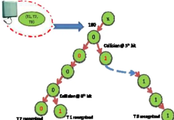
Bit grouping algorithm proposed in this paper helps to prevent collisions to an extent inside the group. The reader first request tags to respond their complete ID. From the responses by tags, the reader identifies collided and collision – free ID bits. Let A (010), B (110) and C (100) be the tags present in the readable range. Then, the resultant of tags response is “XX0”, indicating that the first two have faced a collision. The groups are then formed based on the thorough study of the tag ID’s present. The algorithm instructs the reader to enquire tag’s first bit. If there exists, few tags with first bit as “1” and the rest with first bit as “0”, then it is a clear indication for the reader to experience signal collision, due to the recipient of two different signal frequencies. The reader then instructs the tags to form disjoint groups with a criteria that the first “b” bits remain the same. The groups begin their conversation one by one, while others remain unspoken. Reader queries the tags to respond their (b+1) bit. In case a collision occurs at this level, the reader instructs the same procedure to be followed. Since the number of bits is known to the reader, it queries until the tags are read completely. Since the number of bits present in a tag is known to the reader, the reader terminates if the leaf node has reached a depth level of “n”.
Let T denote a set of Tag ID’s represented in a binary number sequence {T1, T2, T3, T4, … Tn}, where “n”
denotes the number of Tags, present in a cluster in the readable range of a Reader R1. Let the length of each tag
say Ti be “l”. Since the Tag ID’s assigned to each Tag are unique, any Ti≠ Tj. Assume the Tag ID’s for T1, T2
by these tags will be XX0X. It is clear from the Manchester Code, that the Reader R1 has diagnosed a collision
as the combined signals from T1, T2, T3 in the 1st, 2nd and 4th bit are received with two different frequencies. In order to implement the “bit grouping” algorithm in the example discussed for Tags T1, T2 and T3, we consider b = 2. The reader instructs the tags to group themselves based on the tags’ first and second bit being “00”, “01”, “10” and “11”. Observing the tag ids (T1, T2 and T3), two groups are formed, with b bit tags as “01” and “10”. Since the third bit faces no collision, the tree is constructed with its third node as 0. The algorithm dissolves the group “01”. Since the (b+1)th bit i.e., 3rd bit has not faced collision. The reader moves on to query the next bit. Since a collision occurs at the next bit, the tree is branched out with “0” in the left node and “1” at the right side of the tree. Hence, tags T1 and T2 are identified. Similarly, T3 will also be recognized by the reader. The following lines explain the pseudo code from Reader’s end to implement bit grouping algorithm.
Pseudo Code for Reader and Tag operations
1. main
2. while (find_bit(k) <> 2)
3. array[k] := array[k] + find_bit(k); 4. k := k + 1;
5. end while
6. create_group_tags(k); 7. dissolve_groups(k); 8. end main
9. function find_bit (int position) 10. for all tags[j]
11. if j = 0 then
12. bit := tag[j].id[position]; 13. continue;
14. end if
15. if bit < > tag[j].id[position] then 16. bit := 2;
17. return bit; 18. end if 19. next 20. return bit; 21. end function
22. function create_grouptag( int bitposition) 23. for all tags[i]
24. j := bitposition; 25. count := 0; 26. if ( j <= total_bits) 27. if (tag[i].id[j] == 1) then 28. count := count + 1; 29. end if
30. end if
31. if not group_count exist then 32. create array group_count; 33. group_count := tag[j]; 34. else
35. group_count := group_count + tag[j]; 36. end if
37. next 38. end function
39. function dissolve_groups(int k) 40. for all groups [ ]
42. if ( find_bit(j) < > 2) then 43. array[j] := array[ ] + find_bit(j); 44. j := j + 1;
45. else
46. create array = new array_j[total_bits]; 47. array_j := find_bit(j);
48. end if 49. next 50. next 51. end function
4. Experimental Analysis
Consider a 8 bit Tag ID as shown in table I containing the tags named as T1, T2 … T10 and their corresponding Tag IDs. Let the reader be named as R1. As soon as R1 emits radio waves, tags (T1, T2 … T10) present in the electromagnetic zone get energized. The tags send their complete ID to R1. The resultant Manchester code at the readers end is “XXXXXXXX”. Thus it is clear by observing the code, that collision has occurred at every bit, and hence tree construction cannot take place at this stage. The reader requests the tag(s) to send its first bit. Tags T1, T2, T3, T4, T5, T7, T8 and T9 respond bit “1”, while the others (T6, T10) respond bit “0”, hence resulting in collision again.
For optimal grouping the value of “b” is chosen as 4. The groups are formed based on the 1st, 2nd, 3rd and 4th bit taking the values “0000”, “0001”, “0010”, “0100”, “1000”, “1100”, “0110”, “0011”, “1110”, “0111”, “1001”, “1010”, 1011”, “1101”, “0101” and “1111”. Thus according to table 1, the number of groups that are formed is 4. Fig. 3 shows a pictorial representation of the groups formed. Group “1000” has tags T1, T7 and T8. Group “1100” has tags T2, T3 and T5. Group “0010” has tags T6 and T10. Group “1111” has tags T4 and T9. The working bit grouping for the following groups is discussed in the following tree illustrations.
Identification of Group “1000”
The reader starts with group “1000”. A tree is constructed for the bits “1000”. The reader summons the tags in the group, to respond their 5th bit. Due to the occurrence of collision, the tree is split, by adding “0” to the left and “1” to the right at level 5. The tree is partitioned as the reader understands that there are few tags with bit “0” and few with bit “1” at level 5.
Fig. 3 Group Construction Table 1. Tag ID available in the reading range
Tag Name
Bit 1
Bit 2
Bit 3
Bit 4
Bit 5
Bit 6
Bit 7
Bit 8
The reader proceeds to query those tags who has recently responded “0” as their 5th bit, to reply their 6th bit. Fortunately, since existence of collision was unseen, the reader advances to the seventh bit. The reader makes it way to the next bit. Collision occurs at the 8th bit, and the tree creates 2 new child nodes. Since the level 8 is reached, the reader stops querying anymore. Tags T7 and T1 are thus recognized. Possibility of received different signals for the tag that had their 5th bit as “1” is absent, the reader happily grows the tree step by step, and towards the 8th bit the reader recognizes tag T8. Fig. 4, 5 and 6 illustrate the tree construction to identify other tags.
Fig.5 Group “1100” construction Fig. 6 Group “0010” construction
Fig. 7. Group “1111” construction
The following lemma can thus be formulated.
Lemma 4.1. Maximum number of groups that can be formed is equal to the number of groups when b is equal to the number of bits present in a tag ID.
Proof. Assume that the length of ID is n, where n≥1. Then the maximum number of unique tag ID’s that can be formed are 2n. For example if the length of tag ID is 4, then the number of unique tags that can be formed is 24 = 16. Thus if b = number of tags, then 16 groups can be formed, since tag IDs are unique.
□
Lemma 4.2. Number of groups formed is directly proportional to the value of “b”.
Proof. The number of groups that can be formed is dependent on the value of “b” chosen for grouping. Considering the example discussed in Lemma 1, if b takes the value 2, then number of groups that can be formed becomes 4. However, if the value of “b” is 4, then the number of groups becomes 8.
□
Lemma 4.3. Number of groups is inversely proportional to the number of tags present inside a group.Proof. This lemma is an extension of the previous lemma 4.2. If the number of groups increases then it is found that the number of tags decreases proportionately. For 24 tag IDs, if number of groups is 4, then the maximum number of tags that can be present is 4, and for 8 groups, the number of tags is only 2.
□
Lemma 4.4. Number of collisions is directly proportional to the number of tags present in a group.Proof. When the number of tags inside a group decreases, the number of collisions that can arise inside a group will eventually decrease. If the number of groups is 8 for 24 tag IDs then the number of tags inside a groups is 2. Similarly if b is 4, then maximum number of tags is 4. It is obvious that number of collision decreases if the number of tags decreases. If the number of tags is 2 for 8 groups then, and the collision occurs at the second bit, then the reader analyses each tag individually, thus avoiding collision completely thereafter.
□
5. Performance Analysis of bit grouping
In multi-access protocols, the major criteria for performance evaluation include throughput, packet delay, and stability. However, in RFID arbitration, the total time consumed to identify all tagged objects successfully and to account for the consumption of power as a result, is more relevant. To evaluate the efficiency and performance, total time slots taken to discover the tags and average identifying time consumed for recognition are calculated, and the results are compared with Binary Search Tree, QT protocols, Adaptive Binary Splitting and IDS. Length of time slot is the summation of processing time required by the reader, processing time required by the tag, time required by the reader to send a query to the tag and finally the time taken for the tag to respond to the reader. To evaluate the interaction time of the reader to tag and vice-versa, is difficult, and is dependent on the way the IC is being designed. Hence, as calculated in earlier research papers, the length of a time slot will be the summation of processing time taken by reader and tag alone. Hence, Total Time Slot = (No of Time Slots required for identifying all Tags) / Number of Tags i.e., (T0 + T1 + … + Ti + … TT(N)) / N)
5.1.Terrain Setup
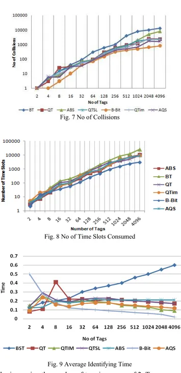
Simulation is performed by increasing the number of tags in powers of 2. To commence, the algorithms (BST, QT, QTSL, QTIM and Bit Grouping) are evaluated when the number of tags is 2, later increased to 4, 8, 16, 32, 64, 128, 256, 512, 1024, 2048 and 4096. Number of collisions that took place, total time slots and the average identifying time are calculated for each increase in the tag population. In general, when the number of tags increases, time taken to identify gets longer and tag collisions are experienced more often. Ambition to prevent collisions by ABS and AQS has also resulted in reduced identification delay than BT and QT. As seen in Fig 7, the proposed Bit Grouping performs much better than AQS and ABS. It is noteworthy that Bit grouping is able to achieve this target of reduced collision by being memoryless. AQS during simulation has generated a number of idle cycles than others due to additional queries in order to produce fool-proof in recognizing all tags. When tags are stable in the readers range for long, BT and QT protocols often experience tag collision. Bit grouping, on the other hand, shows its ability by reading from the last frame as followed by AQS and ABS. Time spent by Bit Grouping on identification is comparatively less.
In real scenario, the choice of implementing a particular algorithm is based on various factors namely cost, time complexity, read accuracy rate. Aloha and its variants – Slotted Aloha and Frame Slotted Aloha can be commonly seen in real time set up as the implementation steps are at ease. Polling protocol is suggested when cost is the company’s main consideration. Bit Grouping can be considered for implementation in real scenarios
Fig. 9 Average Identifying Time Fig. 8 No of Time Slots Consumed
as they are cost – effective, needs minor change in the existing set up, tag can remain memoryless as they are currently.
6. Conclusion
One of the limiting factors for RFID systems is the constraint on memory and computation capabilities, to account for the low manufacturing costs. Passive tags do not have sensing capabilities to detect collision, nor can they communicate with other tags directly. Due to their short radio range, the tag replies arrive almost simultaneously at the interrogator as well as the communication of interrogator with the tag. The tags are consequently limited to very simple calculations. RFID system have major constraints like the reader at any time “t” is unaware of the number of tags available in its interrogation range, mobility in tags, and tag’s limited resources namely power, memory and computation ability. While prior research focused on the anti-collision problem in wireless communication systems, passive RFID systems deserve special attention. The limited power supply for tags makes it infeasible to establish the communication among the tags to coordinate their scattering behaviors. The proposed Bit Grouping algorithm can be implemented in the existing system, without any major change. When compared to existing protocols viz., AQS, ABS and QTim who show appreciable results, Bit grouping offers an improvement without any additional memory or burden to tags. The algorithm checks for collision bit by bit, rather than discovering the occurrence of collision towards the end. Simulation results shows that as the number of tags increases in the reader’s readable range, bit by bit collision checking gives an upper hand in reducing the number of collisions, minimizing the delay time and the number of time slots. Wireless communication channel collision of RFID system is a key issue that affects the pervasive application of the system, especially for passive RFID system due to the constrained communication ability and energy supply of tags.
References
[1] Abramson N (1970), The aloha system – another alternative for computer communications, in Proceedings of Fall Joint Computer Conference, AFIPS Conference, vol 40, pp 281-285.
[2] Bo F., Jin-Tao L., Jun-Bo G., and Zhen-Hua D. (2006), “ID-binary tree stack anti-collision algorithm for RFID,” in Proc. 11th IEEE Symposium on Computers and Communications, (Sardinia, Italy), pp. 207–212.
[3] Bonuccelli M. A., Lonetti F., and Martelli F. (2006), “Tree slotted Aloha: a new protocol for tag identification in RFID networks,” in
International Symposium on on World of Wireless, Mobile and Multimedia Networks, (Niagara-Falls, USA), pp. 603–608. [4] Capetanakis (1979), Tree algorithms for packet broadcast channels, IEEE Trans. Informat. Theory 25, pp 505–515.
[5] Cha J. and Kim J. (2005): “Novel Anti-Collision Algorithms for Fast Object Identification in RFID System,” IEEE Proc. 2005 11th Int’l Conf. Parallel and Distributed Systems (ICPADS), vol. 2, pp. 63-67.
[6] Choi J. H., Lee D., and Lee H. (2007), “Query tree-based reservation for efficient RFID tag anti-collision,” IEEE Commun. Lett., vol. 11, no. 1, pp. 85–87.
[7] Choi, D. Lee, and H. Lee (2007): Query tree-based reservation for efficient RFID tag anti-collision, in: IEEE Communications Letters, vol. 11, no. 1, pp. 85–87
[8] EPC global, “Electronic product code.” http://www.epcglobalinc.org/home/
[9] EPC Global. 860MHz~930MHz Class I Radio Frequency Identification Tag Radio Frequency & Logical Communication Interface Specification Candidate Recommendation, Version 1.0.1
[10] EPC Global. EPC™ Radio-Frequency Identity Protocols Class-1 Generation-2 UHF RFID Protocol for Communications at 860 MHz~960 MHz Version 1.0.9
[11] Finkenzeller K. (2003), RFID Handbook , Fundamentals and Applications in Contactless Smart Cards and Identification. John Wiley and Sons Ltd
[12] Hush, C. Wood (1998): Analysis of tree algorithms for RFID arbitration, in: IEEE International Symposium on Information Theory, 16–21 August, p. 107.
[13] ISO, “RFID Standards.” http://www.iso.org/iso/search.htm?qt=RFID&published=on&active tab=standards.
[14] Myung, W. Lee, J.Srivastava and T. Shih (2007), Tag Splitting: adaptive collision arbitration protocols for RFID tag identification, IEEE Transactions on Parallel Distributed Systems, 18(6), 763-775, 2007.
[15] Namboodiri V. and Gao L. (2007), “Energy-aware tag anti-collision protocols for RFID systems,” in Fifth Annual IEEE International Conference on Pervasive Computing and Communications (PerCom), (NY, USA), pp. 23–46.
[16] Roberts L.G (1972), Extensions of packet communication technology to a hand held personal terminal, in proceedings of Spring Joint Computer Conference, A FIPS Conference, vol. 40, pp 295-298.
[17] Ryu J., Lee H., Seok Y., Kwon T., and Choi Y. (2007), “A hybrid query tree protocol for tag collision arbitration in RFID systems,” in
IEEE ICC, (Scotland), pp. 5981–5986.
[18] Shih D.H., Sun P.L, Yen D. C., and Huang S.M. (2006): Taxonomy and survey of RFID anti-collision protocol, in: Computer Communications, vol. 29, no. 11, pp. 2150–2166
[19] Shin J.-D., Yeo S.-S., Kim T.-H., and Kim S. K. (2007), Hybrid Tag Anticollision Algorithms in RFID Systems. UK: Springer Berlin / Heidelberg.
[20] Tsan-Pin Wang (2006): Enhanced Binary Search with Cut-Through Operation for Anti-Collision in RFID Systems, in: IEEE Communications Letters, Vol. 10, No. 4, p 236- 238
[21] Wang Ya-qi, Jiang Ping and Wang Jiang (2009), “Frame slotted aloha with grouping tactic and binary selection for anti-collision in RFID systems”, Journal of China Universities of Post and Telecommunication, 16(4), pp. 47-52.
[22] Yuan-Hsin Chen, Shi-Jinn Horng, Ray-Shine Run, Jui-Lin Lai, Rong-Jian Chen, Wei-Chih Chen, Yi Pan and Terano Takao (2010), “A Novel Anti-Collision Algorithm in RFID Systems for Identifying Passive Tags”, IEEE Transactions on Industrial Informatics, Vol. 6, No. 1, pp 105-121.