Available Online at www.ijecse.org ISSN: 2277-1956
Analysis of Throughput GTS and SDS in IEEE
802.15.4
Abhinav Singh 1, Pankaj Kumar Patel 2, Dr. P. C. Jain 3
1 ,2 ,3, School Of Electronics, Centre for Development of Advanced Computing, Noida, India Email [email protected],[email protected],[email protected],
Abstract- the current IEEE 802.15.4 standard restricts the beacon enabled approach to star networks, while they support multi-hop networking in mesh but with no synchronization. In this paper there is proposal of a GTS with superframe scheduling for the chain network and throughput is observed.
Keywords- SDS; GTS; PNC
I-Introduction
The IEEE 802.15.4 [1] MAC protocol supports two operational modes: the beaconless mode, in which node stay active all the time, and the beacon mode, in which beacon frames are periodically sent by coordinators to synchronize sensor nodes. The advantage of this synchronization scheme is that all nodes can wake up and sleep at the same time allowing very low duty cycles and hence save energy. In addition, when the beacon mode is used, nodes can use Guaranteed Time Slots specifically designed to fulfill application’s QoS requirements but due to beacon frame collision beacon mode is limited.
There can be up to three types of periods in a superframe: the contention access period (CAP), the contention-free period (CFP), and the inactive period .The combination of CAP and CFP is known as the active period. The active period is divided into 16 equal time slots. The beacon frame always starts at the beginning of first time slot. There can be up to seven GTSs in CFP. Each GTS can occupy one or more time slots. A superframe may optionally have an inactive period.
Figure 1 Superframe Structure
A. Beacon Frame Collision
The Task Group 15.4b has identified two types of collisions:
i) Direct beacon frame collisions
ii) Indirect beacon frame collisions
Figure 2 Beacon Frame Collision.
Indirect beacon frame collisions occur when two or more coordinators cannot hear each other, but have overlapped transmission ranges and send their beacon frames at approx. the same time. Note that collisions between data and beacon frames may also happen.
II. SUPERFRAME DURATION SCHEDULING
In a beacon-enabled network [1], any coordinator, in addition to the PAN coordinator, has the option to transmit beacons and create its own superframe. The coordinator can start transmitting its beacon only during the inactive period of the PAN coordinator superframe. The PAN coordinator beacon is referred to as the received beacon. The beacon of any other coordinator is known as the transmitted beacon. The active periods of both superframe must have equal lengths. A coordinator, other than a PAN coordinator, only transmits a beacon to specify the start of its superframe, and the end of the superframe can be the same as the end of the PAN coordinator superframe.
Figure 3, Multiple Beacon Frame
For being schedulable [2], it is necessary to satisfy the three constraints of duty cycle:
• A first constraint is that the sum of all duty-cycles must be lower or equal to one.
• A second constraint is that the cycle of a parent coordinator must be at least equal to the sum of all duty-cycles of its child coordinators.
A- Combined Beacon Scheduling
Figure 4 Combined baecon Scheduling
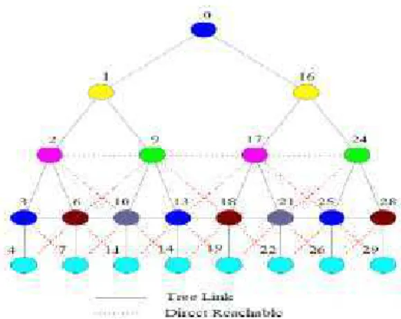
In a multi-hop beacon enabled network [3], each node has to prevent its beacons and data packets from destroying the beacons from its parent and its neighbor’s parent .i.e. to assign a contention-free time-slot to a node u in a tree type network—
• u’s time-slot must be different from u’s parent’s time-slot.
• u’s time-slot must not be the time-slot of the parent of anyone of u’s neighbors’, excluding u’s own children.
II. PROPOSAL OF GTS AND SDS IN CHAIN TOPOLOGY
Chain topology is a special case of cluster tree network. All the nodes are connected in a chain fashion. In the Fig.5 ten nodes are shown connected in chain topology. PNC is marked as P and shown in red color. All the nodes except the last node marked as A are FFD. Node marked as A is RFD. Data transmission is from node A to PNC through GTS using superframe scheduling approach.
Figure 5 Chain topology showing data transfer from A to P
(1)
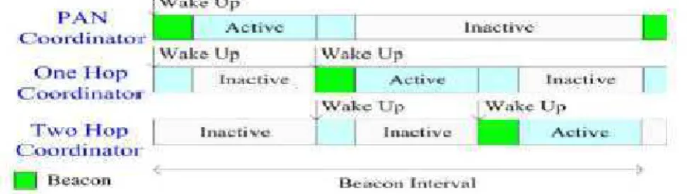
Scheduling of the superframe for PNC and its two hop neighbors is shown in Fig.7. Scheduling of the beacon frames is same to the scheduling shown in Fig.6. Green colored beacon frame of --- PNC (P) lies in 1st time slot, One Hop Coordinator (I) lies in 2nd time slot and so on.
Figure 7 Superframe duration scheduling
III. EVALUATION AND RESULTS
A node that has been [4] allocated a VGTS can transmit a message if and only if the whole transaction, including data transmission, the Intra-Frame Spacing (IFS), can be completed before the end of the GTS. Otherwise, it must wait until the next GTS. Parameters defined in our proposal are given in Table1.
For our proposed scheme we took 5Kbps data rate and 10 Micaz nodes. SoC used for our proposal analysis is XbeePro with development kit CC2520, Iwise-msp430f2618 and TELOSB-msp430f1611.
Equations from network calculus are used for analytical results and throughput is calculated at each and every node. Throughputs at some of the nodes are given in Table2
Figure 8 Throughput curve
Fig.8 shows the curve obtained for throughput through our proposed scheme for chain topology.
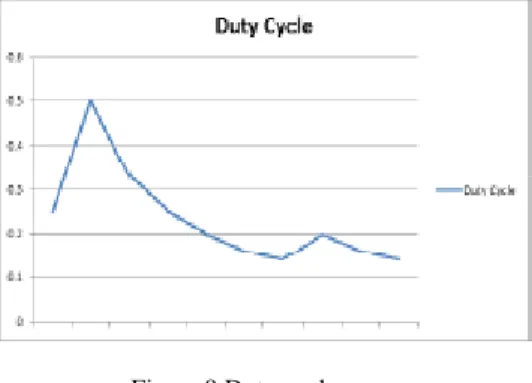
Figure 9 Duty cycle curve
Duty Cycle curve shows the variations but comparatively duty cycle is very low.
Figure 10 Efficiency Bar
Efficiency remains constant in our proposed scheme for chain topology network as shown in Fig.10.
IV. CONCLUSION
The scheme proposed in this approach provides a convenient way to use GTS in multihop. It also removes the limitations of GTS but shows that a very low throughput is achieved when GTS is used in large chain network.
With this approach a very low duty cycle and throughput is achieved.
ACKNOWLEDGEMENTS
Networks (LR-WPANs), 2006.
[2] A. Koubâa, A. Cunha, M. Alves, E. Tovar,”TDBS: a time division beacon scheduling mechanism for Zigbee cluster-tree wireless sensor networks”, Real-Time Systems, 40, 3(Dec.2008), pp. 321-354.
[3] Myung Lee, Jian Liang Zheng, Yong Liu,” Combined Beacon Scheduling Proposal to IEEE 802.15.4b” in the IEEE 802.15.4 TG 4b, September 2004.