A R C H I V E S
o f
F O U N D R Y E N G I N E E R I N G
Published quarterly as the organ of the Foundry Commission of the Polish Academy of Sciences
ISSN (1897-3310) Volume 10 Issue 2/2010
39 – 42
7/2
A R C H I V E S o f F O U N D R Y E N G I N E E R I N G V o l u m e 1 0 , I s s u e 2 / 2 0 1 0 , 3 9 - 4 2 39
The comparison of the structure
and microhardness of the tool steel C90
and HS 6-5-2 remelted with the electric arc
A. Dziedzic, S. Adamiak*
Institute of Technics, Rzeszow University, Rejtana 16 B, 35-310 Rzeszow, Poland *Corresponding author. E-mail address: [email protected]
Received 08.04.2010; accepted in revised form 10.05.2010
Abstract
The examination of the structure and microhardness of surface layer of C90 non-alloy steel and HS 6-5-2 high speed steel after electric arc treatment are presented in the paper. The comparison has been presented due to the similar content of the carbon in both steels. The structure of the remelted zone of the steel C90 before the conventional tempering consists of the cells, dendritic cells surrounded with the cementite, there is a plate martensite and retained austenite inside them, whereas the structure of the steel HS 6-5-2 is consistuted with cells, dendritic cells and dendrites surrounded with the eutectic system, inside of which there is a plate martensite and retained austenite. Such structure is characterized by the similar microhardness (790-800 HV0,065) and intensity of the tribiological wear. The tempering causes the decrease of the microhardness in non-alloy steel and the increase of the microhardness in high speed steel.
Keywords: Heat Treatment, Metallography, Microhardness, Tool Steel, Remelting of the Surface Layer, Electric Arc, Conventional
Tem-pering
1. Introduction
The tool steels consistute a very important group of materials used for the production, not only tools, but also machine ele-ments, that need to have the increased strength, for example the high-speed steels are used on the rolling bearing operating in high temperatures [1]. Modern technologies such as: laser treatment, electron treatment, CVD, PVD methods, give the possibility of forming the structure of the surface layer of steels providing the demaded properties. The economic factors direct research in using the plasma of the electric arc for shaping the surface layer of the machine elements and tools. Advantages of that method are the possibilities of receiving wider treated areas with one stream of the heat in comparison with the laser technologies or electron
ones. The structure can be shaped by the technological parameters regulations of the remelting process such as the amperage, speed
of the heat source or plasma formative gas composition [1÷5].
The aim of the paper was to compare microstructures and mi-crohardness of the non-alloy tool steel C90 and high-speed steel HS-6-5-2 remelted with the electric arc. The criteria of choosing those steels was similar to the content of carbon in tested steels.
2. Material and test methodology
A R C H I V E S o f F O U N D R Y E N G I N E E R I N G V o l u m e 1 0 , I s s u e 2 / 2 0 1 0 , 3 9 - 4 2 40
annealing. The samples for the tests were made in a shape of the cubicoid of the size 200x50x20 mm (Fig. 1).
Fig. 1. Shape of samples for the tests
The samples were remelted on the surface with the electric arc with the use of the FALTIG 315AC/DC apparatus. The single remelting was applied. The treatment parameters were used: amperage of the electric arc I = 100 A, speed of the electrode movement v=200 mm/min. As the plasma formative gas, the argon was used. The treatment has been conducted at the depart-ment of Foundry and Welding of Rzeszow University of Tech-nology. After the remelting, there has been the conventional
tempering done 1x1 hour in a temperature of 200°C for the steel
C90 and 2x2 hours in the temperature of 560°C for the steel HS
6-5-2. Parameters of tempering (temperature, time and multiplicity) of the tested steels were selected according to the standard PN-EN ISO 4957:2002U. The microhardeness measurements were made with the Hanemanna objective mph 100. The load used was 0,064 N, the operating time of the load was 10 s. Metallographic tests were conducted on the optical microscope - Neophot 2 and Tesla BS-340 electronic scanning microscope.
3. Results
Machine and tools elements made of the steel C90 and HS 6-5-2 immediately after the conventional hardening, need the tempering process. During the tempering, there is a transforma-tion of retained austenite into martensite and carbides release in martensite, what leads to the increase hardness of the high-speed steel, whereas in non-alloy steels tempering cause decrease the hardness.
The termodynamic conditions present in the remelting zone, shape its structure. Depending on the growth rate and temperature gradient, the cells, dendritic cells or dendrites can rise. Dendrites
rise with the negative temperature gradient – the heat generated at
the front of the crystalization is received through the liquid sur-rounding the rising crystal [6].
In spite of the similar content of carbon in tested steels, the significant difference in the content of alloy elements causes the occurance of the eutectic system in the steel structure HS 6-5-2 (mixture of product of the austenite transformation, and carbides
mainly M6C).
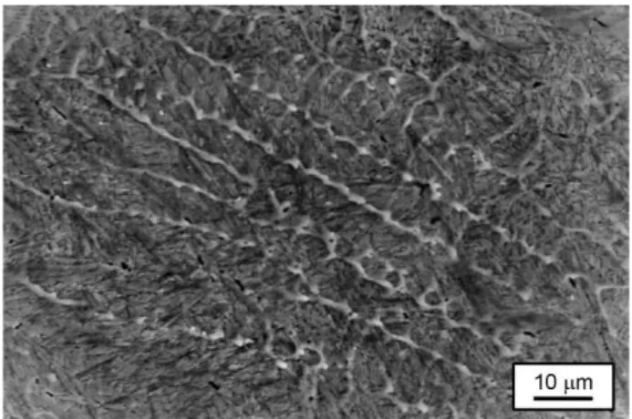
As a result of the remelting of the surface layer of the tested steels with the electric arc, the remelting zone and heat influence zone was obtained. The remelting zone structure of the tested
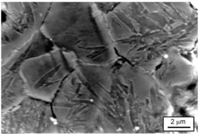
steels consituted the cells and dendritic cells (Fig. 2, 3), inside of which there was a plate martensite and retained austenite (Fig. 4, 5). In high speed steel HS 6-5-2 with the remelting zone, there were also dendrites observed (Fig. 6).
Fig. 2. Dendritic cells in the remelting zone of the C90 steel
Fig. 3. Cells in the remelting zone of the HS 6-5-2 steel
A R C H I V E S o f F O U N D R Y E N G I N E E R I N G V o l u m e 1 0 , I s s u e 2 / 2 0 1 0 , 3 9 - 4 2 41
On the cells borders in C90 steel there was the cementite (Fig. 2), which was released during the cooling from austenite, as a result of the decreasing with temperature the carbon solubility. In the high-speed steel HS 6-5-2, the space between the cells was filled eutectic (Fig. 7).
Fig. 5. Plate martensite and retained austenite inside the crystals in the remelting zone of the HS 6-5-2 steel
Fig. 6. Fragment of the dendrite in the remelting zone of the high speed HS 6-5-2 steel
Fig. 7. Eutectic grains on the borders of crystals of the high-speed HS 6-5-2 steel
In the heat influence zone of the tested steels, there was a process of dissolution of the carbides in the solid solution (Fig. 8). The structure of that zone consists with martensite, retained austenite. Near the core material, where the speed of cooling was lower, the bainite was observed (Fig. 9).
Fig. 8. Process of dissolution of the carbides in the solid solution
Fig. 9. Plate martensite, retained austenite and bainite in the heat influence zone of the C90 steel
In the remelting zone of the steel HS 6-5-2 during heating to the
temperature of tempering (560°C), there is a process release of
carbide ε, release of cementite and then solution of cementite and
release of carbides and during cooling from temperature of tem-pering, there is a transformation of retained austenite into marten-site. In the remelting zone of the steel C90 during heating to the
temperature of tempering (200°C), there is only a process release
of carbide ε. In that steel the transformation of the retained
auste-nite into martensite is present during the heating in temperature of
250-300°C.
A R C H I V E S o f F O U N D R Y E N G I N E E R I N G V o l u m e 1 0 , I s s u e 2 / 2 0 1 0 , 3 9 - 4 2 42
from the temperature of 1220°C in oil is 64 HRC, and steel C90
after the conventional hardening from 780°C in water - 64 HRC.
The alloy elements in the high speed steel will contribute to keep-ing the high hardness and tribological resistance in higher temper-atures of work.
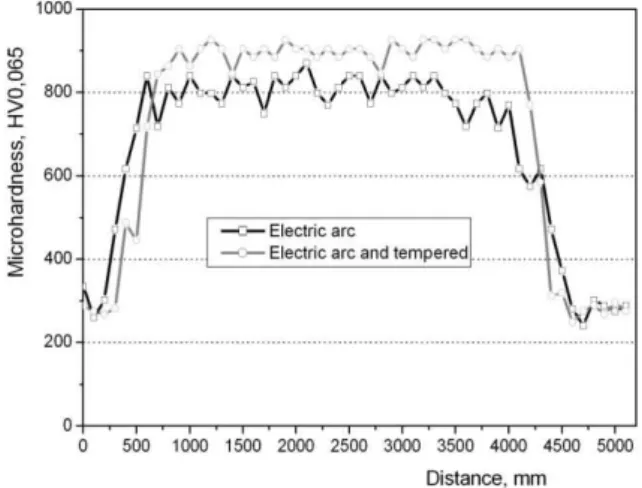
Fig. 10. Microhardness changes of the HS 6-5-2 steel remelted with the electric arc before and after tempering; measured on the track perpendicular to the direction of remelting 0,1 mm under the
sample surface
Fig. 11. Microhardness changes of the C90 steel remelted with the electric arc before and after tempering; measured on the track perpendicular to the direction of remelting from the surface to the
core
After conventional tempering, there is the increase of high-speed steel microhardeness to the value of 900 HV0,065 (Fig. 10).
In the cold work tool steel - C90 microhardness decreased up to 700HV0,065 (Fig. 11), which is caused by the release of carbide
ε.
The structure rising as a result of remelting with the electric arc of the surface layer of the steel C90 and HS 6-5-2 has also the
similar intensity of tribilogical wear (about 0,45 g/m3) in dry
friction conditions [7].
4. Conclusions
The structure of the remelting zone of the steel C90 steel be-fore conventional tempering consitute cells, dendritic cells, sur-rounded with the cementite, inside of which there is a plate mar-tensite and retained austenite, whereas the structure HS 6-5-2 steel consititute cells, dendritic cells and dendrites surrounded with the eutectic, inside of which there is a plate martensite and retained austenite. Such a structure is characterized with the similar micro-hardness (790-800 HV0,065) and intensity of the tribilogical wear.
Conducting conventional tempering of the steel HS6-5-2 creates the transformation of the retained austenite in martensite and release of carbides in martensite, what leads to the increase of the microhardeness in that steel, whereas in C90 steel there is
a release of carbide ε done, what leads to the decrease of the
microhardeness of that steel.
Literature
[1] L. Dobrzański, E. Hajduczek, L. Nowosielski: Physical
metallurgy and heat treatment of tools materials, WNT,
Warsaw, 1990 (in Polish)
[2] A.W. Orłowicz, A.Trytek: Effect of rapid solidification on
sliding wear of iron castings, Wear 9258, 2002
[3] Z. Nitkiewicz, J. Iwaszko: The use of arc plasma in surface
engineering. Material engineering, 6, 373-375, 2000, (in Polish)
[4] A.W.Orłowicz, M.Mróz: Thermal coefficients of the
GTAW method. Archives of Foundry, Year 2003, no 3, 2003, (in Polish)
[5] Y.Adonyj, R.W.Richardson, W.A.Beaslack: Investigation of
arc force effects in surface GTAW welding. Welding Jour-nal, 9, 35-44, 1996
[6] E. Fraś: Crystallization of metals, WNT Warszawa 2003
[7] S. Adamiak, A. Dziedzic: Comparing the tribiological